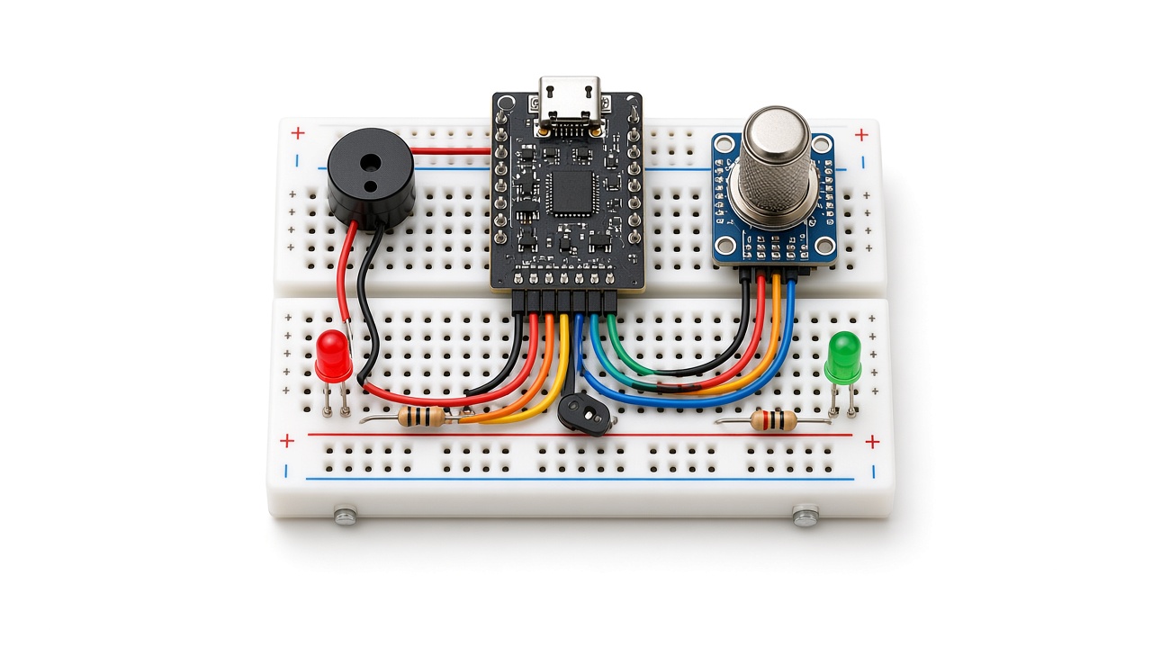
ESP32 Air Quality Monitor with PMS5003, BME280, MQ-135, OLED & Web Dashboard

ESP32 air quality monitor with PMS5003, BME280, MQ-135, SSD1306 OLED, RGB LED and buzzer

Build an ESP32 air quality monitor with a PMS5003 dust sensor, BME280, MQ-135, OLED, RGB AQI LED, buzzer and a live Wi-Fi dashboard. Wiring table, diagram and full code.

  • DifficultyAdvanced
  • Build time5–8 hours
  • Board / MCUESP32 DevKit
  • Parts11 items
  • CodeArduino C++

Need it ready-made? Buy Ready Project

This ESP32 air quality monitor measures the fine dust you breathe (PM1.0, PM2.5 and PM10) with a Plantower PMS5003 laser sensor, adds temperature, humidity and pressure from a BME280, and a general gas level from an MQ-135. It works out an AQI value for PM2.5 using the Indian National AQI bands, shows everything on a 0.96 inch OLED, lights an RGB LED from green to red, beeps when the air turns poor, and serves a live dashboard you can open on any phone on your Wi-Fi.

It is a big, multi-sensor IoT build that combines UART, I2C, ADC and PWM on one board. It is useful for bedrooms, classrooms, workshops, and for checking how well an air purifier works during winter smog.

ESP32 air quality monitor with PMS5003, BME280, MQ-135, SSD1306 OLED, RGB LED and buzzer

How It Works

  • PMS5003 dust sensor: a small fan pulls air through a laser beam. Light scattered by particles is counted and the sensor sends a 32-byte frame every second over serial at 9600 baud. The ESP32 reads it on UART2 (GPIO16/17), checks the checksum and takes the atmospheric PM1.0, PM2.5 and PM10 values in µg/m³.
  • AQI calculation: the PM2.5 value is converted with the Indian NAQI breakpoints (0-30 Good, 31-60 Satisfactory, 61-90 Moderate, 91-120 Poor, 121-250 Very Poor, above 250 Severe). The official AQI uses 24-hour averages, so the live number is a guide, not a certified reading.
  • BME280: reports temperature, relative humidity and air pressure over I2C on the same bus as the OLED (GPIO21 SDA, GPIO22 SCL).
  • MQ-135: its heater runs on 5V and the analog output rises when gases such as smoke, alcohol or ammonia are present. A 10k/20k divider keeps the signal below 3.3V for GPIO34. The value is shown as a raw relative level, because the MQ-135 is not accurate enough for real ppm readings without calibration.
  • Status outputs: the RGB LED shows the AQI colour (purple means no data from the PMS5003 for 10 seconds). Above AQI 200 the buzzer gives a short beep once a minute through a BC547 transistor.
  • Web dashboard: the ESP32 joins your Wi-Fi and serves a page at its IP address. The page fetches /data as JSON every 3 seconds, so the cards update without reloading.

Components Required

  • ESP32 DevKit V1 (30-pin) – 1
  • Plantower PMS5003 particulate sensor with its 8-pin cable (or an adapter board) – 1
  • BME280 temperature, humidity and pressure module (I2C) – 1
  • MQ-135 air quality sensor module – 1
  • 0.96 inch SSD1306 I2C OLED, 128×64 – 1
  • Common-cathode RGB LED (5 mm) – 1
  • Active 5V buzzer – 1
  • BC547 NPN transistor – 1
  • Resistors: 220 Ω – 3, 1k – 1, 10k – 1, 20k – 1
  • 5V 2A USB adapter and cable – 1
  • Breadboard or perfboard and jumper wires

Wiring Table

Module pinESP32 pinNotes
PMS5003 pin 1 (VCC)VIN (5V)The fan needs 5V; logic is 3.3V so it connects directly
PMS5003 pin 2 (GND)GND
PMS5003 pin 3 (SET)GPIO4HIGH keeps the sensor running
PMS5003 pin 4 (RX)GPIO17 (TX2)
PMS5003 pin 5 (TX)GPIO16 (RX2)
PMS5003 pins 6, 7, 8Not connectedRESET has an internal pull-up
BME280 VIN / GND3V3 / GND
BME280 SDA / SCLGPIO21 / GPIO22I2C address 0x76 (0x77 also tried)
OLED VCC / GND3V3 / GND
OLED SDA / SCLGPIO21 / GPIO22Shared I2C bus, address 0x3C
MQ-135 VCC / GNDVIN (5V) / GNDLet it warm up for 24 hours the first time
MQ-135 AOGPIO34 via 10k20k from GPIO34 to GND (divider)
RGB LED red / green / blueGPIO25 / GPIO26 / GPIO27220 Ω on each leg
RGB LED cathodeGNDLongest leg
BC547 baseGPIO33 via 1kEmitter to GND
Buzzer +5VBuzzer – to BC547 collector

Connection Diagram

The illustration above shows the general layout; its wire routes are only for orientation. The pin-accurate drawing below matches the wiring table exactly, so follow it while building.

ESP32 Air Quality Monitor – Pin-Accurate Wiring Power USB 5V: ESP32 VIN feeds PMS5003 pin 1 (VCC 5V) and MQ-135 VCC ESP32 GND: common ground for every module PMS5003 Pin 2 GND to GND, pin 3 SET to GPIO4 Pin 4 RX to GPIO17 (TX2), pin 5 TX to GPIO16 (RX2) Pins 6 RESET and 7, 8 NC: leave unconnected BME280 VIN to 3V3, GND to GND SDA to GPIO21, SCL to GPIO22 (address 0x76) SSD1306 OLED VCC to 3V3, GND to GND SDA to GPIO21, SCL to GPIO22 (address 0x3C) MQ-135 VCC to 5V (VIN), GND to GND AO through 10k to GPIO34, 20k from GPIO34 to GND RGB LED Red to GPIO25, green to GPIO26, blue to GPIO27, each via 220 Ω Common cathode (longest leg) to GND Buzzer GPIO33 via 1k to BC547 base, emitter to GND Buzzer + to 5V, buzzer – to BC547 collector
Pin-accurate connection diagram for the ESP32 air quality monitor.

Code

Install the ESP32 board package in the Arduino IDE and choose ESP32 Dev Module. From the Library Manager install Adafruit BME280, Adafruit Unified Sensor, Adafruit SSD1306 and Adafruit GFX. The PMS5003 is read directly, so it needs no library. Replace the Wi-Fi placeholders with your own network name and password, upload, and open the Serial Monitor at 115200 baud to see the dashboard address.

/*
  ESP32 Air Quality Monitor
  PMS5003 (PM1.0 / PM2.5 / PM10) + BME280 (temperature, humidity, pressure)
  + MQ-135 (relative gas level) + SSD1306 OLED + RGB status LED + buzzer
  + Wi-Fi web dashboard with live JSON data.

  Board: ESP32 Dev Module (ESP32 DevKit V1)
  Libraries: Adafruit BME280, Adafruit Unified Sensor, Adafruit SSD1306, Adafruit GFX
  The PMS5003 is read directly over UART2 (no extra library needed).
*/

#include <WiFi.h>
#include <WebServer.h>
#include <Wire.h>
#include <Adafruit_GFX.h>
#include <Adafruit_SSD1306.h>
#include <Adafruit_BME280.h>

// ---------- User settings ----------
const char* WIFI_SSID     = "YOUR_WIFI_SSID";      // placeholder: put your Wi-Fi name
const char* WIFI_PASSWORD = "YOUR_WIFI_PASSWORD";  // placeholder: put your Wi-Fi password

// ---------- Pins ----------
#define PMS_RX_PIN   16   // ESP32 RX2  <- PMS5003 TX (pin 5)
#define PMS_TX_PIN   17   // ESP32 TX2  -> PMS5003 RX (pin 4)
#define PMS_SET_PIN  4    // HIGH = sensor running, LOW = sleep (fan off)
#define MQ135_PIN    34   // MQ-135 AO through a 10k/20k divider (ADC1, input only)
#define LED_R_PIN    25   // RGB LED red   (through 220 ohm)
#define LED_G_PIN    26   // RGB LED green (through 220 ohm)
#define LED_B_PIN    27   // RGB LED blue  (through 220 ohm)
#define BUZZER_PIN   33   // Active buzzer via BC547 transistor
// I2C: SDA = GPIO21, SCL = GPIO22 (BME280 at 0x76, OLED at 0x3C)

// ---------- Objects ----------
Adafruit_SSD1306 display(128, 64, &Wire, -1);
Adafruit_BME280 bme;
WebServer server(80);
HardwareSerial pmsSerial(2);

// ---------- Readings ----------
struct Readings {
  uint16_t pm1 = 0, pm25 = 0, pm10 = 0;
  float tempC = NAN, hum = NAN, pressHpa = NAN;
  int gasRaw = 0;          // 0-4095 relative gas level from MQ-135
  int aqi = 0;             // India NAQI sub-index for PM2.5
  bool pmsOk = false;
} r;

bool bmeOk = false;
unsigned long lastPmsFrame = 0;
unsigned long lastScreen = 0;
unsigned long lastBeep = 0;

// ---------- India NAQI sub-index for PM2.5 (24-h breakpoints, used here as live guide) ----------
int pm25ToAqi(float c) {
  // {C_low, C_high, I_low, I_high}
  const float bp[6][4] = {
    {0, 30, 0, 50}, {31, 60, 51, 100}, {61, 90, 101, 200},
    {91, 120, 201, 300}, {121, 250, 301, 400}, {251, 500, 401, 500}
  };
  if (c > 500) return 500;
  for (int i = 0; i < 6; i++) {
    if (c <= bp[i][1]) {
      if (c < bp[i][0]) c = bp[i][0];
      return (int)((bp[i][3] - bp[i][2]) / (bp[i][1] - bp[i][0]) * (c - bp[i][0]) + bp[i][2]);
    }
  }
  return 500;
}

const char* aqiLabel(int aqi) {
  if (aqi <= 50)  return "Good";
  if (aqi <= 100) return "Satisfactory";
  if (aqi <= 200) return "Moderate";
  if (aqi <= 300) return "Poor";
  if (aqi <= 400) return "Very Poor";
  return "Severe";
}

// ---------- RGB LED colour by AQI ----------
void setLed(uint8_t red, uint8_t green, uint8_t blue) {
  analogWrite(LED_R_PIN, red);
  analogWrite(LED_G_PIN, green);
  analogWrite(LED_B_PIN, blue);
}

void showAqiColour(int aqi) {
  if (aqi <= 50)       setLed(0, 255, 0);     // green
  else if (aqi <= 100) setLed(120, 255, 0);   // light green
  else if (aqi <= 200) setLed(255, 180, 0);   // yellow
  else if (aqi <= 300) setLed(255, 80, 0);    // orange
  else                 setLed(255, 0, 0);     // red
}

// ---------- PMS5003 frame reader ----------
// Frame: 0x42 0x4D, length(2), 13 data words, checksum(2) = 32 bytes total
bool readPms() {
  static uint8_t buf[32];
  static uint8_t idx = 0;
  bool gotFrame = false;

  while (pmsSerial.available()) {
    uint8_t b = pmsSerial.read();
    if (idx == 0 && b != 0x42) continue;          // wait for start byte 1
    if (idx == 1 && b != 0x4D) { idx = 0; continue; } // start byte 2
    buf[idx++] = b;
    if (idx == 32) {
      idx = 0;
      uint16_t sum = 0;
      for (int i = 0; i < 30; i++) sum += buf[i];
      uint16_t check = (buf[30] << 8) | buf[31];
      if (sum == check) {
        // Atmospheric-environment values (words 4-6) are the ones to show
        r.pm1  = (buf[10] << 8) | buf[11];
        r.pm25 = (buf[12] << 8) | buf[13];
        r.pm10 = (buf[14] << 8) | buf[15];
        r.pmsOk = true;
        gotFrame = true;
      }
    }
  }
  return gotFrame;
}

// ---------- Other sensors ----------
void readOtherSensors() {
  if (bmeOk) {
    r.tempC = bme.readTemperature();
    r.hum = bme.readHumidity();
    r.pressHpa = bme.readPressure() / 100.0F;
  }
  // Average 16 samples to smooth the MQ-135 output
  long total = 0;
  for (int i = 0; i < 16; i++) total += analogRead(MQ135_PIN);
  r.gasRaw = total / 16;
}

// ---------- OLED ----------
void drawScreen() {
  display.clearDisplay();
  display.setTextColor(SSD1306_WHITE);
  display.setTextSize(1);
  display.setCursor(0, 0);
  display.print("AQI ");
  display.print(r.aqi);
  display.print(" ");
  display.print(aqiLabel(r.aqi));

  display.setTextSize(2);
  display.setCursor(0, 12);
  display.print("PM2.5 ");
  display.print(r.pm25);

  display.setTextSize(1);
  display.setCursor(0, 32);
  display.printf("PM1 %u  PM10 %u", r.pm1, r.pm10);
  display.setCursor(0, 42);
  if (bmeOk) display.printf("%.1fC  %.0f%%  %.0fhPa", r.tempC, r.hum, r.pressHpa);
  else display.print("BME280 not found");
  display.setCursor(0, 54);
  display.printf("Gas %d  ", r.gasRaw);
  if (WiFi.status() == WL_CONNECTED) display.print(WiFi.localIP());
  else display.print("No Wi-Fi");
  display.display();
}

// ---------- Web dashboard ----------
const char PAGE[] PROGMEM = R"HTML(
<!DOCTYPE html><html><head><meta charset="utf-8">
<meta name="viewport" content="width=device-width,initial-scale=1">
<title>ESP32 Air Quality</title>
<style>
body{font-family:Arial,sans-serif;background:#f4f6f8;margin:0;padding:16px;text-align:center}
.grid{display:grid;grid-template-columns:repeat(auto-fit,minmax(140px,1fr));gap:12px;max-width:700px;margin:auto}
.card{background:#fff;border-radius:10px;padding:14px;box-shadow:0 1px 4px #0002}
.v{font-size:28px;font-weight:bold}.l{color:#666;font-size:13px}
#aqi{font-size:48px;font-weight:bold}
</style></head><body>
<h2>ESP32 Air Quality Monitor</h2>
<div class="card" style="max-width:700px;margin:0 auto 12px"><div id="aqi">--</div><div id="lab" class="l">loading</div></div>
<div class="grid">
<div class="card"><div class="v" id="pm25">--</div><div class="l">PM2.5 (ug/m3)</div></div>
<div class="card"><div class="v" id="pm10">--</div><div class="l">PM10 (ug/m3)</div></div>
<div class="card"><div class="v" id="pm1">--</div><div class="l">PM1.0 (ug/m3)</div></div>
<div class="card"><div class="v" id="t">--</div><div class="l">Temperature (C)</div></div>
<div class="card"><div class="v" id="h">--</div><div class="l">Humidity (%)</div></div>
<div class="card"><div class="v" id="p">--</div><div class="l">Pressure (hPa)</div></div>
<div class="card"><div class="v" id="g">--</div><div class="l">Gas level (MQ-135 raw)</div></div>
</div>
<script>
const col=a=>a<=50?'#2e7d32':a<=100?'#7cb342':a<=200?'#f9a825':a<=300?'#ef6c00':'#c62828';
async function up(){try{const d=await (await fetch('/data')).json();
for(const k of ['pm25','pm10','pm1','g'])document.getElementById(k).textContent=d[k];
document.getElementById('t').textContent=d.t;document.getElementById('h').textContent=d.h;
document.getElementById('p').textContent=d.p;
const a=document.getElementById('aqi');a.textContent=d.aqi;a.style.color=col(d.aqi);
document.getElementById('lab').textContent='AQI (PM2.5): '+d.label;}catch(e){}}
up();setInterval(up,3000);
</script></body></html>
)HTML";

void handleRoot() { server.send_P(200, "text/html", PAGE); }

void handleData() {
  char json[256];
  snprintf(json, sizeof(json),
    "{\"pm1\":%u,\"pm25\":%u,\"pm10\":%u,\"t\":\"%.1f\",\"h\":\"%.0f\",\"p\":\"%.0f\",\"g\":%d,\"aqi\":%d,\"label\":\"%s\"}",
    r.pm1, r.pm25, r.pm10, r.tempC, r.hum, r.pressHpa, r.gasRaw, r.aqi, aqiLabel(r.aqi));
  server.send(200, "application/json", json);
}

// ---------- Setup ----------
void setup() {
  Serial.begin(115200);

  pinMode(PMS_SET_PIN, OUTPUT);
  digitalWrite(PMS_SET_PIN, HIGH);        // keep the PMS5003 awake
  pinMode(BUZZER_PIN, OUTPUT);
  digitalWrite(BUZZER_PIN, LOW);
  pinMode(LED_R_PIN, OUTPUT);
  pinMode(LED_G_PIN, OUTPUT);
  pinMode(LED_B_PIN, OUTPUT);
  setLed(0, 0, 255);                      // blue while starting
  analogReadResolution(12);

  pmsSerial.begin(9600, SERIAL_8N1, PMS_RX_PIN, PMS_TX_PIN);
  Wire.begin(21, 22);

  if (!display.begin(SSD1306_SWITCHCAPVCC, 0x3C)) Serial.println("OLED not found");
  display.clearDisplay();
  display.setTextColor(SSD1306_WHITE);
  display.setCursor(0, 0);
  display.println("Air Quality Monitor");
  display.println("Warming up sensors...");
  display.display();

  bmeOk = bme.begin(0x76) || bme.begin(0x77);
  if (!bmeOk) Serial.println("BME280 not found, check wiring");

  WiFi.mode(WIFI_STA);
  WiFi.begin(WIFI_SSID, WIFI_PASSWORD);
  unsigned long start = millis();
  while (WiFi.status() != WL_CONNECTED && millis() - start < 15000) delay(250);
  if (WiFi.status() == WL_CONNECTED) {
    Serial.print("Dashboard: http://");
    Serial.println(WiFi.localIP());
  } else {
    Serial.println("Wi-Fi not connected, running offline");
  }

  server.on("/", handleRoot);
  server.on("/data", handleData);
  server.begin();
}

// ---------- Loop ----------
void loop() {
  server.handleClient();

  if (readPms()) {
    lastPmsFrame = millis();
    r.aqi = pm25ToAqi(r.pm25);
    showAqiColour(r.aqi);
  }
  // No valid frame for 10 s: show purple to flag a PMS5003 problem
  if (millis() - lastPmsFrame > 10000) {
    r.pmsOk = false;
    setLed(150, 0, 255);
  }

  if (millis() - lastScreen > 2000) {
    lastScreen = millis();
    readOtherSensors();
    drawScreen();
  }

  // Short beep every 60 s while AQI is Poor (above 200)
  if (r.pmsOk && r.aqi > 200 && millis() - lastBeep > 60000) {
    lastBeep = millis();
    digitalWrite(BUZZER_PIN, HIGH);
    delay(300);
    digitalWrite(BUZZER_PIN, LOW);
  }
}

Troubleshooting

ProblemFix
LED stays purple and PM values are 0TX and RX are probably swapped. PMS5003 TX (pin 5) must go to GPIO16. Also check that SET is HIGH and the fan is spinning.
BME280 not foundCheck SDA/SCL and the address. Some purple boards are BMP280 (no humidity), which this code does not support.
OLED is blankCheck the address 0x3C and that VCC is on 3V3. Run an I2C scanner if unsure.
MQ-135 value keeps fallingNormal for a new sensor. Leave it powered for a day to burn in, then note the clean-air value as your baseline.
PM readings jump in humid weatherAbove about 85% humidity water droplets are counted as dust. Compare with the BME280 humidity before trusting a high reading.

Ideas to Extend

  • Log readings to Google Sheets or ThingSpeak every 5 minutes for daily graphs.
  • Put the PMS5003 to sleep (SET LOW) between readings to extend the fan life.
  • Switch an air purifier through a relay when AQI goes above 150.
  • Add an SCD40 sensor for true CO2 readings in closed rooms.
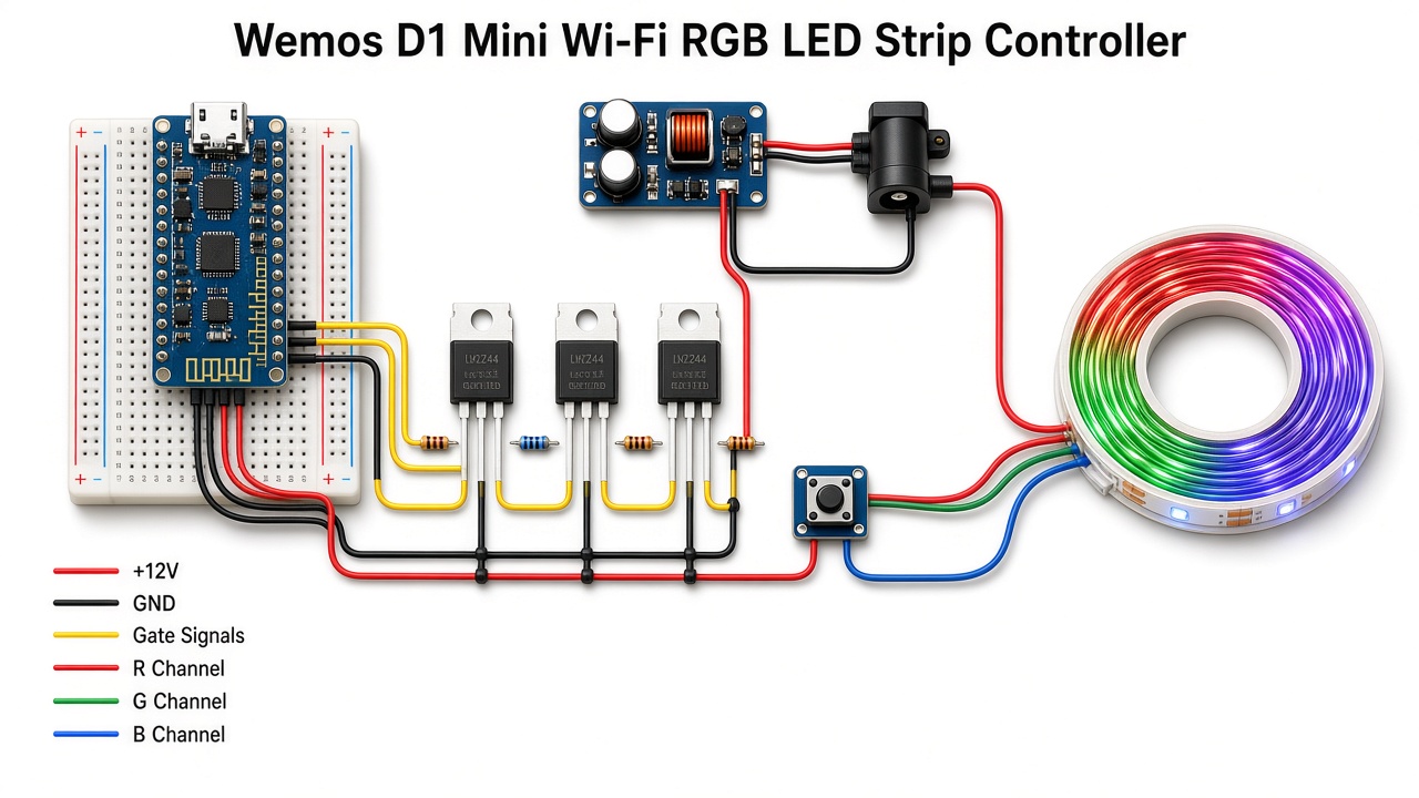
Wemos D1 Mini Wi-Fi RGB LED Strip Controller with Web Colour Picker

Wemos D1 Mini Wi-Fi RGB LED strip controller with three IRLZ44N MOSFETs, buck converter, push button and 12V RGB strip

Build a Wemos D1 Mini Wi-Fi RGB LED strip controller with IRLZ44N MOSFETs, a web colour picker, brightness slider, rainbow mode and a push button. Wiring table, diagram and full code.

  • DifficultyIntermediate
  • Build time2–4 hours
  • Board / MCUWemos D1 Mini (ESP8266)
  • Parts10 items
  • CodeArduino C++

Need it ready-made? Buy Ready Project

This Wemos D1 Mini RGB LED strip controller lets you set any colour and brightness on an ordinary 12V RGB (5050) LED strip from your phone’s browser. No app is needed: the ESP8266 hosts a small web page with a colour picker, a brightness slider, ON/OFF buttons and a smooth rainbow mode. A push button on the board switches the strip on and off without a phone, and the last setting is remembered after a power cut.

It is a practical medium-level IoT project for room backlighting, a TV bias light, a desk or a shop display, and a good way to learn PWM dimming with logic-level MOSFETs.

Wemos D1 Mini Wi-Fi RGB LED strip controller with three IRLZ44N MOSFETs, buck converter, push button and 12V RGB strip

How It Works

  • The strip: a common-anode 12V RGB strip has four wires: +12V and one return wire each for red, green and blue. A colour lights up when its return wire is pulled to ground.
  • MOSFET switches: three IRLZ44N logic-level MOSFETs act as low-side switches. Each gate is driven straight from a 3.3V D1 Mini pin through a 100 Ω resistor, and a 10k pull-down keeps the strip off while the board boots.
  • PWM dimming: the ESP8266 drives D5, D6 and D7 with 1 kHz, 10-bit PWM. The code applies a simple gamma curve so low brightness levels look smooth to the eye.
  • Web control: the board joins your Wi-Fi and serves a page at its IP address. Moving the colour picker or slider sends a short request such as /set?hex=ff7828 and the colour changes instantly.
  • Rainbow mode: the code steps through all 360 hues every 30 ms for a slow, continuous colour fade.
  • Memory and button: colour, brightness, power and mode are stored in EEPROM 3 seconds after the last change, so a slider drag does not wear the flash. The D2 button toggles the strip with a 50 ms debounce.
  • Power: one 12V adapter feeds the strip directly and an LM2596 buck converter makes 5V for the D1 Mini.

Components Required

  • Wemos D1 Mini (ESP8266) – 1
  • 12V RGB 5050 LED strip, common anode, up to 5 m – 1
  • IRLZ44N logic-level N-channel MOSFET – 3
  • Resistors: 100 Ω – 3, 10k – 3
  • LM2596 buck converter module (set to 5V) – 1
  • 12V DC adapter, 2A for 2 m or 5A for 5 m of strip – 1
  • DC barrel jack – 1
  • Tactile push button – 1
  • 470 µF 25V electrolytic capacitor – 1
  • Breadboard or perfboard, screw terminals and jumper wires

Wiring Table

FromToNotes
12V adapter (+)Strip +12V wire and LM2596 IN+
12V adapter (-)LM2596 IN-, MOSFET sources, D1 Mini GOne common ground
LM2596 OUT+D1 Mini 5VAdjust to 5.0V before connecting
LM2596 OUT-D1 Mini G
D1 Mini D5 (GPIO14)IRLZ44N #1 gate via 100 Ω10k from gate to GND
IRLZ44N #1 drainStrip R wireSource to GND
D1 Mini D6 (GPIO12)IRLZ44N #2 gate via 100 Ω10k from gate to GND
IRLZ44N #2 drainStrip G wireSource to GND
D1 Mini D7 (GPIO13)IRLZ44N #3 gate via 100 Ω10k from gate to GND
IRLZ44N #3 drainStrip B wireSource to GND
Push buttonD2 (GPIO4) and GNDUses the internal pull-up
470 µF capacitor+12V and GND at the stripObserve polarity

IRLZ44N pins, with the printed face toward you and legs down: gate, drain, source (left to right).

Connection Diagram

The illustration above shows a typical layout; its wire routes are only for orientation. The pin-accurate drawing below matches the wiring table exactly, so follow it while building.

Wemos D1 Mini RGB Strip Controller – Pin-Accurate Wiring 12V supply 12V DC adapter (+): strip +12V wire and LM2596 IN+ 12V DC adapter (-): common GND, LM2596 IN-, all MOSFET sources Buck converter LM2596 set to 5.0V before connecting the board OUT+ to Wemos 5V pin, OUT- to Wemos G (GND) Red channel D5 (GPIO14) via 100 Ω to IRLZ44N #1 gate, 10k gate to GND MOSFET #1 drain to strip R, source to GND Green channel D6 (GPIO12) via 100 Ω to IRLZ44N #2 gate, 10k gate to GND MOSFET #2 drain to strip G, source to GND Blue channel D7 (GPIO13) via 100 Ω to IRLZ44N #3 gate, 10k gate to GND MOSFET #3 drain to strip B, source to GND Button Push button between D2 (GPIO4) and GND (internal pull-up) Bulk capacitor 470 µF 25V across 12V and GND near the strip connector
Pin-accurate connection diagram for the Wemos D1 Mini RGB LED strip controller.

Code

Install the ESP8266 board package in the Arduino IDE (Boards Manager, search “esp8266”), choose LOLIN(WEMOS) D1 R2 & mini, put your Wi-Fi name and password in place of the placeholders, and upload. No extra libraries are needed. Open the Serial Monitor at 115200 baud to see the board’s IP address, then open that address in your phone’s browser.

/*
  Wemos D1 Mini Wi-Fi RGB LED Strip Controller
  - 12V common-anode RGB (5050) strip driven by 3x IRLZ44N logic-level MOSFETs
  - Web page with colour picker, brightness slider, ON/OFF and Rainbow mode
  - Push button on D2 toggles the strip ON/OFF without a phone
  - Last colour, brightness and mode are saved in EEPROM
  Board: LOLIN(WEMOS) D1 R2 & mini (ESP8266 core). No extra libraries needed.
*/
#include <ESP8266WiFi.h>
#include <ESP8266WebServer.h>
#include <EEPROM.h>

const char* WIFI_SSID = "YOUR_WIFI_SSID";       // <-- your Wi-Fi name
const char* WIFI_PASS = "YOUR_WIFI_PASSWORD";   // <-- your Wi-Fi password

// MOSFET gate pins (each through a 100 ohm resistor, 10k pull-down to GND)
const uint8_t PIN_R = D5;   // GPIO14
const uint8_t PIN_G = D6;   // GPIO12
const uint8_t PIN_B = D7;   // GPIO13
const uint8_t PIN_BTN = D2; // GPIO4, push button to GND

ESP8266WebServer server(80);

// Current settings
uint8_t red = 255, green = 120, blue = 40;  // warm white default
uint8_t brightness = 80;                    // 0-100 %
bool powerOn = true;
bool rainbow = false;

uint16_t hue = 0;                 // used by rainbow mode (0-359)
unsigned long lastStep = 0;
unsigned long lastSaveRequest = 0;
bool savePending = false;

// ---------- EEPROM storage ----------
const uint8_t MAGIC = 0x37;
void saveSettings() {
  EEPROM.write(0, MAGIC);
  EEPROM.write(1, red);
  EEPROM.write(2, green);
  EEPROM.write(3, blue);
  EEPROM.write(4, brightness);
  EEPROM.write(5, powerOn);
  EEPROM.write(6, rainbow);
  EEPROM.commit();
}
void loadSettings() {
  if (EEPROM.read(0) != MAGIC) return;   // first boot: keep defaults
  red = EEPROM.read(1);
  green = EEPROM.read(2);
  blue = EEPROM.read(3);
  brightness = constrain(EEPROM.read(4), 0, 100);
  powerOn = EEPROM.read(5);
  rainbow = EEPROM.read(6);
}
// Delay EEPROM writes so dragging a slider doesn't wear the flash
void requestSave() { savePending = true; lastSaveRequest = millis(); }

// ---------- Output ----------
// Simple gamma correction so low brightness looks smooth
uint16_t gamma10(uint8_t v) {
  float f = v / 255.0;
  return (uint16_t)(f * f * 1023.0 + 0.5);
}
void writeRGB(uint8_t r, uint8_t g, uint8_t b) {
  if (!powerOn) { r = g = b = 0; }
  uint16_t scale = brightness;   // 0-100
  analogWrite(PIN_R, gamma10(r) * scale / 100);
  analogWrite(PIN_G, gamma10(g) * scale / 100);
  analogWrite(PIN_B, gamma10(b) * scale / 100);
}
// Convert hue (0-359) at full saturation to RGB
void hueToRGB(uint16_t h, uint8_t &r, uint8_t &g, uint8_t &b) {
  uint8_t region = h / 60;
  uint8_t rem = (h % 60) * 255 / 60;
  switch (region) {
    case 0: r = 255; g = rem; b = 0; break;
    case 1: r = 255 - rem; g = 255; b = 0; break;
    case 2: r = 0; g = 255; b = rem; break;
    case 3: r = 0; g = 255 - rem; b = 255; break;
    case 4: r = rem; g = 0; b = 255; break;
    default: r = 255; g = 0; b = 255 - rem; break;
  }
}
void applyOutput() {
  if (rainbow) return;   // rainbow updates itself in loop()
  writeRGB(red, green, blue);
}

// ---------- Web page ----------
const char PAGE[] PROGMEM = R"HTML(
<!DOCTYPE html><html><head><meta name="viewport" content="width=device-width,initial-scale=1">
<title>RGB Strip</title>
<style>body{font-family:Arial;text-align:center;background:#111;color:#eee;margin:0;padding:20px}
input[type=color]{width:160px;height:160px;border:none;background:none}
input[type=range]{width:80%}button{font-size:18px;margin:8px;padding:12px 22px;border:0;border-radius:8px}
#on{background:#2e7d32;color:#fff}#off{background:#c62828;color:#fff}#rb{background:#6a1b9a;color:#fff}</style></head>
<body><h2>Wi-Fi RGB Strip</h2>
<input type="color" id="c" value="#ff7828"><br>
<p>Brightness: <span id="bv">80</span>%</p><input type="range" id="br" min="0" max="100" value="80"><br>
<button id="on">ON</button><button id="off">OFF</button><button id="rb">Rainbow</button>
<p id="st"></p>
<script>
function send(q){fetch('/set?'+q).then(r=>r.json()).then(show);}
function show(s){document.getElementById('st').innerText=(s.power?'ON':'OFF')+(s.rainbow?' - Rainbow':'');
 document.getElementById('br').value=s.bright;document.getElementById('bv').innerText=s.bright;
 if(!s.rainbow)document.getElementById('c').value=s.hex;}
c.oninput=e=>send('hex='+e.target.value.substring(1));
br.oninput=e=>{bv.innerText=e.target.value;send('bright='+e.target.value);};
on.onclick=()=>send('power=1');off.onclick=()=>send('power=0');rb.onclick=()=>send('rainbow=1');
fetch('/state').then(r=>r.json()).then(show);
</script></body></html>
)HTML";

String stateJSON() {
  char hex[8];
  snprintf(hex, sizeof(hex), "#%02x%02x%02x", red, green, blue);
  String s = "{\"power\":"; s += powerOn ? 1 : 0;
  s += ",\"rainbow\":"; s += rainbow ? 1 : 0;
  s += ",\"bright\":"; s += brightness;
  s += ",\"hex\":\""; s += hex; s += "\"}";
  return s;
}

void handleRoot() { server.send_P(200, "text/html", PAGE); }
void handleState() { server.send(200, "application/json", stateJSON()); }
void handleSet() {
  if (server.hasArg("hex")) {               // e.g. hex=ff7828
    long v = strtol(server.arg("hex").c_str(), NULL, 16);
    red = (v >> 16) & 0xFF; green = (v >> 8) & 0xFF; blue = v & 0xFF;
    rainbow = false; powerOn = true;
  }
  if (server.hasArg("bright")) brightness = constrain(server.arg("bright").toInt(), 0, 100);
  if (server.hasArg("power")) powerOn = server.arg("power").toInt() == 1;
  if (server.hasArg("rainbow")) { rainbow = server.arg("rainbow").toInt() == 1; powerOn = true; }
  applyOutput();
  requestSave();
  server.send(200, "application/json", stateJSON());
}

// ---------- Button ----------
bool lastBtn = HIGH;
unsigned long lastBtnChange = 0;
void checkButton() {
  bool b = digitalRead(PIN_BTN);
  if (b != lastBtn && millis() - lastBtnChange > 50) {   // 50 ms debounce
    lastBtnChange = millis();
    lastBtn = b;
    if (b == LOW) {            // pressed
      powerOn = !powerOn;
      applyOutput();
      if (!powerOn) writeRGB(0, 0, 0);
      requestSave();
    }
  }
}

void setup() {
  Serial.begin(115200);
  pinMode(PIN_R, OUTPUT); pinMode(PIN_G, OUTPUT); pinMode(PIN_B, OUTPUT);
  pinMode(PIN_BTN, INPUT_PULLUP);
  analogWriteRange(1023);     // 10-bit PWM
  analogWriteFreq(1000);      // 1 kHz, flicker-free for LED strips
  EEPROM.begin(16);
  loadSettings();
  applyOutput();

  WiFi.mode(WIFI_STA);
  WiFi.hostname("rgb-strip");
  WiFi.begin(WIFI_SSID, WIFI_PASS);
  Serial.print("Connecting");
  unsigned long t0 = millis();
  while (WiFi.status() != WL_CONNECTED && millis() - t0 < 20000) {
    delay(300); Serial.print(".");
    checkButton();            // button still works while connecting
  }
  Serial.println();
  if (WiFi.status() == WL_CONNECTED) {
    Serial.print("Open http://"); Serial.println(WiFi.localIP());
  } else {
    Serial.println("Wi-Fi failed - button control only");
  }

  server.on("/", handleRoot);
  server.on("/state", handleState);
  server.on("/set", handleSet);
  server.begin();
}

void loop() {
  server.handleClient();
  checkButton();

  // Rainbow mode: step the hue every 30 ms (full cycle in about 11 s)
  if (rainbow && powerOn && millis() - lastStep > 30) {
    lastStep = millis();
    uint8_t r, g, b;
    hueToRGB(hue, r, g, b);
    writeRGB(r, g, b);
    hue = (hue + 1) % 360;
  }

  // Save settings 3 s after the last change
  if (savePending && millis() - lastSaveRequest > 3000) {
    savePending = false;
    saveSettings();
  }
}

Troubleshooting

ProblemFix
Strip stays fully onThe MOSFET drain and source may be swapped, or the 10k pull-down is missing. Check the gate, drain, source order.
One colour never lightsCheck that channel’s MOSFET and wire. Some strips mark the wires in the order +12V, G, R, B, so the colours may simply be swapped in the wiring.
Colours flicker on cameraRaise the PWM frequency with analogWriteFreq(2000) in setup().
MOSFETs get hotUse real IRLZ44N parts (not IRFZ44N, which needs 10V on the gate) and add a small heatsink for strips over 3 A.
Web page does not openMake sure the phone is on the same Wi-Fi and use the IP address printed in the Serial Monitor.

Ideas to Extend

  • Add an IR receiver (TSOP1738) on D1 to use a cheap 44-key RGB remote as well.
  • Add an LDR so the strip turns on automatically at dusk.
  • Add MQTT so the strip works with Home Assistant.

Raspberry Pi Pico W Smart Greenhouse with Auto Watering, Fan & Web Dashboard

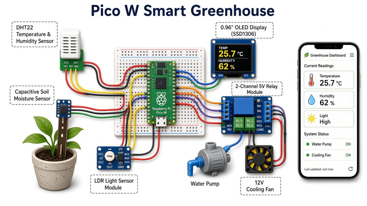
Raspberry Pi Pico W smart greenhouse wiring illustration with DHT22, soil moisture sensor, LDR, OLED, 2-channel relay, water pump, fan and phone dashboard

Build a Raspberry Pi Pico W smart greenhouse that reads temperature, humidity, soil moisture and light, waters plants and runs a fan automatically, and shows everything on an OLED and a Wi-Fi dashboard. MicroPython code, wiring and diagram.

  • DifficultyAdvanced
  • Build time5–8 hours
  • Board / MCURaspberry Pi Pico W
  • Parts11 items
  • CodeMicroPython

Need it ready-made? Buy Ready Project

This Raspberry Pi Pico W smart greenhouse watches the air temperature, humidity, soil moisture and light level around your plants and takes care of them on its own. When the soil gets dry it switches on a small water pump, and when the air gets too hot or too humid it runs a cooling fan.

Everything shows on a 0.96 inch OLED screen and on a live web dashboard that opens on any phone on your Wi-Fi. From the dashboard you can also switch the pump and fan by hand or return to automatic mode. It is a complete combination project that joins three sensors, a display, two relays and Wi-Fi, all programmed in MicroPython.

Raspberry Pi Pico W smart greenhouse wiring illustration with DHT22, soil moisture sensor, LDR, OLED, 2-channel relay, water pump, fan and phone dashboard

How It Works

  • Sensing: a DHT22 measures temperature and humidity, a capacitive soil moisture probe gives an analog voltage that the Pico reads on ADC0 (GP26), and an LDR module gives the light level on ADC1 (GP27). The raw soil reading is turned into a 0 to 100 % moisture value using two calibration numbers.
  • Pump control: the pump turns on when moisture falls below 35 % and turns off above 55 %. Two safety limits stop overwatering: the pump never runs longer than 30 seconds at a time and then waits 2 minutes so the water can soak in before the next reading.
  • Fan control: the fan starts above 32 °C or above 85 % humidity and stops below 29 °C. The gap between the on and off points (hysteresis) stops the relay from clicking on and off rapidly.
  • Display: every 2 seconds the OLED shows all four readings, the pump and fan state, and whether the system is in AUTO or MANUAL mode.
  • Web dashboard: the Pico W joins your Wi-Fi and runs a small web server with uasyncio. The page refreshes its six tiles every 3 seconds from /json. Pressing a Pump or Fan button switches to manual mode, and the Auto button hands control back to the sensors.
  • Offline safety: if Wi-Fi is not available, the greenhouse still waters and cools automatically. Only the dashboard is skipped.

Components Required

  • Raspberry Pi Pico W – 1
  • DHT22 (AM2302) temperature and humidity sensor – 1
  • 10 kΩ resistor (DHT22 pull-up, not needed on a 3-pin DHT22 module) – 1
  • Capacitive soil moisture sensor v1.2 – 1
  • LDR light sensor module (with analog AO pin) – 1
  • 0.96 inch SSD1306 I2C OLED (128×64) – 1
  • 2-channel 5 V relay module – 1
  • 5 V mini submersible water pump with tubing – 1
  • 12 V DC cooling fan – 1
  • 5 V supply for the pump and 12 V supply for the fan (or a 12 V pump on the same 12 V supply)
  • Breadboard, jumper wires, micro-USB cable and 5 V USB adapter for the Pico

Wiring Table

FromToNotes
DHT22 VCCPico 3V3 OUT (pin 36)
DHT22 DATAPico GP1510 kΩ pull-up to 3V3
DHT22 GNDPico GND
Soil sensor VCCPico 3V3 OUT
Soil sensor AOUTPico GP26 (ADC0)Analog moisture signal
Soil sensor GNDPico GND
LDR module VCCPico 3V3 OUT
LDR module AOPico GP27 (ADC1)Analog light signal
LDR module GNDPico GND
OLED VCCPico 3V3 OUT
OLED GNDPico GND
OLED SDAPico GP4I2C0 SDA
OLED SCLPico GP5I2C0 SCL, address 0x3C
Relay VCCPico VBUS (pin 40)5 V from USB
Relay GNDPico GND
Relay IN1Pico GP16Water pump channel
Relay IN2Pico GP17Cooling fan channel
Pump supply + to relay CH1 COM, CH1 NO to pump +Pump – to supply –Pump switched by relay 1
12 V + to relay CH2 COM, CH2 NO to fan +Fan – to 12 V –Fan switched by relay 2

Connection Diagram

The illustration above shows the overall layout. The pin-accurate drawing below matches the wiring table exactly, so follow it while building.

Pico W Smart Greenhouse – Pin-Accurate Wiring Raspberry Pi Pico W VBUS (pin 40): 5 V from USB to relay VCC 3V3 OUT (pin 36): DHT22, soil sensor, LDR, OLED VCC GND: common ground for all modules GP15: DHT22 DATA (10k pull-up to 3V3) GP26 / ADC0: soil sensor AOUT GP27 / ADC1: LDR module AO GP4 (SDA) / GP5 (SCL): OLED GP16: relay IN1 (pump), GP17: relay IN2 (fan) DHT22 VCC: 3V3 DATA: GP15 + 10k to 3V3 GND: GND Capacitive Soil Sensor v1.2 VCC: 3V3 AOUT: GP26 (ADC0) GND: GND LDR Light Module VCC: 3V3 AO: GP27 (ADC1) GND: GND SSD1306 OLED 0.96in VCC: 3V3 GND: GND SDA: GP4 SCL: GP5 2-Channel 5V Relay VCC: VBUS (5V), GND: GND IN1: GP16, IN2: GP17 CH1 COM/NO: in series with pump + supply CH2 COM/NO: in series with 12 V fan + supply Note: the pump and fan use their own supply through the relay contacts. Join only the grounds of the logic side.
Pin-accurate connection diagram for the Raspberry Pi Pico W smart greenhouse.

Setting Up MicroPython

  • Hold the BOOTSEL button, plug the Pico W into your computer and drag the latest Pico W MicroPython UF2 file onto the RPI-RP2 drive.
  • Open Thonny, choose the MicroPython (Raspberry Pi Pico) interpreter, and save the ssd1306.py driver from micropython-lib to the Pico.
  • Copy the code below into a new file, replace the Wi-Fi placeholders, and save it on the Pico as main.py so it runs on every power-up.

Code

# Raspberry Pi Pico W Smart Greenhouse Monitor & Controller (MicroPython)
# Sensors : DHT22 (temp/humidity), capacitive soil moisture, LDR light module
# Outputs : SSD1306 OLED, 2-channel relay (water pump + cooling fan)
# Web     : live dashboard + JSON at http://<pico-ip>/  and /json
# Needs   : ssd1306.py (from micropython-lib) copied to the Pico

import network, time, dht, json
import uasyncio as asyncio
from machine import Pin, ADC, I2C
from ssd1306 import SSD1306_I2C

# ---------- user settings ----------
WIFI_SSID = "YOUR_WIFI_SSID"          # placeholder, put your Wi-Fi name
WIFI_PASS = "YOUR_WIFI_PASSWORD"      # placeholder, put your Wi-Fi password

SOIL_DRY_RAW = 50000   # ADC reading with the probe in dry air (calibrate)
SOIL_WET_RAW = 20000   # ADC reading with the probe in a glass of water (calibrate)
SOIL_ON  = 35          # start pump below this moisture %
SOIL_OFF = 55          # stop pump above this moisture %
PUMP_MAX_S = 30        # never run the pump longer than this in one go
PUMP_REST_S = 120      # wait this long after a watering before the next one
FAN_ON_C  = 32.0       # start fan above this temperature
FAN_OFF_C = 29.0       # stop fan below this temperature
FAN_ON_RH = 85.0       # also run fan if humidity is above this
RELAY_ACTIVE_LOW = True  # most blue relay modules switch ON with a LOW input

# ---------- hardware ----------
dht_sensor = dht.DHT22(Pin(15))
soil_adc = ADC(26)                     # GP26 = ADC0
ldr_adc = ADC(27)                      # GP27 = ADC1
i2c = I2C(0, sda=Pin(4), scl=Pin(5), freq=400000)
oled = SSD1306_I2C(128, 64, i2c)
pump_pin = Pin(16, Pin.OUT)
fan_pin = Pin(17, Pin.OUT)
led = Pin("LED", Pin.OUT)              # on-board LED of the Pico W

state = {"temp": None, "hum": None, "soil": 0, "light": 0,
         "pump": False, "fan": False, "mode": "auto", "ip": "-"}
pump_started = 0
pump_stopped = -PUMP_REST_S * 1000

def set_relay(pin, on):
    # Drive a relay channel taking the module's active level into account
    pin.value(0 if (on == RELAY_ACTIVE_LOW) else 1)

def set_pump(on):
    global pump_started, pump_stopped
    if on and not state["pump"]:
        pump_started = time.ticks_ms()
    if not on and state["pump"]:
        pump_stopped = time.ticks_ms()
    state["pump"] = on
    set_relay(pump_pin, on)

def set_fan(on):
    state["fan"] = on
    set_relay(fan_pin, on)

set_pump(False)
set_fan(False)

def read_sensors():
    try:
        dht_sensor.measure()
        state["temp"] = dht_sensor.temperature()
        state["hum"] = dht_sensor.humidity()
    except OSError:
        pass  # keep last good value if one read fails
    raw = soil_adc.read_u16()
    pct = (SOIL_DRY_RAW - raw) * 100 // (SOIL_DRY_RAW - SOIL_WET_RAW)
    state["soil"] = max(0, min(100, pct))
    # LDR module output falls when light rises, so invert it to a 0-100 % light level
    state["light"] = 100 - ldr_adc.read_u16() * 100 // 65535

def auto_control():
    if state["mode"] != "auto":
        return
    now = time.ticks_ms()
    # Pump with hysteresis, maximum run time and rest time
    if state["pump"]:
        if state["soil"] >= SOIL_OFF or time.ticks_diff(now, pump_started) > PUMP_MAX_S * 1000:
            set_pump(False)
    elif state["soil"] < SOIL_ON and time.ticks_diff(now, pump_stopped) > PUMP_REST_S * 1000:
        set_pump(True)
    # Fan with hysteresis on temperature, plus high humidity
    t, h = state["temp"], state["hum"]
    if t is not None:
        if t > FAN_ON_C or (h is not None and h > FAN_ON_RH):
            set_fan(True)
        elif t < FAN_OFF_C and (h is None or h < FAN_ON_RH - 5):
            set_fan(False)

def draw_oled():
    oled.fill(0)
    oled.text("Smart Greenhouse", 0, 0)
    t = "--" if state["temp"] is None else "%.1f" % state["temp"]
    h = "--" if state["hum"] is None else "%.0f" % state["hum"]
    oled.text("Temp : %s C" % t, 0, 14)
    oled.text("Humid: %s %%" % h, 0, 24)
    oled.text("Soil : %d %%" % state["soil"], 0, 34)
    oled.text("Light: %d %%" % state["light"], 0, 44)
    oled.text("P:%s F:%s %s" % ("ON " if state["pump"] else "OFF",
                                 "ON " if state["fan"] else "OFF",
                                 state["mode"].upper()), 0, 56)
    oled.show()

PAGE = """<!DOCTYPE html><html><head><meta name=viewport content="width=device-width,initial-scale=1">
<title>Pico W Greenhouse</title><style>body{font-family:Arial;background:#eef5ee;margin:0;padding:12px}
.g{display:grid;grid-template-columns:1fr 1fr;gap:10px}.c{background:#fff;border-radius:10px;padding:12px;text-align:center}
.v{font-size:26px;font-weight:bold;color:#2e7d32}a{display:inline-block;margin:4px;padding:8px 12px;background:#2e7d32;color:#fff;border-radius:6px;text-decoration:none}</style></head>
<body><h2>Pico W Smart Greenhouse</h2><div class=g>
<div class=c>Temperature<div class=v id=temp>-</div></div><div class=c>Humidity<div class=v id=hum>-</div></div>
<div class=c>Soil moisture<div class=v id=soil>-</div></div><div class=c>Light<div class=v id=light>-</div></div>
<div class=c>Pump<div class=v id=pump>-</div></div><div class=c>Fan<div class=v id=fan>-</div></div></div>
<p>Mode: <b id=mode>-</b></p>
<a href=# onclick="go('/auto')">Auto</a><a href=# onclick="go('/pump/on')">Pump ON</a><a href=# onclick="go('/pump/off')">Pump OFF</a>
<a href=# onclick="go('/fan/on')">Fan ON</a><a href=# onclick="go('/fan/off')">Fan OFF</a>
<script>function go(u){fetch(u).then(r);return false}
function r(){fetch('/json').then(x=>x.json()).then(d=>{temp.textContent=d.temp===null?'-':d.temp.toFixed(1)+' C';
hum.textContent=d.hum===null?'-':d.hum.toFixed(0)+' %';soil.textContent=d.soil+' %';light.textContent=d.light+' %';
pump.textContent=d.pump?'ON':'OFF';fan.textContent=d.fan?'ON':'OFF';mode.textContent=d.mode})}
r();setInterval(r,3000)</script></body></html>"""

async def handle(reader, writer):
    try:
        line = await reader.readline()
        path = line.decode().split(" ")[1] if line else "/"
        while await reader.readline() not in (b"\r\n", b""):
            pass  # skip request headers
        # Manual buttons switch the mode to manual so auto logic does not undo them
        if path == "/auto":
            state["mode"] = "auto"
        elif path in ("/pump/on", "/pump/off", "/fan/on", "/fan/off"):
            state["mode"] = "manual"
            on = path.endswith("/on")
            set_pump(on) if path.startswith("/pump") else set_fan(on)
        if path == "/":
            body, ctype = PAGE, "text/html"
        else:
            body, ctype = json.dumps(state), "application/json"
        writer.write("HTTP/1.0 200 OK\r\nContent-Type: %s\r\nConnection: close\r\n\r\n" % ctype)
        writer.write(body)
        await writer.drain()
    except Exception as e:
        print("HTTP error:", e)
    finally:
        writer.close()
        await writer.wait_closed()

def connect_wifi():
    wlan = network.WLAN(network.STA_IF)
    wlan.active(True)
    wlan.connect(WIFI_SSID, WIFI_PASS)
    oled.fill(0); oled.text("Connecting Wi-Fi", 0, 24); oled.show()
    for _ in range(20):                # wait up to about 20 s
        if wlan.isconnected():
            break
        led.toggle()
        time.sleep(1)
    if wlan.isconnected():
        state["ip"] = wlan.ifconfig()[0]
        print("Dashboard: http://%s/" % state["ip"])
    else:
        print("Wi-Fi failed, running offline (auto control still works)")
    led.value(wlan.isconnected())

async def control_loop():
    while True:
        read_sensors()
        auto_control()
        draw_oled()
        await asyncio.sleep(2)         # DHT22 needs at least 2 s between reads

async def main():
    connect_wifi()
    asyncio.create_task(control_loop())
    if state["ip"] != "-":
        await asyncio.start_server(handle, "0.0.0.0", 80)
    while True:
        await asyncio.sleep(3600)

asyncio.run(main())

Calibrating the Soil Sensor

  • Run print(ADC(26).read_u16()) in the Thonny shell with the probe in dry air and note the number. Put it in SOIL_DRY_RAW.
  • Dip the probe in a glass of water up to the line and note the number again. Put it in SOIL_WET_RAW.
  • Push the probe into your plant’s soil and change SOIL_ON and SOIL_OFF to suit the plant. Succulents like it drier, leafy vegetables wetter.

Testing

  • Watch the Thonny shell: it prints the dashboard address, for example http://192.168.1.60/.
  • Breathe on the DHT22 to raise the humidity above 85 %; the fan relay should click on.
  • Pull the soil probe out into dry air; after a few seconds the pump should run for up to 30 seconds.
  • Open the dashboard on your phone, press Pump ON and Fan OFF, then press Auto to give control back.

Troubleshooting

ProblemFix
OLED stays blankCheck SDA on GP4 and SCL on GP5, and run i2c.scan(); it should show 60 (0x3C).
Temperature shows —Check the DHT22 data wire on GP15 and the 10 kΩ pull-up. Readings need at least 2 seconds between them.
Relays work the wrong way roundYour relay module is active HIGH. Set RELAY_ACTIVE_LOW = False.
Pico resets when the pump startsPower the pump from its own supply through the relay, not from the Pico, and keep the grounds of the logic side joined.
Dashboard does not openCheck the IP printed in Thonny and that your phone is on the same 2.4 GHz Wi-Fi.

Ideas to Extend

  • Add a grow light on a third relay that switches on when the light level stays low in the daytime.
  • Log readings every 10 minutes to a CSV file on the Pico’s flash or to a cloud sheet.
  • Add a water level float switch so the pump never runs with an empty tank.

ESP32 Energy Meter with PZEM-004T, OLED & Web Dashboard

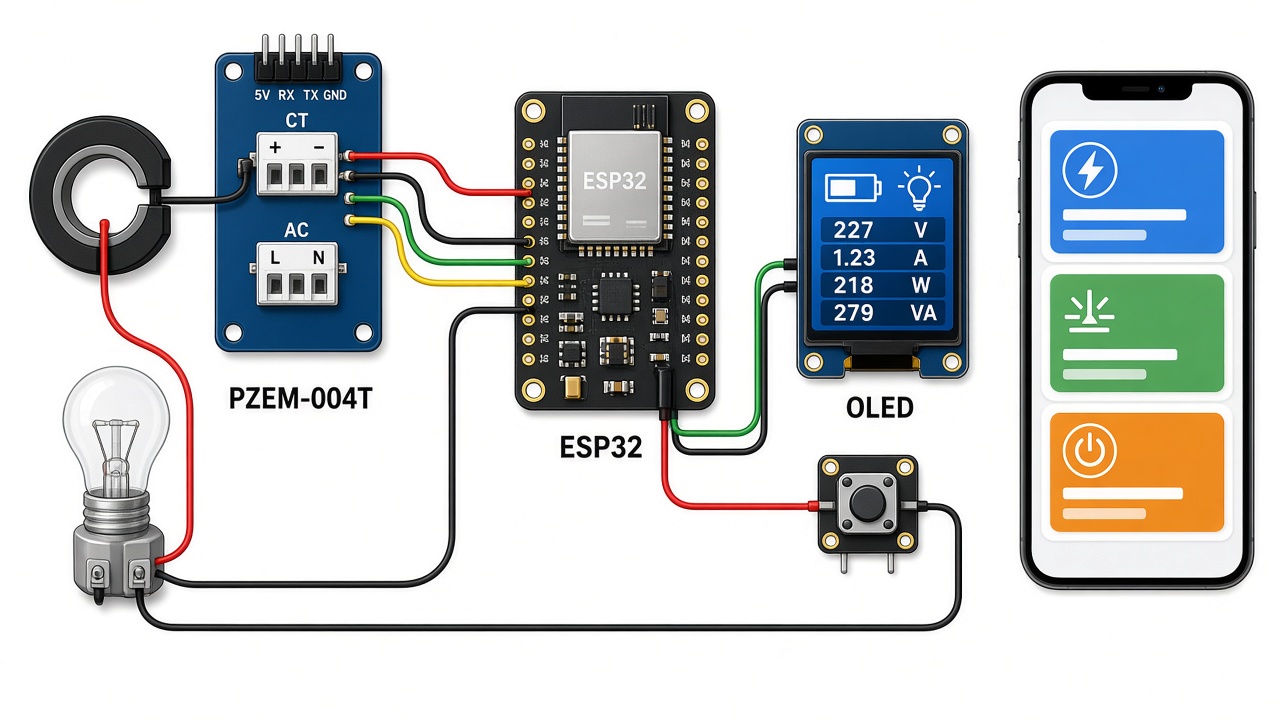
ESP32 energy meter wiring illustration with PZEM-004T module, CT coil on the live wire, OLED display, push button and phone dashboard

Build an ESP32 energy meter with a PZEM-004T v3.0 module that shows voltage, current, power, kWh and bill on an OLED and a Wi-Fi web dashboard. Wiring, diagram and full code.

  • DifficultyIntermediate
  • Build time2–4 hours
  • Board / MCUESP32 DevKit
  • Parts7 items
  • CodeArduino C++

Need it ready-made? Buy Ready Project

This ESP32 energy meter measures how much electricity an appliance or a whole room uses. A PZEM-004T v3.0 module reads the mains voltage, current, power, energy in kWh, frequency and power factor, and the ESP32 shows them on a small OLED screen and on a live web dashboard that opens on any phone connected to your Wi-Fi.

It also estimates your electricity bill from the units used, so you can see what your fridge, geyser or AC really costs to run. A JSON endpoint lets you log the data in Home Assistant, Node-RED or a spreadsheet.

ESP32 energy meter wiring illustration with PZEM-004T module, CT coil on the live wire, OLED display, push button and phone dashboard

How It Works

  • Measurement: the PZEM-004T senses voltage directly from its L and N terminals and current through its CT (current transformer) coil clamped around the live wire. Its own chip calculates power, energy, frequency and power factor and keeps the kWh count even when the ESP32 restarts.
  • Communication: the module talks Modbus RTU over a TTL serial port at 9600 baud. The ESP32 uses its second hardware serial port (UART2 on GPIO16 and GPIO17) so the USB serial monitor stays free for debugging.
  • Display: once per second the ESP32 reads all six values and draws them on the 0.96 inch SSD1306 OLED, with the power in large digits and a HIGH LOAD warning above 2000 W.
  • Web dashboard: the ESP32 runs a small web server. Open its IP address in a browser to see six live tiles that refresh every 3 seconds, the estimated bill, and a button to reset the kWh counter. /json returns the same data for other software.
  • Reset button: holding the push button on GPIO4 for 3 seconds clears the energy counter stored in the PZEM module, for example at the start of each billing month.

Components Required

  • ESP32 development board (ESP32 Dev Module / DevKit V1) – 1
  • PZEM-004T v3.0 module with 100 A split or closed CT coil – 1
  • 0.96 inch SSD1306 I2C OLED (128×64) – 1
  • Push button – 1
  • 5 V USB power adapter and micro-USB cable
  • Jumper wires, plastic enclosure, screw terminals
  • Mains cable with plug and socket for the load you want to measure

Wiring Table

FromToNotes
PZEM 5VESP32 VIN (5V)Powers the PZEM TTL interface
PZEM GNDESP32 GND
PZEM TXESP32 GPIO16 (RX2)Serial data from meter
PZEM RXESP32 GPIO17 (TX2)Serial data to meter
OLED VCCESP32 3V3
OLED GNDESP32 GND
OLED SDAESP32 GPIO21
OLED SCLESP32 GPIO22I2C address 0x3C
Push button leg 1ESP32 GPIO4Internal pull-up, hold 3 s to reset kWh
Push button leg 2ESP32 GND
PZEM L / N terminalsMains Live / Neutral230 V AC, power OFF while wiring
CT coilAround the LIVE wire to the loadOnly one wire passes through the coil

Connection Diagram

The illustration above shows the general layout. The pin-accurate drawing below matches the wiring table exactly, so follow it when you build the circuit.

ESP32 Energy Meter with PZEM-004T – Pin-Accurate Wiring ESP32 Dev Module VIN (5V): PZEM 5V and USB supply 3V3: OLED VCC GND: PZEM GND, OLED GND, button GPIO16 (RX2): PZEM TX GPIO17 (TX2): PZEM RX GPIO21 (SDA): OLED SDA GPIO22 (SCL): OLED SCL GPIO4: reset push button PZEM-004T v3.0 (TTL side) 5V: ESP32 VIN (5V) GND: ESP32 GND TX: ESP32 GPIO16 RX: ESP32 GPIO17 PZEM-004T (mains side) L and N terminals: mains Live and Neutral (voltage sense) CT coil: clamp around the LIVE wire only, going to the load SSD1306 OLED 0.96in VCC: 3V3 GND: GND SDA: GPIO21 SCL: GPIO22 Push Button Leg 1: GPIO4 (internal pull-up) Leg 2: GND Warning: the PZEM mains terminals carry 230 V AC. Wire them with the power OFF and keep them inside a closed box.
Pin-accurate connection diagram for the ESP32 PZEM-004T energy meter.

Safety First

  • The L and N terminals of the PZEM-004T are connected to 230 V mains. Make all connections with the main switch OFF and the plug removed.
  • Put the PZEM module and its mains terminals inside a closed plastic box. Never touch the board while it is powered from mains.
  • Pass only the live wire through the CT coil. If both live and neutral pass through it, the current cancels out and reads zero.
  • If you are not comfortable with mains wiring, ask a qualified electrician to do the mains side.

Code

In the Arduino IDE install the ESP32 board package and these libraries from the Library Manager: PZEM004Tv30 (by Jakub Mandula), Adafruit SSD1306 and Adafruit GFX. Choose ESP32 Dev Module as the board, replace the Wi-Fi placeholders, set your tariff in COST_PER_KWH, and upload.

/*
  ESP32 Energy Meter with PZEM-004T v3.0, OLED and Web Dashboard
  ---------------------------------------------------------------
  - Reads voltage, current, power, energy (kWh), frequency and power factor
    from a PZEM-004T v3.0 module over Modbus (UART2: GPIO16 RX, GPIO17 TX).
  - Shows live values on a 0.96" SSD1306 I2C OLED (SDA GPIO21, SCL GPIO22).
  - Serves a web dashboard on your Wi-Fi with auto-refresh and a JSON API.
  - Push button on GPIO4 (hold 3 s) or the web button resets the kWh counter.
  - Estimates the bill using your price per unit (edit COST_PER_KWH).

  Libraries: PZEM004Tv30 (by Jakub Mandula), Adafruit SSD1306, Adafruit GFX.
  Board: ESP32 Dev Module.
*/
#include <WiFi.h>
#include <WebServer.h>
#include <Wire.h>
#include <Adafruit_GFX.h>
#include <Adafruit_SSD1306.h>
#include <PZEM004Tv30.h>

// ---------- User settings ----------
const char* WIFI_SSID     = "YOUR_WIFI_SSID";      // placeholder
const char* WIFI_PASSWORD = "YOUR_WIFI_PASSWORD";  // placeholder
const float COST_PER_KWH  = 7.0;    // your electricity tariff per unit (kWh)
const float POWER_ALERT_W = 2000.0; // OLED shows "HIGH LOAD" above this

// ---------- Pins ----------
#define PZEM_RX_PIN 16   // ESP32 RX2  <- PZEM TX
#define PZEM_TX_PIN 17   // ESP32 TX2  -> PZEM RX
#define RESET_BTN   4    // push button to GND (internal pull-up)

PZEM004Tv30 pzem(Serial2, PZEM_RX_PIN, PZEM_TX_PIN);
Adafruit_SSD1306 display(128, 64, &Wire, -1);
WebServer server(80);

// Latest readings (NAN means "no reading")
float voltage = NAN, current = NAN, power = NAN, energy = NAN, freq = NAN, pf = NAN;
unsigned long lastRead = 0;
unsigned long btnPressedAt = 0;

// Read every value from the PZEM module
void readPzem() {
  voltage = pzem.voltage();
  current = pzem.current();
  power   = pzem.power();
  energy  = pzem.energy();
  freq    = pzem.frequency();
  pf      = pzem.pf();
  if (isnan(voltage)) {
    Serial.println("PZEM not responding - check wiring and mains connection");
  } else {
    Serial.printf("V=%.1f I=%.3f P=%.1f E=%.3f F=%.1f PF=%.2f\n",
                  voltage, current, power, energy, freq, pf);
  }
}

// Draw the readings on the OLED
void drawOled() {
  display.clearDisplay();
  display.setTextColor(SSD1306_WHITE);
  display.setTextSize(1);
  display.setCursor(0, 0);
  if (isnan(voltage)) {
    display.println("PZEM-004T");
    display.println("No reading.");
    display.println("Check wiring/mains.");
  } else {
    display.setTextSize(2);
    display.printf("%.0fW\n", power);          // big power value
    display.setTextSize(1);
    display.printf("%.1fV  %.2fA\n", voltage, current);
    display.printf("%.3f kWh\n", energy);
    display.printf("PF %.2f  %.1fHz\n", pf, freq);
    display.printf("Bill: Rs %.2f\n", energy * COST_PER_KWH);
    if (power > POWER_ALERT_W) display.print("!! HIGH LOAD !!");
  }
  // Small Wi-Fi indicator in the top right corner
  display.setTextSize(1);
  display.setCursor(104, 0);
  display.print(WiFi.status() == WL_CONNECTED ? "WiFi" : "----");
  display.display();
}

// Helper: number to text, "--" when the value is missing
String num(float v, int digits) {
  return isnan(v) ? String("--") : String(v, digits);
}

// Web dashboard page (refreshes itself every 3 seconds)
void handleRoot() {
  String html = F("<!DOCTYPE html><html><head><meta name='viewport' content='width=device-width,initial-scale=1'>"
                  "<meta http-equiv='refresh' content='3'><title>ESP32 Energy Meter</title>"
                  "<style>body{font-family:Arial;background:#f4f6f8;text-align:center}"
                  ".g{display:grid;grid-template-columns:repeat(2,1fr);gap:10px;max-width:420px;margin:auto}"
                  ".c{background:#fff;border-radius:10px;padding:14px;box-shadow:0 1px 4px #0002}"
                  ".v{font-size:26px;font-weight:bold;color:#1565c0}button{margin-top:16px;padding:10px 18px}</style>"
                  "</head><body><h2>ESP32 Energy Meter</h2><div class='g'>");
  html += "<div class='c'>Voltage<div class='v'>" + num(voltage, 1) + " V</div></div>";
  html += "<div class='c'>Current<div class='v'>" + num(current, 3) + " A</div></div>";
  html += "<div class='c'>Power<div class='v'>" + num(power, 1) + " W</div></div>";
  html += "<div class='c'>Energy<div class='v'>" + num(energy, 3) + " kWh</div></div>";
  html += "<div class='c'>Frequency<div class='v'>" + num(freq, 1) + " Hz</div></div>";
  html += "<div class='c'>Power factor<div class='v'>" + num(pf, 2) + "</div></div>";
  html += "</div><p>Estimated bill: <b>Rs " + num(isnan(energy) ? NAN : energy * COST_PER_KWH, 2) + "</b></p>";
  html += F("<form action='/reset' method='POST' onsubmit=\"return confirm('Reset kWh counter?')\">"
            "<button>Reset energy counter</button></form></body></html>");
  server.send(200, "text/html", html);
}

// JSON API for Home Assistant, Node-RED or a spreadsheet logger
void handleJson() {
  String j = "{\"voltage\":" + num(voltage, 1) + ",\"current\":" + num(current, 3) +
             ",\"power\":" + num(power, 1) + ",\"energy\":" + num(energy, 3) +
             ",\"frequency\":" + num(freq, 1) + ",\"pf\":" + num(pf, 2) + "}";
  j.replace("--", "null");
  server.send(200, "application/json", j);
}

// Reset the kWh counter stored inside the PZEM module
void handleReset() {
  bool ok = pzem.resetEnergy();
  Serial.println(ok ? "Energy counter reset" : "Energy reset failed");
  server.sendHeader("Location", "/");
  server.send(303);
}

void connectWiFi() {
  WiFi.mode(WIFI_STA);
  WiFi.begin(WIFI_SSID, WIFI_PASSWORD);
  Serial.print("Connecting to Wi-Fi");
  unsigned long start = millis();
  while (WiFi.status() != WL_CONNECTED && millis() - start < 15000) {
    delay(500);
    Serial.print(".");
  }
  Serial.println();
  if (WiFi.status() == WL_CONNECTED) {
    Serial.print("Dashboard: http://");
    Serial.println(WiFi.localIP());
  } else {
    Serial.println("Wi-Fi not connected, OLED still works. Will retry.");
  }
}

void setup() {
  Serial.begin(115200);
  pinMode(RESET_BTN, INPUT_PULLUP);

  if (!display.begin(SSD1306_SWITCHCAPVCC, 0x3C)) {
    Serial.println("OLED not found at 0x3C");
  }
  display.clearDisplay();
  display.setTextColor(SSD1306_WHITE);
  display.setCursor(0, 0);
  display.println("ESP32 Energy Meter");
  display.println("Connecting Wi-Fi...");
  display.display();

  connectWiFi();
  if (WiFi.status() == WL_CONNECTED) {
    display.println(WiFi.localIP());
    display.display();
    delay(2000);
  }

  server.on("/", handleRoot);
  server.on("/json", handleJson);
  server.on("/reset", HTTP_POST, handleReset);
  server.begin();
}

void loop() {
  server.handleClient();

  // Read the meter and refresh the OLED once per second
  if (millis() - lastRead >= 1000) {
    lastRead = millis();
    readPzem();
    drawOled();
  }

  // Hold the button for 3 seconds to reset the kWh counter
  if (digitalRead(RESET_BTN) == LOW) {
    if (btnPressedAt == 0) btnPressedAt = millis();
    if (millis() - btnPressedAt > 3000) {
      pzem.resetEnergy();
      Serial.println("Energy counter reset by button");
      btnPressedAt = 0;
      while (digitalRead(RESET_BTN) == LOW) delay(10);  // wait for release
    }
  } else {
    btnPressedAt = 0;
  }

  // Reconnect Wi-Fi every 30 s if the router dropped
  static unsigned long lastWifiTry = 0;
  if (WiFi.status() != WL_CONNECTED && millis() - lastWifiTry > 30000) {
    lastWifiTry = millis();
    WiFi.disconnect();
    WiFi.begin(WIFI_SSID, WIFI_PASSWORD);
  }
}

Testing

  • Open the Serial Monitor at 115200 baud. It prints the dashboard address, for example http://192.168.1.50.
  • With mains connected and no load, voltage should read about 220 to 240 V and current close to 0 A.
  • Plug in a known load, such as a 100 W bulb or a 1000 W kettle, and check that the power reading is close to its rating.
  • Open the dashboard on your phone and watch the tiles refresh every 3 seconds.

Troubleshooting

ProblemFix
OLED says No readingThe PZEM needs mains on its L and N terminals to answer. Also check that TX goes to GPIO16 and RX to GPIO17 (crossed).
Current reads 0 A with a load onMake sure only the live wire passes through the CT coil and the coil plug is fully inserted.
Dashboard does not openCheck the IP in the Serial Monitor and that your phone is on the same Wi-Fi network.
Readings freeze sometimesUse a good 5 V 1 A adapter and keep the serial wires short.

Ideas to Extend

  • Log the JSON data every minute to Google Sheets or InfluxDB and plot daily usage.
  • Add a relay to switch off the load automatically when power goes above a limit.
  • Use several PZEM modules with different Modbus addresses to monitor each circuit of the house.

Wemos D1 Mini Wi-Fi Doorbell with Phone Alerts (ntfy)

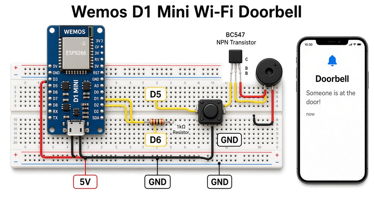
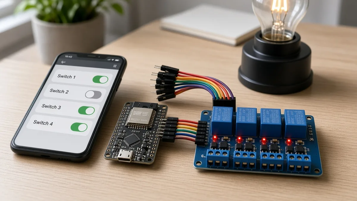
Wemos D1 Mini Wi-Fi doorbell breadboard wiring with push button on D5, BC547 buzzer driver on D6 and phone notification

Build a Wemos D1 Mini Wi-Fi doorbell that rings a buzzer and sends a push notification to your phone through ntfy.sh. Wiring table, diagram and full code.

  • DifficultyEasy
  • Build time1–2 hours
  • Board / MCUWemos D1 Mini (ESP8266)
  • Parts8 items
  • CodeArduino C++

Need it ready-made? Buy Ready Project

This Wemos D1 Mini Wi-Fi doorbell turns a simple push button into a smart doorbell. When a visitor presses the button, a buzzer rings at the door and your phone gets a push notification within a second or two, even if you are upstairs or away from home.

The alert is sent through ntfy.sh, a free push notification service that needs no account, no API key and no app server of your own. You just install the free ntfy app on Android or iPhone and subscribe to a topic name that you choose.

Wemos D1 Mini Wi-Fi doorbell breadboard wiring with push button on D5, BC547 buzzer driver on D6 and phone notification

How It Works

  • Button: the doorbell button connects D5 to GND. The ESP8266 internal pull-up keeps D5 HIGH, so a press reads as LOW. The code debounces the press for 50 ms so one press counts once.
  • Buzzer: the D1 Mini pin can only supply a few milliamps, so it switches a BC547 transistor through a 1 kΩ resistor. The transistor connects the 5 V active buzzer to ground and it plays a short ding-dong.
  • Wi-Fi alert: right after the ring, the board sends an HTTPS POST to https://ntfy.sh/your-topic with a title, a high priority and a bell icon. The ntfy app on your phone shows it as a normal notification.
  • Cooldown: if someone presses the button again and again, the buzzer still rings but only one phone alert is sent every 10 seconds, so your phone is not flooded.
  • Status LED: the built-in LED blinks while Wi-Fi connects and lights while an alert is being sent. The board reconnects to Wi-Fi by itself if the router restarts.

Components Required

  • Wemos D1 Mini (ESP8266) – 1
  • Push button (doorbell switch or 12 mm tactile button) – 1
  • 5 V active buzzer – 1
  • BC547 NPN transistor – 1
  • 1 kΩ resistor – 1
  • 5 V USB power adapter with micro-USB cable
  • Breadboard or small perfboard, jumper wires
  • Two-core wire to run the button to the door (optional)

Wiring Table

FromToNotes
Button leg 1D1 Mini D5 (GPIO14)Internal pull-up used, no resistor needed
Button leg 2D1 Mini GND
D1 Mini D6 (GPIO12)1 kΩ resistor, then BC547 baseSwitches the transistor
BC547 emitterD1 Mini GND
BC547 collectorBuzzer – (short leg)Low side switch
Buzzer + (long leg)D1 Mini 5V pin5 V from USB
D1 Mini micro-USB5 V adapterPowers the whole circuit
D4 (GPIO2)Built-in LEDStatus light, no wiring needed

Connection Diagram

The illustration above shows the general breadboard layout. The pin-accurate drawing below matches the wiring table exactly, so follow it when you build the circuit.

Wemos D1 Mini Wi-Fi Doorbell – Pin-Accurate Wiring Wemos D1 Mini 5V pin: USB 5 V supply (buzzer +) GND pin: common ground D5 (GPIO14): push button D6 (GPIO12): 1 kΩ to BC547 base D4 (GPIO2): built-in status LED Doorbell Button Leg 1: D5 (internal pull-up enabled) Leg 2: GND BC547 Driver Base (B): 1 kΩ from D6 Emitter (E): GND Collector (C): buzzer – (negative) Active Buzzer 5 V + (long leg): 5V pin – (short leg): BC547 collector Signal flow: button press on D5, buzzer rings through BC547 on D6, Wi-Fi sends an HTTPS alert to ntfy.sh, phone shows it.
Pin-accurate connection diagram for the Wemos D1 Mini Wi-Fi doorbell.

Setting Up the Phone Alerts

  • Install the free ntfy app from the Play Store or App Store.
  • Tap the + button and subscribe to a topic name, for example raj-home-doorbell-7k29. Use a long, hard-to-guess name, because anyone who knows the topic can read it.
  • Put the same topic name in NTFY_TOPIC in the code below.

Code

Install the ESP8266 board package in the Arduino IDE (Boards Manager, search “esp8266”), choose LOLIN(WEMOS) D1 R2 & mini as the board, replace the Wi-Fi and topic placeholders, and upload. No extra libraries are needed.

/*
  Wemos D1 Mini Wi-Fi Doorbell with ntfy Phone Alerts
  ---------------------------------------------------
  - Press the doorbell button: the buzzer rings and a push
    notification is sent to your phone through ntfy.sh.
  - Install the free "ntfy" app on your phone and subscribe
    to the same topic name you set below.

  Wiring (see the wiring table in the post):
    Push button : D5 (GPIO14) to GND  (internal pull-up used)
    Buzzer      : D6 (GPIO12) -> 1k -> BC547 base, buzzer on collector
    Status LED  : built-in LED on D4 (GPIO2, active LOW)
*/

#include <ESP8266WiFi.h>
#include <ESP8266HTTPClient.h>
#include <WiFiClientSecure.h>

// ---------- User settings (replace the placeholders) ----------
const char* WIFI_SSID     = "YOUR_WIFI_SSID";
const char* WIFI_PASSWORD = "YOUR_WIFI_PASSWORD";
// Pick a long, hard-to-guess topic name. Anyone who knows it can read it.
const char* NTFY_TOPIC    = "YOUR_UNIQUE_DOORBELL_TOPIC";
// ---------------------------------------------------------------

const uint8_t BUTTON_PIN = D5;   // GPIO14
const uint8_t BUZZER_PIN = D6;   // GPIO12 (drives BC547)
const uint8_t LED_PIN    = LED_BUILTIN; // GPIO2, LOW = ON

const unsigned long DEBOUNCE_MS = 50;     // ignore contact bounce
const unsigned long COOLDOWN_MS = 10000;  // max one alert every 10 s

unsigned long lastAlert = 0;
bool lastReading = HIGH;
bool stableState = HIGH;
unsigned long lastChange = 0;

// Ring the buzzer in a simple "ding-dong" pattern
void ringBuzzer() {
  for (int i = 0; i < 2; i++) {
    digitalWrite(BUZZER_PIN, HIGH);
    delay(300);
    digitalWrite(BUZZER_PIN, LOW);
    delay(150);
  }
}

// Connect (or reconnect) to Wi-Fi, blinking the LED while waiting
void connectWiFi() {
  if (WiFi.status() == WL_CONNECTED) return;
  Serial.print("Connecting to Wi-Fi");
  WiFi.mode(WIFI_STA);
  WiFi.begin(WIFI_SSID, WIFI_PASSWORD);
  unsigned long start = millis();
  while (WiFi.status() != WL_CONNECTED && millis() - start < 20000) {
    digitalWrite(LED_PIN, !digitalRead(LED_PIN));
    delay(250);
    Serial.print(".");
  }
  digitalWrite(LED_PIN, HIGH); // LED off
  Serial.println(WiFi.status() == WL_CONNECTED ? " connected" : " failed");
}

// Send a push notification through ntfy.sh (HTTPS POST)
bool sendNotification() {
  connectWiFi();
  if (WiFi.status() != WL_CONNECTED) return false;

  WiFiClientSecure client;
  client.setInsecure();          // skip certificate check (simple setup)
  HTTPClient http;
  String url = String("https://ntfy.sh/") + NTFY_TOPIC;
  if (!http.begin(client, url)) return false;

  http.addHeader("Title", "Doorbell");
  http.addHeader("Priority", "high");
  http.addHeader("Tags", "bell");
  int code = http.POST("Someone is at the door!");
  http.end();

  Serial.printf("ntfy response: %d\n", code);
  return code == 200;
}

void setup() {
  Serial.begin(115200);
  pinMode(BUTTON_PIN, INPUT_PULLUP);
  pinMode(BUZZER_PIN, OUTPUT);
  pinMode(LED_PIN, OUTPUT);
  digitalWrite(BUZZER_PIN, LOW);
  digitalWrite(LED_PIN, HIGH);
  connectWiFi();
}

void loop() {
  // --- Debounce the button ---
  bool reading = digitalRead(BUTTON_PIN);
  if (reading != lastReading) {
    lastChange = millis();
    lastReading = reading;
  }
  if (millis() - lastChange > DEBOUNCE_MS && reading != stableState) {
    stableState = reading;

    // Button pressed (pin pulled LOW)
    if (stableState == LOW) {
      ringBuzzer();
      if (millis() - lastAlert > COOLDOWN_MS || lastAlert == 0) {
        lastAlert = millis();
        digitalWrite(LED_PIN, LOW);           // LED on while sending
        bool ok = sendNotification();
        digitalWrite(LED_PIN, HIGH);
        Serial.println(ok ? "Alert sent" : "Alert failed");
      }
    }
  }

  // Keep Wi-Fi alive in the background
  if (WiFi.status() != WL_CONNECTED) connectWiFi();
}

Testing

  • Open the Serial Monitor at 115200 baud and check that it prints “connected”.
  • Press the button. The buzzer should play two beeps and the monitor should show “ntfy response: 200” and “Alert sent”.
  • Your phone should show a Doorbell notification saying “Someone is at the door!”
  • Press again within 10 seconds: the buzzer rings but no second alert is sent.

Troubleshooting

ProblemFix
No notification on the phoneCheck that the topic in the app and in the code match exactly, and that the phone has internet.
ntfy response is -1The board could not reach ntfy.sh. Check the Wi-Fi name and password and that the router has internet.
Buzzer does not soundCheck the transistor pins (E, B, C) and use an active buzzer, not a passive one.
One press gives two alertsIncrease DEBOUNCE_MS to 100 or use a better quality button.

Ideas to Extend

  • Add an ESP32-CAM so the alert includes a photo of the visitor.
  • Run the board on an 18650 cell with deep sleep so it works without a wall adapter.
  • Send the alert to a self-hosted ntfy server on your own network for full privacy.

ATmega16 Bluetooth Home Automation with HC-05, 4 Relays & LCD

ATmega16 Bluetooth home automation connection diagram with HC-05, 16x2 LCD, 4-channel relay module, buttons and 7805 regulator

Build an ATmega16 Bluetooth home automation system with HC-05, a 4-channel relay module, 16×2 LCD and manual buttons. Wiring table, diagram and full AVR C code.

  • DifficultyAdvanced
  • Build time5–8 hours
  • Board / MCUATmega16
  • Parts12 items
  • CodeAVR C

Need it ready-made? Buy Ready Project

This ATmega16 Bluetooth home automation project lets you switch four home appliances ON and OFF from your Android phone using an HC-05 Bluetooth module, a 4-channel relay module and a 16×2 LCD that shows the live status of every relay. Four push buttons on the board also work as manual switches, so the lights still work even when the phone is not connected.

It is a big combination project: it uses the ATmega16 hardware UART with an interrupt, a 4-bit LCD driver written from scratch, debounced buttons and relay control, all in plain AVR C with no Arduino libraries. It is a great step up for students who already know basic AVR programming.

How the Bluetooth Home Automation Works

  • Phone to HC-05: a free Bluetooth terminal app on the phone sends single characters. The HC-05 receives them over Bluetooth and passes them to the ATmega16 over serial at 9600 baud.
  • UART interrupt: every received byte triggers the USART_RXC interrupt, which stores it. The main loop reads it and decides what to do.
  • Commands: 1–4 turn relay 1–4 ON, a–d turn them OFF, A turns all ON, Z turns all OFF and S sends the status back to the phone.
  • Manual buttons: SW1–SW4 on PA0–PA3 toggle the matching relay. The code uses internal pull-ups and a 30 ms software debounce.
  • LCD feedback: the 16×2 LCD shows R1 to R4 on the first line and ON or OFF under each one. Every change is also sent back to the phone.
  • Relay driver: the relay module has its own transistor and opto-coupler, so the ATmega16 pins drive the IN pins directly. Most modules are active LOW, which is set with RELAY_ACTIVE_LOW.

Components Required

  • ATmega16 / ATmega16A microcontroller (DIP-40) – 1
  • HC-05 Bluetooth module – 1
  • 4-channel 5 V relay module (opto-isolated) – 1
  • 16×2 character LCD (HD44780) – 1
  • 10 kΩ potentiometer (LCD contrast) – 1
  • 16 MHz crystal and 2 × 22 pF capacitors
  • Tactile push buttons – 4
  • Resistors: 1 kΩ, 2 kΩ (HC-05 RX divider), 10 kΩ (reset pull-up), 330 Ω (LED)
  • Status LED – 1
  • 7805 voltage regulator with 10 µF and 100 µF capacitors, plus 100 nF decoupling capacitors
  • 12 V DC adapter (1 A) and DC jack
  • USBasp programmer, breadboard or perfboard, jumper wires

Wiring Table (Pin-to-Pin)

Part / PinATmega16 pinNotes
HC-05 TXDPD0 / RXD (pin 14)Data from phone to MCU
HC-05 RXDPD1 / TXD (pin 15)Through 1 kΩ, with 2 kΩ from HC-05 RXD to GND (5 V to 3.3 V divider)
HC-05 VCC / GND+5 V / GNDThe HC-05 board has its own 3.3 V regulator
LCD RSPC0 (pin 22)Register select
LCD EPC1 (pin 23)Enable
LCD D4, D5, D6, D7PC2, PC3, PC4, PC5 (pins 24–27)4-bit data bus
LCD RWGNDWrite only
LCD V010 kΩ pot wiperPot ends to +5 V and GND
LCD VSS / VDD / A / KGND / +5 V / +5 V (via 220 Ω) / GNDPower and backlight
Relay IN1, IN2, IN3, IN4PB0, PB1, PB2, PB3 (pins 1–4)Relay VCC to +5 V, GND to GND
SW1, SW2, SW3, SW4PA0, PA1, PA2, PA3 (pins 40, 39, 38, 37)Other leg of each button to GND
Status LEDPD7 (pin 21)Through 330 Ω to GND
16 MHz crystalXTAL1 (12) and XTAL2 (13)22 pF from each pin to GND
VCC, AVCCPins 10 and 30+5 V from 7805, 100 nF to GND near each pin
GNDPins 11 and 31Common ground for all modules
RESETPin 910 kΩ pull-up to +5 V

Connection Diagram

The picture below gives an overview of the whole build. The pin-accurate drawing after it matches the wiring table and the code exactly, so follow the table and that drawing when you wire the board.

ATmega16 Bluetooth home automation connection diagram with HC-05, 16x2 LCD, 4-channel relay module, buttons and 7805 regulator
ATmega16 Bluetooth Home Automation – Pin-Accurate Wiring ATmega16 (DIP-40) PD0 (RXD, pin 14) HC-05 TXD PD1 (TXD, pin 15) 1 kΩ → HC-05 RXD (2 kΩ from RXD to GND) PC0 / PC1 (pins 22, 23) LCD RS / E PC2–PC5 (pins 24–27) LCD D4–D7 (RW → GND, 10 kΩ pot → V0) PB0–PB3 (pins 1–4) Relay module IN1–IN4 PA0–PA3 (pins 40–37) Buttons SW1–SW4 → GND (internal pull-ups) PD7 (pin 21) 330 Ω → status LED → GND XTAL1 / XTAL2 (12, 13) 16 MHz crystal + 22 pF to GND on each pin VCC, AVCC (10, 30) +5 V from 7805 (100 nF to GND) GND (11, 31) Common GND: HC-05, LCD, relays, 7805 RESET (pin 9) 10 kΩ to +5 V Relay module VCC: +5 V (7805 rated 1 A, add a heatsink). Mains wiring only by a qualified person.
Pin-accurate connection diagram for the ATmega16 Bluetooth home automation.

ATmega16 Code (AVR C)

Create a new GCC C project for the ATmega16 in Microchip Studio (or use avr-gcc), paste the code and build it. Flash the HEX with a USBasp and set the fuses to lfuse 0xFF and hfuse 0xD9 for the 16 MHz external crystal with JTAG disabled. The code is fully commented and compiles without errors for the ATmega16 (about 1 KB of flash).

/*
  ATmega16 Bluetooth Home Automation
  HC-05 Bluetooth + 4-channel relay module + 16x2 LCD (4-bit) + 4 manual buttons
  Compiler : AVR-GCC (Microchip Studio, or avr-gcc + avrdude)
  Clock    : 16 MHz external crystal  (fuses: lfuse 0xFF, hfuse 0xD9 - JTAG disabled)

  Wiring
    HC-05 TXD -> PD0 (RXD)      HC-05 RXD <- PD1 (TXD) through 1k/2k divider
    LCD RS -> PC0   E -> PC1   D4..D7 -> PC2..PC5   RW -> GND
    Relay IN1..IN4 -> PB0..PB3
    Buttons SW1..SW4 -> PA0..PA3 to GND (internal pull-ups)
    Status LED -> PD7 (330 ohm)

  Bluetooth commands (send from any "Bluetooth Terminal" phone app, 9600 baud)
    '1'..'4'  turn relay 1..4 ON
    'a'..'d'  turn relay 1..4 OFF
    'A'       all ON        'Z'  all OFF
    'S'       send status back to the phone
*/

#define F_CPU 16000000UL
#include <avr/io.h>
#include <avr/interrupt.h>
#include <util/delay.h>
#include <stdint.h>

#define BAUD 9600
#define UBRR_VALUE ((F_CPU / 16UL / BAUD) - 1)

#define RELAY_ACTIVE_LOW 1      // most blue relay modules switch ON when IN is LOW

#define LCD_RS PC0
#define LCD_E  PC1
#define LED_PIN PD7

static volatile uint8_t rx_char = 0;    // last character received (0 = none)
static uint8_t relay_state = 0;         // bit0..bit3 = relay 1..4 (1 = ON)

/* ---------------- LCD (4-bit, PORTC) ---------------- */
static void lcd_nibble(uint8_t n) {
  PORTC = (PORTC & 0xC3) | ((n & 0x0F) << 2);   // D4..D7 on PC2..PC5
  PORTC |= (1 << LCD_E);
  _delay_us(1);
  PORTC &= ~(1 << LCD_E);
  _delay_us(50);
}

static void lcd_send(uint8_t value, uint8_t is_data) {
  if (is_data) PORTC |= (1 << LCD_RS); else PORTC &= ~(1 << LCD_RS);
  lcd_nibble(value >> 4);
  lcd_nibble(value);
  if (!is_data && value < 4) _delay_ms(2);        // clear and home need more time
}

static void lcd_cmd(uint8_t c)  { lcd_send(c, 0); }
static void lcd_char(char c)    { lcd_send((uint8_t)c, 1); }
static void lcd_print(const char *s) { while (*s) lcd_char(*s++); }
static void lcd_goto(uint8_t row, uint8_t col) { lcd_cmd(0x80 | (row ? 0x40 : 0x00) | col); }

static void lcd_init(void) {
  DDRC |= 0x3F;                  // PC0..PC5 outputs
  _delay_ms(50);                 // LCD power-up time
  PORTC &= ~(1 << LCD_RS);
  lcd_nibble(0x03); _delay_ms(5);
  lcd_nibble(0x03); _delay_ms(1);
  lcd_nibble(0x03);
  lcd_nibble(0x02);              // 4-bit mode
  lcd_cmd(0x28);                 // 2 lines, 5x8 font
  lcd_cmd(0x0C);                 // display on, cursor off
  lcd_cmd(0x06);                 // auto-increment
  lcd_cmd(0x01);                 // clear
}

/* ---------------- UART (HC-05) ---------------- */
static void uart_init(void) {
  UBRRH = (uint8_t)(UBRR_VALUE >> 8);
  UBRRL = (uint8_t)UBRR_VALUE;
  UCSRB = (1 << RXEN) | (1 << TXEN) | (1 << RXCIE);       // RX, TX, RX interrupt
  UCSRC = (1 << URSEL) | (1 << UCSZ1) | (1 << UCSZ0);     // 8 data bits, 1 stop, no parity
}

static void uart_putc(char c) {
  while (!(UCSRA & (1 << UDRE)));  // wait until the transmit buffer is empty
  UDR = c;
}

static void uart_print(const char *s) { while (*s) uart_putc(*s++); }

ISR(USART_RXC_vect) {
  rx_char = UDR;                   // store the byte; main loop handles it
}

/* ---------------- Relays ---------------- */
static void relays_apply(void) {
  uint8_t out = relay_state & 0x0F;
  if (RELAY_ACTIVE_LOW) out = (~out) & 0x0F;
  PORTB = (PORTB & 0xF0) | out;    // PB0..PB3
}

static void show_status(void) {
  // Line 1: "R1 R2 R3 R4", line 2: "ON OF ON OF"
  lcd_goto(0, 0);
  lcd_print("R1  R2  R3  R4  ");
  lcd_goto(1, 0);
  for (uint8_t i = 0; i < 4; i++) {
    lcd_print((relay_state & (1 << i)) ? "ON  " : "OFF ");
  }
}

static void send_status(void) {
  uart_print("Status: ");
  for (uint8_t i = 0; i < 4; i++) {
    uart_putc('R'); uart_putc('1' + i); uart_putc('=');
    uart_print((relay_state & (1 << i)) ? "ON " : "OFF ");
  }
  uart_print("\r\n");
}

static void handle_command(char c) {
  if (c >= '1' && c <= '4')      relay_state |=  (1 << (c - '1'));
  else if (c >= 'a' && c <= 'd') relay_state &= ~(1 << (c - 'a'));
  else if (c == 'A')             relay_state = 0x0F;
  else if (c == 'Z')             relay_state = 0x00;
  else if (c == 'S')           { send_status(); return; }
  else return;                    // ignore newline and unknown characters
  relays_apply();
  show_status();
  send_status();
  PORTD ^= (1 << LED_PIN);        // blink LED on every valid command
}

/* ---------------- Buttons (PA0..PA3, active LOW) ---------------- */
static void check_buttons(void) {
  static uint8_t last = 0x0F;     // all released (pull-ups)
  uint8_t now = PINA & 0x0F;
  uint8_t pressed = last & ~now;  // bits that went from 1 to 0
  if (pressed) {
    _delay_ms(30);                // debounce
    now = PINA & 0x0F;
    pressed &= ~now;              // still pressed after debounce
    if (pressed) {
      relay_state ^= pressed;     // toggle the matching relay(s)
      relays_apply();
      show_status();
      send_status();
    }
  }
  last = now;
}

int main(void) {
  DDRB |= 0x0F;                   // relay outputs
  relays_apply();                 // start with all relays OFF
  DDRA &= ~0x0F;                  // buttons as inputs
  PORTA |= 0x0F;                  // enable pull-ups
  DDRD |= (1 << LED_PIN);

  lcd_init();
  lcd_goto(0, 0); lcd_print("BT Home Control");
  lcd_goto(1, 0); lcd_print("ATmega16 Ready ");
  _delay_ms(1500);

  uart_init();
  sei();                          // enable global interrupts
  uart_print("ATmega16 Home Automation ready\r\n");
  show_status();

  while (1) {
    if (rx_char) {
      char c;
      cli(); c = rx_char; rx_char = 0; sei();
      handle_command(c);
    }
    check_buttons();
    _delay_ms(5);
  }
}

Example command line build and flash:

avr-gcc -mmcu=atmega16 -Os -o bt.elf atmega16_bt_home_automation.c
avr-objcopy -O ihex bt.elf bt.hex
avrdude -c usbasp -p m16 -U flash:w:bt.hex -U lfuse:w:0xFF:m -U hfuse:w:0xD9:m

How to Use It From Your Phone

  • Power the board and pair your phone with the HC-05 (default PIN is 1234 or 0000).
  • Open any free Bluetooth serial terminal app and connect to the HC-05.
  • Send 1 to switch on relay 1, a to switch it off, A for all on, Z for all off and S to get the status.
  • Many apps let you make buttons that send these characters, which gives you a simple remote control screen.

Troubleshooting

ProblemFix
LCD shows black boxes onlyAdjust the 10 kΩ contrast pot and check the RS, E and D4–D7 wires.
Phone sends commands but nothing happensCheck that HC-05 TXD goes to PD0 and that the baud rate is 9600. Make sure the fuses select the 16 MHz crystal, or the baud rate will be wrong.
Relays work the opposite waySet RELAY_ACTIVE_LOW to 0 for an active-HIGH relay module.
Board resets when a relay clicksUse a 1 A adapter, add a 470 µF capacitor on the 5 V rail and power the relay coils from a separate JD-VCC supply.
PORTC pins do not workJTAG is enabled. Program hfuse 0xD9 to disable JTAG so PC2–PC5 work as normal I/O.

Safety and Ideas to Extend

  • Switching 230 V AC is dangerous. Test with low-voltage lamps first, keep the mains side in a closed box and let a qualified person do the mains wiring.
  • Use relays rated for your load and add a fuse on the mains side.
  • Add a DS1307 RTC for timed switching, or an LDR for automatic night lights.
  • Replace the HC-05 with an ESP8266 module to control the same board over Wi-Fi.

FAQ

Can I use the ATmega32 instead? Yes. The ATmega32 has the same pinout and registers, so change the MCU to atmega32 and rebuild.

Why a voltage divider on HC-05 RXD? The HC-05 logic runs at 3.3 V. The 1 kΩ and 2 kΩ divider lowers the 5 V TX signal from the ATmega16 to about 3.3 V so the module is not stressed.

Does it need internet? No. Bluetooth works directly between the phone and the board within about 10 metres.

Wemos D1 Mini Rain Detector with Wi-Fi Alert

Wemos D1 Mini rain detector on a breadboard with an LM393 module, buzzer, LED and YL-83 rain pad

Build a Wemos D1 Mini rain detector with a YL-83 sensor, buzzer and LED alarm, plus a Wi-Fi page showing DRY/WET. Wiring table, diagram and full code.

  • DifficultyEasy
  • Build time1–2 hours
  • Board / MCUWemos D1 Mini (ESP8266)
  • Parts8 items
  • CodeArduino C++

Need it ready-made? Buy Ready Project

Wemos D1 Mini rain detector on a breadboard with an LM393 module, buzzer, LED and YL-83 rain pad

This Wemos D1 Mini rain detector tells you the moment rain starts to fall. A cheap YL-83 / FC-37 rain pad sits outside, the Wemos D1 Mini (ESP8266) reads it, and an active buzzer and a red LED come on as soon as the pad gets wet. The board also joins your home Wi-Fi and serves a small status page, so you can open it on your phone and see DRY or WET together with the live analog reading.

It is a small, beginner-friendly build: four parts, a handful of jumper wires and one sketch. It is handy for reminding you to bring the washing in, closing a skylight by hand before the storm, or as the first block of a bigger weather station.

How the Rain Detector Works

The rain pad is a board with two interleaved copper tracks. When it is dry the tracks are not connected, so the resistance between them is very high. A drop of water bridges the tracks and the resistance falls. The more water on the pad, the lower the resistance.

The small control module that comes with the pad has an LM393 comparator and a sensitivity potentiometer. It gives you two outputs:

  • AO (analog output): a voltage that falls as the pad gets wetter. The Wemos reads it on A0, its only analog input, as a number from 0 to 1023. A dry pad reads close to 1024; a wet pad reads much lower.
  • DO (digital output): the comparator output. It is HIGH when dry and goes LOW when wet. The trip point is set with the blue potentiometer, and the module’s DO LED lights when it trips. The Wemos reads it on D5 (GPIO14).

The sketch treats the pad as wet if DO is LOW or the analog value falls below a threshold (600 by default). It only goes back to dry when DO is HIGH and the analog value is above 700. That gap (hysteresis) stops the alarm flickering while the pad slowly dries. When it is wet, the LED on D7 (GPIO13) stays on and the active buzzer on D6 (GPIO12) beeps on and off without blocking the web server.

At the same time the ESP8266 runs a tiny web server on port 80. The main page shows the state in a green or red box with the A0 reading and refreshes every three seconds. A second address, /json, returns the same data for apps or home-automation tools.

Components Required

  • Wemos D1 Mini (ESP8266) – 1
  • Rain / water-drop sensor kit (YL-83 or FC-37 pad with LM393 module) – 1
  • Active buzzer, 3.3 V type (or a 3–5 V active buzzer module with an I/O pin) – 1
  • Red LED, 5 mm – 1
  • 330 Ω resistor – 1
  • Jumper wires (female-female for the module, male-male for a breadboard)
  • Breadboard (optional) and a micro-USB cable
  • Power: USB phone charger into the D1 Mini, or a regulated 5 V supply on the 5V pin

Wiring Table (Pin-to-Pin)

PartPart PinWemos D1 Mini PinGPIONotes
Rain moduleVCC3V3—Use 3.3 V. ESP8266 inputs are 3.3 V logic, so a 5 V supply would push DO above a safe level
Rain moduleGNDG—Common ground
Rain moduleAOA0ADC0The only analog input. The D1 Mini A0 accepts 0–3.2 V
Rain moduleDOD5GPIO14LOW = wet, HIGH = dry. Set the trip point with the module pot
Rain padTwo pinsRain module input pins—Polarity does not matter
Active buzzer+ (long leg)D6GPIO12HIGH = sound. Use a module or an NPN transistor for a loud 5 V buzzer
Active buzzer−G—Common ground
Red LEDAnode (long leg)D7 through 330 ΩGPIO13About 4 mA, safe for the pin
Red LEDCathode (short leg)G—Common ground
PowerUSB or 5 VMicro-USB / 5V pin—The on-board regulator makes 3.3 V

Avoid D3 (GPIO0), D4 (GPIO2) and D8 (GPIO15) for the sensor and buzzer in this build. Those pins decide how the ESP8266 boots, and a part that pulls them the wrong way can stop the board from starting. D5, D6 and D7 have no boot role, so they are a safe choice.

A single ESP8266 pin can only supply about 12 mA. A small 3.3 V active buzzer works directly. If your buzzer is a louder 5 V type, buy a buzzer module with its own transistor (VCC, GND and I/O pins), or drive it through a 2N2222 / BC547 with a 1 kΩ base resistor from D6.

Connection Diagram

The labelled diagram below matches the wiring table. All ground symbols are one common ground and go to the Wemos G pin.

Wemos D1 Mini Rain Detector – Wiring Rain pad (YL-83 / FC-37) LM393 rain module (sensitivity pot, DO LOW = wet) VCCGNDDOAO ESP-12F WEMOS D1 Mini USB 5 V RSTA0D0D5D6D7D83V3 TXRXD1D2D3D4G5V AO → A0 (ADC) DO → D5 (GPIO14) VCC → 3V3 (3.3 V only) D6 (GPIO12) + − Active buzzer D7 (GPIO13) 330 Ω Red LED AK G (GND) Common ground: every ground symbol (rain module GND, buzzer −, LED cathode) connects to the Wemos G pin. Wire colours: red 3.3 V · black GND · orange AO→A0 · blue DO→D5 · purple D6→buzzer + · green D7→330 Ω→LED. Power the board from USB.
Connection diagram: rain module AO to A0, DO to D5, VCC to 3V3; buzzer on D6; LED with 330 Ω on D7; all grounds to G.

Arduino Code for the Wemos D1 Mini

Install the ESP8266 board package in the Arduino IDE (Boards Manager → esp8266 by ESP8266 Community) and select LOLIN(WEMOS) D1 R2 & mini. The sketch only uses libraries that come with that package. Replace YOUR_WIFI_SSID and YOUR_WIFI_PASSWORD with your own network before uploading.

/*
  Wemos D1 Mini Rain Detector with Buzzer, LED and Wi-Fi Status Page
  ------------------------------------------------------------------
  Board  : LOLIN(WEMOS) D1 R2 & mini  (ESP8266 Arduino core)
  Sensor : YL-83 / FC-37 rain pad + LM393 comparator module

  Wiring (see the wiring table in the article):
    Module VCC -> 3V3        Module GND -> G
    Module AO  -> A0 (ADC)   Module DO  -> D5 (GPIO14)
    Buzzer +   -> D6 (GPIO12), Buzzer - -> G
    LED anode  -> 330 ohm -> D7 (GPIO13), LED cathode -> G

  Open the Serial Monitor at 115200 baud to see the IP address,
  then browse to http://<that-ip>/  (JSON at http://<that-ip>/json)
*/

#include <ESP8266WiFi.h>
#include <ESP8266WebServer.h>

// ---------- Wi-Fi credentials: replace with your own ----------
const char* WIFI_SSID     = "YOUR_WIFI_SSID";
const char* WIFI_PASSWORD = "YOUR_WIFI_PASSWORD";

// ---------- Pins (Wemos label = GPIO number) ----------
const uint8_t PIN_RAIN_AO = A0;   // analog output of the module (only ADC)
const uint8_t PIN_RAIN_DO = D5;   // GPIO14, LOW when the pad is wet
const uint8_t PIN_BUZZER  = D6;   // GPIO12, active buzzer (HIGH = sound)
const uint8_t PIN_LED     = D7;   // GPIO13, LED through 330 ohm

// ---------- Tuning ----------
// The analog value falls as the pad gets wetter (about 1024 dry, lower when wet).
const int WET_THRESHOLD = 600;    // below this = wet
const int DRY_THRESHOLD = 700;    // above this = dry again (hysteresis)
const unsigned long READ_INTERVAL_MS = 500;
const unsigned long BEEP_ON_MS  = 200;
const unsigned long BEEP_OFF_MS = 800;

ESP8266WebServer server(80);

int  rainAnalog = 1024;
bool rainDigitalWet = false;
bool isWet = false;
unsigned long lastRead = 0;
unsigned long lastBeepChange = 0;
bool buzzerOn = false;
unsigned long wetSince = 0;

// Read the sensor and decide DRY or WET
void readSensor() {
  rainAnalog = analogRead(PIN_RAIN_AO);               // 0..1023
  rainDigitalWet = (digitalRead(PIN_RAIN_DO) == LOW); // module DO goes LOW when wet

  bool newWet = isWet;
  if (rainDigitalWet || rainAnalog < WET_THRESHOLD) {
    newWet = true;
  } else if (!rainDigitalWet && rainAnalog > DRY_THRESHOLD) {
    newWet = false;
  }

  if (newWet && !isWet) {
    wetSince = millis();
    Serial.println(F("Rain detected!"));
  } else if (!newWet && isWet) {
    Serial.println(F("Pad is dry again."));
  }
  isWet = newWet;

  Serial.printf("A0=%d  DO=%s  state=%s\n", rainAnalog,
                rainDigitalWet ? "WET" : "DRY", isWet ? "WET" : "DRY");
}

// Beep on/off without blocking the web server
void updateAlarm() {
  digitalWrite(PIN_LED, isWet ? HIGH : LOW);

  if (!isWet) {
    buzzerOn = false;
    digitalWrite(PIN_BUZZER, LOW);
    return;
  }
  unsigned long now = millis();
  unsigned long wait = buzzerOn ? BEEP_ON_MS : BEEP_OFF_MS;
  if (now - lastBeepChange >= wait) {
    buzzerOn = !buzzerOn;
    digitalWrite(PIN_BUZZER, buzzerOn ? HIGH : LOW);
    lastBeepChange = now;
  }
}

// Main status page (refreshes itself every 3 seconds)
void handleRoot() {
  String color = isWet ? "#c62828" : "#2e7d32";
  String state = isWet ? "WET - Rain detected" : "DRY";
  String html;
  html.reserve(1200);
  html += F("<!DOCTYPE html><html><head><meta charset='utf-8'>"
            "<meta name='viewport' content='width=device-width,initial-scale=1'>"
            "<meta http-equiv='refresh' content='3'>"
            "<title>Rain Detector</title>"
            "<style>body{font-family:Arial;text-align:center;background:#f4f6f8;margin:0;padding:20px}"
            ".card{background:#fff;max-width:360px;margin:auto;padding:20px;border-radius:12px;"
            "box-shadow:0 2px 8px rgba(0,0,0,.15)}"
            ".state{font-size:32px;font-weight:bold;color:#fff;padding:16px;border-radius:8px}"
            "</style></head><body><div class='card'><h2>Wemos D1 Mini Rain Detector</h2>");
  html += "<div class='state' style='background:" + color + "'>" + state + "</div>";
  html += "<p>Analog reading (A0): <b>" + String(rainAnalog) + "</b> / 1023</p>";
  html += "<p>Digital output (D5): <b>" + String(rainDigitalWet ? "WET" : "DRY") + "</b></p>";
  if (isWet) {
    html += "<p>Wet for " + String((millis() - wetSince) / 1000) + " s</p>";
  }
  html += "<p style='color:#777;font-size:12px'>Wet below " + String(WET_THRESHOLD) +
          ", dry above " + String(DRY_THRESHOLD) + ". Page refreshes every 3 s.</p>";
  html += F("</div></body></html>");
  server.send(200, "text/html", html);
}

// Machine-readable status for apps or Home Assistant
void handleJson() {
  String json = "{\"state\":\"" + String(isWet ? "WET" : "DRY") +
                "\",\"analog\":" + String(rainAnalog) +
                ",\"digital_wet\":" + String(rainDigitalWet ? "true" : "false") + "}";
  server.send(200, "application/json", json);
}

void connectWiFi() {
  WiFi.mode(WIFI_STA);
  WiFi.begin(WIFI_SSID, WIFI_PASSWORD);
  Serial.print(F("Connecting to Wi-Fi"));
  unsigned long start = millis();
  while (WiFi.status() != WL_CONNECTED && millis() - start < 20000) {
    delay(500);
    Serial.print('.');
  }
  Serial.println();
  if (WiFi.status() == WL_CONNECTED) {
    Serial.print(F("Connected. Open http://"));
    Serial.println(WiFi.localIP());
  } else {
    Serial.println(F("Wi-Fi not connected. The local alarm still works."));
  }
}

void setup() {
  Serial.begin(115200);
  delay(100);
  pinMode(PIN_RAIN_DO, INPUT);
  pinMode(PIN_BUZZER, OUTPUT);
  pinMode(PIN_LED, OUTPUT);
  digitalWrite(PIN_BUZZER, LOW);
  digitalWrite(PIN_LED, LOW);

  connectWiFi();
  server.on("/", handleRoot);
  server.on("/json", handleJson);
  server.begin();
  readSensor();
}

void loop() {
  server.handleClient();

  if (millis() - lastRead >= READ_INTERVAL_MS) {
    lastRead = millis();
    readSensor();
  }
  updateAlarm();

  // Try to reconnect if the router drops us
  static unsigned long lastWifiCheck = 0;
  if (millis() - lastWifiCheck > 30000) {
    lastWifiCheck = millis();
    if (WiFi.status() != WL_CONNECTED) {
      WiFi.reconnect();
    }
  }
}

How to Build It

  1. Plug the rain pad into the two input pins on the LM393 module. Either way round is fine.
  2. Connect the module to the Wemos: VCC to 3V3, GND to G, AO to A0 and DO to D5.
  3. Fit the active buzzer: + to D6, − to G.
  4. Fit the LED: D7 to the 330 Ω resistor, the resistor to the LED anode (long leg), and the cathode to G.
  5. Open the sketch, put in your Wi-Fi name and password, and upload it over USB.
  6. Open the Serial Monitor at 115200 baud. Note the IP address printed after Connected. Open http://.
  7. Mount the pad outdoors, tilted slightly so water runs off. Keep the LM393 module and the Wemos dry, under a roof or in a small box, and use longer wires only between the pad and the module.

Testing and Calibration

  1. With the pad dry, the Serial Monitor should show an A0 value close to 1024 and state=DRY. The LED and buzzer stay off.
  2. Put a few drops of water on the pad with your finger. A0 drops, the module DO LED lights, and the Wemos LED and buzzer turn on within half a second.
  3. Open http://<IP address>/ on a phone on the same Wi-Fi. The box should say WET – Rain detected in red, with the analog reading underneath.
  4. Dry the pad with a tissue. After the reading climbs back above 700 the page returns to green DRY and the alarm stops.
  5. If the alarm trips too easily (for example from dew), turn the module pot to make DO less sensitive and lower WET_THRESHOLD in the sketch. If it misses light drizzle, do the opposite.

Troubleshooting

ProblemFix
A0 always reads about 1024, even when wetCheck the AO wire to A0 and the pad wires to the module. Make sure the module VCC is really on 3V3.
Always WET, even when dryDO may be stuck LOW: turn the sensitivity pot until the DO LED goes off with a dry pad. Dirty or corroded pads also read low — clean them.
Board will not boot or keeps resettingMake sure nothing is wired to D3, D4 or D8. Use a good USB cable and charger.
Buzzer is very quiet or silentIt may be a passive buzzer (needs a tone signal) or a 5 V type. Use a 3.3 V active buzzer, or a module/transistor as described above.
No IP address in the Serial MonitorCheck the SSID and password, and that your router offers 2.4 GHz Wi-Fi. The ESP8266 cannot join 5 GHz networks.
Web page does not openThe phone must be on the same network. Type the IP exactly, with http:// and not https.

Ideas to Extend This Project

  • Power the rain module from a spare GPIO and switch it on only for each reading. That slows down corrosion of the pad a lot.
  • Send a phone notification with a service such as ntfy, Telegram or Pushover when the state changes to WET.
  • Add a DHT22 or BME280 on D1/D2 (I2C) and turn the page into a small weather station.
  • Use deep sleep with a wake-up timer to run the detector from batteries.

FAQ

Can I power the rain module from 5 V? Not in this build. With 5 V on the module, its DO pin can swing to 5 V, which is more than an ESP8266 input should see. The module works well on 3.3 V.

Why does the wet reading go down instead of up? Water lowers the resistance between the tracks, which pulls the AO voltage down. So a smaller A0 number means more water.

Do I need both AO and DO? No. Either one is enough, but using both lets you set a hardware trip point with the pot and still see how wet the pad is on the web page.

Will this work with a NodeMCU board? Yes. The NodeMCU uses the same D5, D6, D7 and A0 labels, so the wiring and sketch are the same. Choose NodeMCU 1.0 (ESP-12E Module) as the board.

How long does the rain pad last outdoors? Months to a year with the module always powered, longer if you power it only while reading. Replacement pads are cheap.

Related Projects

Browse more ESP8266 Projects on Arduino Project Hub.

LoRa GPS Tracker with ESP32, Ra-02 SX1278 and NEO-6M (Transmitter + OLED Receiver)

Two ESP32 breadboard setups for a LoRa GPS tracker, with Ra-02 modules, a NEO-6M GPS and an OLED receiver

Build a long-range LoRa GPS tracker with two ESP32 boards, Ra-02 SX1278 modules and a NEO-6M GPS. Wiring tables, two tested sketches, OLED receiver with RSSI, range tips and Hindi explanation.

  • DifficultyAdvanced
  • Build time5–8 hours
  • Board / MCUESP32 DevKit
  • Parts7 items
  • CodeArduino C++

Need it ready-made? Buy Ready Project

Two ESP32 breadboard setups for a LoRa GPS tracker, with Ra-02 modules, a NEO-6M GPS and an OLED receiver

Wi-Fi reaches a few tens of metres and mobile data needs a SIM card and a monthly plan. LoRa (Long Range) radio can send small packets over several kilometres with no network, no SIM and very little power. In this intermediate project we combine LoRa with GPS to build a LoRa GPS tracker using two ESP32 boards, Ra-02 (SX1278) modules and a NEO-6M GPS. The transmitter reads its position from the GPS every 5 seconds and broadcasts it by LoRa; the receiver shows latitude, longitude, speed, number of satellites and signal strength (RSSI/SNR) on an OLED display and prints a Google Maps link on the Serial Monitor.

It is a great project for tracking a bicycle, a pet, a drone, a farm vehicle or a hiking partner in an area without mobile coverage. Below you will find the parts list, wiring tables for both nodes, two compile-tested sketches, a detailed explanation, step-by-step build, range tips, troubleshooting, FAQ and a simple Hindi explanation.

How the System Works

The NEO-6M GPS module continuously outputs NMEA sentences (text like $GPGGA,…) at 9600 baud. The TinyGPSPlus library parses these sentences into easy values: latitude, longitude, altitude, speed and satellite count. Every 5 seconds the transmitter ESP32 builds a short comma-separated message such as TRK1,25,22.572645,88.363892,12.4,3.1,8 and sends it through the Ra-02 module using the arduino-LoRa library.

The receiver ESP32 listens on the same frequency, spreading factor and sync word. When a packet arrives it splits the fields, reads the packet RSSI (received signal strength in dBm) and SNR (signal-to-noise ratio), and displays everything on a 128×64 SSD1306 OLED. If no packet arrives for 30 seconds, it shows “Signal lost!”. The TRK1 prefix lets the receiver ignore packets from other LoRa devices nearby.

Components Required

  • ESP32 DevKit V1 – 2 (one transmitter, one receiver)
  • Ra-02 SX1278 LoRa module 433 MHz with antenna – 2 (or RFM95/RA-01H 868 MHz modules – see the frequency note)
  • NEO-6M GPS module (GY-NEO6MV2) with ceramic patch antenna – 1
  • 0.96″ SSD1306 I2C OLED (128×64) – 1 (receiver)
  • Breadboards or perfboard, jumper wires
  • 2 × USB cables or power banks for field testing
  • Optional: 2.54 mm adapter board for the Ra-02 (its pins are 2 mm pitch)

Frequency note: Ra-02 modules work at 433 MHz. Always check your local radio regulations. In India the common LoRa band is 865–867 MHz – if you use 868 MHz modules (e.g. RFM95W or Ra-01H), change LORA_FREQ to 866E6 in both sketches. Both nodes must use the same frequency and settings.

Wiring Table – Transmitter (ESP32 + Ra-02 + NEO-6M)

ModuleModule PinESP32 PinNotes
Ra-023.3V3V33.3 V only – 5 V will destroy the module
Ra-02GNDGND
Ra-02NSS (CS)GPIO5LORA_NSS 5
Ra-02SCKGPIO18VSPI clock
Ra-02MISOGPIO19
Ra-02MOSIGPIO23
Ra-02RSTGPIO14LORA_RST 14
Ra-02DIO0GPIO2LORA_DIO0 2 – packet-done interrupt
Ra-02Antenna (IPEX)433 MHz antennaNever transmit without an antenna
NEO-6MVCC3V3 (or VIN/5V)GY-NEO6MV2 has an on-board regulator
NEO-6MGNDGND
NEO-6MTXGPIO16 (RX2)GPS_RX_PIN 16
NEO-6MRXGPIO17 (TX2)GPS_TX_PIN 17 (optional, used for configuration)

Wiring Table – Receiver (ESP32 + Ra-02 + OLED)

ModuleModule PinESP32 PinNotes
Ra-023.3V / GND3V3 / GND
Ra-02NSS / SCK / MISO / MOSIGPIO5 / 18 / 19 / 23Same as transmitter
Ra-02RST / DIO0GPIO14 / GPIO2Same as transmitter
SSD1306 OLEDVCC / GND3V3 / GND
SSD1306 OLEDSDAGPIO21OLED_SDA 21
SSD1306 OLEDSCLGPIO22OLED_SCL 22

Libraries Used (with Licenses)

Transmitter Code (GPS + LoRa)

Compile-tested for ESP32 Dev Module (Espressif core 3.x) with LoRa 0.8.0 and TinyGPSPlus 1.0.3.

// LoRa GPS Tracker - TRANSMITTER
// ESP32 DevKit + Ra-02 (SX1278) LoRa module + NEO-6M GPS
// Libraries: LoRa by Sandeep Mistry (MIT), TinyGPSPlus by Mikal Hart (LGPL-2.1)
#include <SPI.h>
#include <LoRa.h>
#include <TinyGPSPlus.h>

#define LORA_SCK   18
#define LORA_MISO  19
#define LORA_MOSI  23
#define LORA_NSS   5
#define LORA_RST   14
#define LORA_DIO0  2
#define LORA_FREQ  433E6      // Ra-02 = 433 MHz. Use 866E6 with an 868 MHz module (India 865-867 MHz)

#define GPS_RX_PIN 16         // ESP32 RX2  <- NEO-6M TX
#define GPS_TX_PIN 17         // ESP32 TX2  -> NEO-6M RX
#define GPS_BAUD   9600

TinyGPSPlus gps;
HardwareSerial gpsSerial(2);
unsigned long packetCount = 0;
unsigned long lastSend = 0;
const unsigned long SEND_INTERVAL = 5000;   // send every 5 seconds

void setup() {
  Serial.begin(115200);
  gpsSerial.begin(GPS_BAUD, SERIAL_8N1, GPS_RX_PIN, GPS_TX_PIN);

  SPI.begin(LORA_SCK, LORA_MISO, LORA_MOSI, LORA_NSS);
  LoRa.setPins(LORA_NSS, LORA_RST, LORA_DIO0);
  if (!LoRa.begin(LORA_FREQ)) {
    Serial.println("LoRa init failed - check wiring");
    while (true) delay(1000);
  }
  LoRa.setSyncWord(0xA5);          // must match the receiver
  LoRa.setSpreadingFactor(10);     // longer range, slower data
  LoRa.setSignalBandwidth(125E3);
  LoRa.setTxPower(17);
  LoRa.enableCrc();
  Serial.println("LoRa GPS transmitter ready");
}

void loop() {
  // keep feeding NMEA characters to TinyGPSPlus
  while (gpsSerial.available()) {
    gps.encode(gpsSerial.read());
  }

  if (millis() - lastSend >= SEND_INTERVAL) {
    lastSend = millis();
    packetCount++;

    String msg = "TRK1,";
    msg += String(packetCount) + ",";
    if (gps.location.isValid()) {
      msg += String(gps.location.lat(), 6) + ",";
      msg += String(gps.location.lng(), 6) + ",";
      msg += String(gps.altitude.meters(), 1) + ",";
      msg += String(gps.speed.kmph(), 1) + ",";
    } else {
      msg += "0,0,0,0,";            // no fix yet
    }
    msg += String(gps.satellites.isValid() ? gps.satellites.value() : 0);

    LoRa.beginPacket();
    LoRa.print(msg);
    LoRa.endPacket();

    Serial.print("Sent: ");
    Serial.println(msg);
    if (gps.charsProcessed() < 10) {
      Serial.println("No data from GPS - check TX/RX wiring");
    }
  }
}

Receiver Code (LoRa + OLED)

Compile-tested for ESP32 Dev Module with LoRa 0.8.0 and Adafruit SSD1306 2.5.x.

// LoRa GPS Tracker - RECEIVER
// ESP32 DevKit + Ra-02 (SX1278) + 0.96" SSD1306 OLED
// Libraries: LoRa by Sandeep Mistry (MIT), Adafruit SSD1306 + Adafruit GFX (BSD)
#include <SPI.h>
#include <LoRa.h>
#include <Wire.h>
#include <Adafruit_GFX.h>
#include <Adafruit_SSD1306.h>

#define LORA_SCK   18
#define LORA_MISO  19
#define LORA_MOSI  23
#define LORA_NSS   5
#define LORA_RST   14
#define LORA_DIO0  2
#define LORA_FREQ  433E6

#define OLED_SDA   21
#define OLED_SCL   22
Adafruit_SSD1306 display(128, 64, &Wire, -1);

unsigned long lastPacketMs = 0;

// split "TRK1,count,lat,lng,alt,speed,sats" into fields
String field(const String &s, int index) {
  int found = 0, start = 0;
  for (int i = 0; i <= (int)s.length(); i++) {
    if (i == (int)s.length() || s.charAt(i) == ',') {
      if (found == index) return s.substring(start, i);
      found++;
      start = i + 1;
    }
  }
  return "";
}

void showText(const String &l1, const String &l2, const String &l3, const String &l4, const String &l5) {
  display.clearDisplay();
  display.setTextSize(1);
  display.setTextColor(SSD1306_WHITE);
  display.setCursor(0, 0);  display.println(l1);
  display.setCursor(0, 13); display.println(l2);
  display.setCursor(0, 26); display.println(l3);
  display.setCursor(0, 39); display.println(l4);
  display.setCursor(0, 52); display.println(l5);
  display.display();
}

void setup() {
  Serial.begin(115200);
  Wire.begin(OLED_SDA, OLED_SCL);
  if (!display.begin(SSD1306_SWITCHCAPVCC, 0x3C)) {
    Serial.println("OLED not found");
  }
  showText("LoRa GPS Receiver", "Starting...", "", "", "");

  SPI.begin(LORA_SCK, LORA_MISO, LORA_MOSI, LORA_NSS);
  LoRa.setPins(LORA_NSS, LORA_RST, LORA_DIO0);
  if (!LoRa.begin(LORA_FREQ)) {
    Serial.println("LoRa init failed");
    showText("LoRa init failed", "Check wiring", "", "", "");
    while (true) delay(1000);
  }
  LoRa.setSyncWord(0xA5);
  LoRa.setSpreadingFactor(10);
  LoRa.setSignalBandwidth(125E3);
  LoRa.enableCrc();
  showText("LoRa GPS Receiver", "Waiting for", "tracker...", "", "");
}

void loop() {
  int packetSize = LoRa.parsePacket();
  if (packetSize) {
    String msg = "";
    while (LoRa.available()) msg += (char)LoRa.read();
    int rssi = LoRa.packetRssi();
    float snr = LoRa.packetSnr();
    lastPacketMs = millis();

    if (!msg.startsWith("TRK1,")) return;   // ignore other LoRa devices
    String count = field(msg, 1);
    String lat   = field(msg, 2);
    String lng   = field(msg, 3);
    String spd   = field(msg, 5);
    String sats  = field(msg, 6);

    Serial.print("Received: "); Serial.print(msg);
    Serial.print("  RSSI: "); Serial.print(rssi);
    Serial.print("  SNR: "); Serial.println(snr);

    if (lat == "0" && lng == "0") {
      showText("Pkt #" + count, "GPS: no fix yet", "Sats: " + sats, "RSSI: " + String(rssi) + " dBm", "SNR: " + String(snr, 1));
    } else {
      Serial.println("Map: https://maps.google.com/?q=" + lat + "," + lng);
      showText("Pkt #" + count + " Sats:" + sats, "Lat: " + lat, "Lng: " + lng, "Spd: " + spd + " km/h", "RSSI:" + String(rssi) + " SNR:" + String(snr, 1));
    }
  }

  if (lastPacketMs > 0 && millis() - lastPacketMs > 30000) {
    showText("Signal lost!", "No packet for", "30 seconds", "", "");
    lastPacketMs = millis();
  }
}

Code Explanation

  • HardwareSerial gpsSerial(2) uses the ESP32’s second hardware UART on GPIO16/17, so the USB serial port stays free for debugging.
  • gps.encode() is called for every character, all the time. Never put long delay() calls in the transmitter loop or the GPS buffer overflows.
  • SPI.begin(18, 19, 23, 5) and LoRa.setPins(5, 14, 2) tell the library which pins the Ra-02 uses.
  • Radio settings: spreading factor 10 and 125 kHz bandwidth trade speed for range – a packet of ~40 bytes takes around 0.4 s on air, which is fine for a 5-second interval. Sync word 0xA5 and CRC must match on both nodes.
  • Message format: TRK1,count,lat,lng,alt,speed,sats. Before the GPS gets a fix, it sends zeros so you can still test the radio link indoors.
  • field() in the receiver splits the comma-separated message without using extra memory-hungry libraries.
  • RSSI and SNR tell you link quality: RSSI around −120 dBm and SNR below −10 dB means you are near the edge of range.

Step-by-Step Build Instructions

  1. Install the ESP32 board package and, from Library Manager, install LoRa (Sandeep Mistry), TinyGPSPlus (Mikal Hart) and Adafruit SSD1306 (with Adafruit GFX).
  2. Solder the antennas or attach the IPEX antennas to both Ra-02 modules before powering them.
  3. Wire the transmitter: Ra-02 to the SPI pins and the NEO-6M to GPIO16/17 as in the first table.
  4. Wire the receiver: Ra-02 the same way plus the OLED on GPIO21/22.
  5. Upload lora_tx to the transmitter and lora_rx to the receiver. Keep both connected to USB for the first test.
  6. Open the receiver’s Serial Monitor at 115200 baud. Even indoors you should see packets like TRK1,3,0,0,0,0,0 and the OLED shows “GPS: no fix yet” with RSSI.
  7. Take the transmitter outdoors or to a window with a clear sky. The NEO-6M LED starts blinking once it has a fix (the first fix may take 1–5 minutes).
  8. Now the receiver shows the real coordinates and prints a Google Maps link. Power the transmitter from a power bank and walk or drive away while watching RSSI to test range.

सरल हिंदी में समझें (Simple Hindi Explanation)

यह प्रोजेक्ट दो हिस्सों में है – ट्रांसमीटर और रिसीवर। ट्रांसमीटर ESP32 से NEO-6M GPS जुड़ा है जो सैटेलाइट से अपनी लोकेशन (latitude, longitude) निकालता है। हर 5 सेकंड में ESP32 यह लोकेशन LoRa रेडियो (Ra-02) से भेजता है। LoRa की खासियत है कि यह बिना इंटरनेट और बिना सिम कार्ड के कई किलोमीटर तक छोटा डेटा भेज सकता है।

रिसीवर ESP32 उसी फ्रीक्वेंसी पर सुनता है और मिली हुई लोकेशन, स्पीड, सैटेलाइट की संख्या और सिग्नल की ताकत (RSSI) को OLED स्क्रीन पर दिखाता है। Serial Monitor में Google Maps का लिंक भी आता है जिसे खोलकर आप ट्रैकर की जगह देख सकते हैं। ध्यान दें: Ra-02 मॉड्यूल को सिर्फ 3.3V दें और एंटीना लगाए बिना कभी चालू न करें। अपने देश के नियम के अनुसार सही फ्रीक्वेंसी (भारत में आमतौर पर 865–867 MHz) चुनें।

Tips for Better Range

  • Use proper tuned antennas for your frequency, mounted vertically and as high as possible.
  • Line of sight matters most: buildings and trees reduce range sharply. 1–3 km in a city and 5 km+ in open fields is typical with SF10.
  • Increase spreading factor to 11 or 12 for more range (slower packets). Change it on both nodes.
  • Keep the antenna away from the ESP32 and the GPS antenna to reduce interference.

Troubleshooting

ProblemFix
“LoRa init failed”Check NSS, RST and SPI wires and 3.3 V power. The Ra-02 2 mm pins often make poor contact on breadboards – use an adapter board or solder.
Receiver gets nothingFrequency, spreading factor, bandwidth and sync word must be identical in both sketches. Check that both antennas are connected.
“No data from GPS”Swap TX/RX – NEO-6M TX must go to GPIO16. Check that the GPS baud rate is 9600.
GPS never gets a fixGo outdoors with a clear view of the sky and wait up to 5 minutes. Indoors the NEO-6M usually cannot see enough satellites.
OLED blank on receiverCheck SDA/SCL on 21/22 and the address (0x3C or 0x3D).
Very short rangeMissing or wrong-frequency antenna, or the module was damaged by transmitting without an antenna.

Frequently Asked Questions

Is this LoRaWAN?

No. This is point-to-point LoRa: one radio talks directly to another. LoRaWAN uses gateways and a network server such as The Things Network and needs a different library.

Can I use TTGO LoRa32 or Heltec WiFi LoRa 32 boards?

Yes – they have an ESP32 and an SX127x on one board. Change the pin numbers to match the board (for example TTGO LoRa32 v1: SCK 5, MISO 19, MOSI 27, NSS 18, RST 14, DIO0 26; OLED SDA 4, SCL 15, OLED reset 16). Always confirm against the pinout of your exact board version.

How much battery does the transmitter use?

Roughly 100–150 mA average with the ESP32 awake. For long battery life, put the ESP32 into deep sleep between transmissions and power the GPS through a switch.

Can I send the position to the internet?

Yes – connect the receiver ESP32 to Wi-Fi and post the data to a server, MQTT broker or Google Sheet.

How accurate is the NEO-6M?

About 2.5 m in open sky according to the datasheet; 5–10 m is typical in real use.

Related Projects

Browse more ESP32 Projects on Arduino Project Hub.

Wemos D1 Mini MQ-2 Gas Leak Detector with Buzzer and Wi-Fi Dashboard

Wemos D1 Mini MQ-2 gas leak detector on a breadboard with a buzzer and red and green LEDs

Make a Wemos D1 Mini (ESP8266) MQ-2 gas and smoke leak detector with buzzer, LEDs and a live Wi-Fi web dashboard. Wiring table, A0 resistor trick, tested code, calibration and Hindi explanation.

  • DifficultyIntermediate
  • Build time2–4 hours
  • Board / MCUWemos D1 Mini (ESP8266)
  • Parts7 items
  • CodeArduino C++

Need it ready-made? Buy Ready Project

Wemos D1 Mini MQ-2 gas leak detector on a breadboard with a buzzer and red and green LEDs

A gas leak in the kitchen is one of those problems you want to know about immediately, even when you are not in the room. In this beginner-friendly project we build a Wemos D1 Mini (ESP8266) MQ-2 gas and smoke leak detector with a loud buzzer, red/green status LEDs and a live Wi-Fi web dashboard that you can open on any phone connected to your home network. No app, no cloud account and no extra library is needed – everything uses the libraries that come with the ESP8266 Arduino core.

The MQ-2 reacts to LPG, propane, methane, butane, hydrogen, alcohol vapour and smoke, so it is ideal for a demonstration of a kitchen or workshop alarm. You will get the parts list, a pin-to-pin wiring table (including the important resistor trick for the D1 Mini analog pin), compile-tested code, a step-by-step build, calibration tips, troubleshooting and a FAQ, plus a simple Hindi explanation.

Safety note: this is a learning project, not a certified safety device. Hobby MQ sensors are not calibrated and can drift. Always keep a certified LPG/CO detector in your home and follow local safety rules.

How the MQ-2 Sensor Works

Inside the MQ-2 is a small tin-dioxide (SnO₂) sensing element heated by a tiny coil. In clean air its resistance is high. When combustible gas or smoke reaches the hot surface, the resistance falls. The breakout board turns this into a voltage on the AO (analog output) pin – more gas means a higher voltage. The board also has a DO pin with an on-board comparator and potentiometer, but we use AO so the software can show the actual level and you can change the alarm threshold in code.

Because the heater needs to reach a stable temperature, the readings are not reliable for the first minute after power-on (and the very first use of a new sensor needs a longer “burn-in” of several hours). The code therefore ignores alarms for the first 60 seconds and shows “Sensor warming up” on the web page.

Components Required

  • Wemos D1 Mini (ESP8266) – 1
  • MQ-2 gas sensor module (4-pin: VCC, GND, DO, AO) – 1
  • 180 kΩ resistor – 1 (for the analog input, explained below)
  • Active 5 V buzzer module or active buzzer – 1
  • Red LED and green LED – 1 each
  • 220 Ω resistors – 2 (for the LEDs)
  • Breadboard, jumper wires and a micro-USB cable (5 V, 1 A USB adapter recommended because the MQ-2 heater draws about 150 mA)

Wiring Table (Pin-to-Pin)

ModuleModule PinD1 Mini PinNotes
MQ-2VCC5VHeater needs 5 V
MQ-2GNDG (GND)
MQ-2AOA0 through a 180 kΩ resistorResistor in series between AO and A0 – see below
MQ-2DONot connectedOptional comparator output
Active buzzer+ (I/O)D5 (GPIO14)BUZZER_PIN = D5
Active buzzer–G (GND)
Red LEDAnode (long leg)D6 (GPIO12) via 220 ΩRED_LED = D6 – alarm
Green LEDAnode (long leg)D7 (GPIO13) via 220 ΩGREEN_LED = D7 – air OK
Both LEDsCathode (short leg)G (GND)

Why the 180 kΩ resistor?

The ESP8266 chip can only measure 0–1.0 V. The D1 Mini has a built-in voltage divider (220 kΩ + 100 kΩ) so its A0 pin accepts up to about 3.2 V. The MQ-2 module is powered from 5 V, so its AO can rise close to 5 V in strong gas. Adding 180 kΩ in series makes the total divider (180 k + 220 k) : 100 k, which scales 5.0 V to exactly 1.0 V at the chip. This protects the input and uses the full 0–1023 range.

Libraries Used (with Licenses)

  • ESP8266 Arduino core (includes ESP8266WiFi and ESP8266WebServer) – github.com/esp8266/Arduino – LGPL-2.1 license.
  • No third-party library is required. The sketch and the small HTML/JavaScript dashboard are original code written for this article.

Complete Wemos D1 Mini Code

Board used for the compile test: LOLIN(WEMOS) D1 R2 & mini (esp8266 core 3.x). Replace the Wi-Fi name and password before uploading.

// Wemos D1 Mini (ESP8266) MQ-2 Gas / Smoke Leak Detector with Web Dashboard
// Buzzer + red/green LEDs, live page at http://<ip>/ and JSON at /data
// Uses only libraries bundled with the ESP8266 Arduino core
#include <ESP8266WiFi.h>
#include <ESP8266WebServer.h>

const char* WIFI_SSID = "YOUR_WIFI_NAME";
const char* WIFI_PASS = "YOUR_WIFI_PASSWORD";

const int GAS_PIN    = A0;   // MQ-2 AO (through 180k series resistor)
const int BUZZER_PIN = D5;   // GPIO14, active buzzer (+)
const int RED_LED    = D6;   // GPIO12, via 220 ohm
const int GREEN_LED  = D7;   // GPIO13, via 220 ohm

int threshold = 400;                      // ADC value (0-1023) that triggers the alarm
const unsigned long WARMUP_MS = 60000UL;  // MQ-2 heater warm-up time
int gasValue = 0;
bool alarmOn = false;

ESP8266WebServer server(80);

const char PAGE[] PROGMEM = R"rawliteral(
<!DOCTYPE html><html><head><meta name="viewport" content="width=device-width,initial-scale=1">
<title>Gas Monitor</title>
<style>body{font-family:Arial;text-align:center;background:#f4f6f8}
.card{background:#fff;max-width:340px;margin:30px auto;padding:20px;border-radius:12px;box-shadow:0 2px 8px #0002}
#v{font-size:48px;font-weight:bold}#s{font-size:22px;padding:8px;border-radius:8px;color:#fff}</style></head>
<body><div class="card"><h2>MQ-2 Gas Monitor</h2><div id="v">--</div><p>ADC value (0-1023)</p>
<div id="s">Loading...</div><p>Threshold: <span id="t"></span></p></div>
<script>
async function upd(){try{const r=await fetch('/data');const d=await r.json();
document.getElementById('v').textContent=d.gas;document.getElementById('t').textContent=d.threshold;
const s=document.getElementById('s');
if(d.warmup){s.textContent='Sensor warming up';s.style.background='#888';}
else if(d.alarm){s.textContent='GAS DETECTED!';s.style.background='#d32f2f';}
else{s.textContent='Air OK';s.style.background='#2e7d32';}}catch(e){}}
setInterval(upd,1000);upd();
</script></body></html>)rawliteral";

void handleRoot() {
  server.send_P(200, "text/html", PAGE);
}

void handleData() {
  bool warming = millis() < WARMUP_MS;
  String json = "{\"gas\":" + String(gasValue) +
                ",\"threshold\":" + String(threshold) +
                ",\"alarm\":" + String(alarmOn ? "true" : "false") +
                ",\"warmup\":" + String(warming ? "true" : "false") + "}";
  server.send(200, "application/json", json);
}

int readGasAverage() {
  long sum = 0;
  for (int i = 0; i < 10; i++) {
    sum += analogRead(GAS_PIN);
    delay(5);
  }
  return sum / 10;
}

void setup() {
  Serial.begin(115200);
  pinMode(BUZZER_PIN, OUTPUT);
  pinMode(RED_LED, OUTPUT);
  pinMode(GREEN_LED, OUTPUT);
  digitalWrite(BUZZER_PIN, LOW);
  digitalWrite(RED_LED, LOW);
  digitalWrite(GREEN_LED, LOW);

  WiFi.mode(WIFI_STA);
  WiFi.begin(WIFI_SSID, WIFI_PASS);
  Serial.print("Connecting to WiFi");
  unsigned long start = millis();
  while (WiFi.status() != WL_CONNECTED && millis() - start < 20000) {
    delay(500);
    Serial.print(".");
  }
  Serial.println();
  if (WiFi.status() == WL_CONNECTED) {
    Serial.print("Open http://");
    Serial.println(WiFi.localIP());
  } else {
    Serial.println("WiFi failed - alarm still works offline");
  }

  server.on("/", handleRoot);
  server.on("/data", handleData);
  server.begin();
}

void loop() {
  server.handleClient();

  static unsigned long lastRead = 0;
  if (millis() - lastRead >= 500) {
    lastRead = millis();
    gasValue = readGasAverage();
    bool warming = millis() < WARMUP_MS;
    alarmOn = !warming && gasValue >= threshold;

    digitalWrite(RED_LED, alarmOn ? HIGH : LOW);
    digitalWrite(GREEN_LED, (!alarmOn && !warming) ? HIGH : LOW);
    Serial.printf("Gas: %d  %s\n", gasValue, warming ? "(warming up)" : (alarmOn ? "ALARM" : "OK"));
  }

  // beep pattern while alarm is active: 200 ms on / 200 ms off
  if (alarmOn) {
    digitalWrite(BUZZER_PIN, (millis() / 200) % 2 ? HIGH : LOW);
  } else {
    digitalWrite(BUZZER_PIN, LOW);
  }
}

Code Explanation

  • readGasAverage() takes 10 analog readings 5 ms apart and averages them to reduce noise.
  • threshold = 400: when the averaged value reaches 400 (of 1023) the alarm turns on. Calibrate this for your sensor (see below).
  • WARMUP_MS: for the first 60 s the alarm is disabled and both LEDs stay off while the heater stabilises.
  • Non-blocking design: the sensor is read every 500 ms using millis(), so the web server keeps responding instantly. The buzzer beeps 200 ms on / 200 ms off using millis() / 200.
  • Web dashboard: / serves a small HTML page stored in flash (PROGMEM). Its JavaScript calls /data every second and updates the number and the coloured status box without reloading the page.
  • /data returns JSON like {"gas":182,"threshold":400,"alarm":false,"warmup":false}, which you can also read from Home Assistant, Node-RED or a Python script.
  • If Wi-Fi does not connect within 20 s the detector still works offline with the buzzer and LEDs.

Step-by-Step Build Instructions

  1. Install the ESP8266 boards package: add https://arduino.esp8266.com/stable/package_esp8266com_index.json in File → Preferences → Additional Boards Manager URLs, then install “esp8266” from Boards Manager.
  2. Plug the D1 Mini into the breadboard. Connect its 5V and G pins to the rails.
  3. Connect the MQ-2: VCC → 5V, GND → G. Put the 180 kΩ resistor between the AO pin and A0.
  4. Connect the buzzer (+) to D5 and (–) to GND. Connect the red LED to D6 and the green LED to D7, each through a 220 Ω resistor, with the short legs to GND.
  5. Open the code, enter your Wi-Fi name and password, select LOLIN(WEMOS) D1 R2 & mini and the COM port, and upload.
  6. Open the Serial Monitor at 115200 baud. Note the IP address printed, e.g. Open http://192.168.1.45.
  7. Open that address in your phone browser (same Wi-Fi). For one minute you will see “Sensor warming up”, then “Air OK” with the green LED on.
  8. Test safely: hold an unlit lighter near the sensor and press the gas button briefly for one second. The value rises, the red LED lights, the buzzer beeps and the page turns red. Never use an open flame.

Calibrating the threshold

Let the sensor run for at least 15 minutes in clean air and note the typical value (often 80–250). Set threshold to roughly 2× that value for a sensitive alarm, or higher to avoid false alarms from cooking fumes. Upload again after changing it.

सरल हिंदी में समझें (Simple Hindi Explanation)

इस प्रोजेक्ट में MQ-2 सेंसर हवा में LPG, धुआँ (smoke) या दूसरी ज्वलनशील गैस को पहचानता है। जितनी ज़्यादा गैस, उतना ज़्यादा वोल्टेज AO पिन पर आता है। Wemos D1 Mini इस वोल्टेज को A0 पिन से पढ़ता है। क्योंकि D1 Mini का A0 सिर्फ लगभग 3.2V तक ही सह सकता है, इसलिए हम बीच में 180kΩ रेज़िस्टर लगाते हैं ताकि 5V सुरक्षित रूप से नापा जा सके।

जब वैल्यू तय सीमा (threshold = 400) से ऊपर जाती है, तो लाल LED जलती है और buzzer बजता है। सामान्य हवा में हरी LED जलती है। साथ ही D1 Mini अपने Wi-Fi से एक छोटा वेब पेज चलाता है – मोबाइल पर IP एड्रेस खोलकर आप लाइव गैस वैल्यू देख सकते हैं। ध्यान रखें: चालू होने के बाद सेंसर को गर्म होने में लगभग 1 मिनट लगता है, और यह केवल सीखने का प्रोजेक्ट है – असली सुरक्षा के लिए सर्टिफाइड गैस डिटेक्टर ज़रूर लगाएँ।

Troubleshooting

ProblemFix
Value is always 1023A0 is overloaded – check that the 180 kΩ resistor is in series, not to ground. Make sure AO (not DO) is used.
Value is always 0 or very lowAO wire loose or MQ-2 not powered. The sensor should feel warm after a minute.
Alarm triggers immediately after warm-upA brand-new sensor needs a burn-in of several hours. Run it overnight, then raise the threshold if needed.
Web page does not openPhone must be on the same Wi-Fi network. Check the IP in Serial Monitor. 5 GHz-only networks are not supported by the ESP8266 – use 2.4 GHz.
D1 Mini resets when the buzzer soundsThe USB supply is too weak. Use a 5 V 1 A adapter and a short, good USB cable.
Buzzer makes only a clickYou have a passive buzzer. Use an active buzzer, or replace digitalWrite with tone(BUZZER_PIN, 2000).

Ideas to Extend the Project

  • Add a relay module to switch on an exhaust fan when gas is detected.
  • Send a Telegram or email notification when the alarm triggers.
  • Add a DHT22 so the dashboard also shows temperature and humidity.
  • Log values to Google Sheets or ThingSpeak for long-term trends.

Frequently Asked Questions

Can the MQ-2 show the gas concentration in ppm?

Only approximately. Converting to ppm requires measuring the sensor resistance in clean air (R0) and using the curves in the datasheet. For an alarm, a raw threshold is simpler and more reliable.

Can I use a NodeMCU instead of the D1 Mini?

Yes. NodeMCU boards also have a divider on A0 (usually the same 220k/100k). Use the same pin names (D5, D6, D7) and select “NodeMCU 1.0” as the board.

Which gases does the MQ-2 detect?

LPG, propane, butane, methane, hydrogen, alcohol and smoke. For carbon monoxide use an MQ-7; for general air quality use an MQ-135.

Can I use the DO pin instead?

Yes – DO goes LOW when gas passes the threshold set by the blue potentiometer on the module. You would then read it with digitalRead, but you lose the live level on the dashboard.

Is it safe to leave it running all the time?

The circuit itself is low-power and safe, but the MQ-2 heater runs continuously and gets warm. Mount it in a ventilated enclosure away from water, and remember it is not a certified alarm.

Related Projects

Browse more ESP8266 Projects on Arduino Project Hub.

ESP8266 NodeMCU Home Automation: 4-Relay Web Control (No App)

NodeMCU ESP8266 connected to a 4-channel relay module with a phone showing on/off switch buttons and a light bulb – ESP8266 home automation

Control lights and fans from your phone with NodeMCU ESP8266 and a 4-channel relay. Safe pin choice, wiring tables, full code and troubleshooting.

  • DifficultyIntermediate
  • Build time2–4 hours
  • Board / MCUNodeMCU (ESP8266)
  • Parts5 items
  • CodeArduino C++

Need it ready-made? Buy Ready Project

Control your lights, fan and sockets from your phone with this ESP8266 NodeMCU home automation project. The NodeMCU joins your home Wi-Fi and serves a simple, mobile-friendly web page with four big buttons. Each tap toggles one channel of a 4-channel relay module, which can switch AC appliances. There is no cloud, no app installation and no subscription: everything runs locally on the ESP8266, so it keeps working even when the internet is down (as long as your router is on).

⚠️ Safety first: relays switch mains voltage (230 V AC in India), which can kill. If you are a beginner, test with a 5 V LED or a 12 V DC lamp first. For mains wiring, use a proper enclosure, insulated terminals, a fuse, and get help from a qualified electrician.

How It Works

A relay is an electrically controlled switch. The ESP8266 drives the relay module’s IN pins; the module’s optocoupler and transistor energise the relay coil, which closes the COM–NO contact and powers the appliance. Most low-cost relay boards are active-LOW: the relay turns ON when the input pin is LOW. The code handles this with a single ACTIVE_LOW setting. The web page uses simple links like /toggle?ch=0; the ESP8266 flips that relay and redirects the browser back to the main page so the buttons show the new state.

Components Required

  • NodeMCU ESP8266 (ESP-12E) development board – 1
  • 4-channel 5 V relay module (with optocouplers) – 1
  • 5 V 2 A USB power supply (powers NodeMCU and relays through VIN)
  • Jumper wires (female-to-female)
  • For loads: appliance, insulated wire, screw terminals, enclosure, fuse

Wiring Table (Pin-to-Pin)

These four pins are chosen because they do not affect the ESP8266 boot mode. Avoid D3, D4 and D8 for relays – they are boot-strapping pins and can stop the board from starting.

Relay Module PinNodeMCU PinGPIOIn Code
VCCVIN (5 V from USB)—Relay coils need 5 V
GNDGND—Common ground
IN1D1GPIO5relayPins[0] – “Light”
IN2D2GPIO4relayPins[1] – “Fan”
IN3D5GPIO14relayPins[2] – “Socket”
IN4D6GPIO12relayPins[3] – “Lamp”
Relay ContactConnect To
COMLive (phase) wire from the supply, through a fuse
NO (normally open)Live wire going to the appliance
NCLeave unused (it would be ON when the relay is OFF)
NeutralGoes directly to the appliance, not through the relay

Most 5 V optocoupler relay modules switch reliably with the 3.3 V signal from the NodeMCU. If a relay clicks unreliably, remove the JD-VCC jumper and feed JD-VCC with 5 V while VCC gets 3.3 V, so the opto input is driven at 3.3 V logic.

Software and Libraries

  • ESP8266 Arduino core: add https://arduino.esp8266.com/stable/package_esp8266com_index.json in Preferences and install “esp8266” from Boards Manager – esp8266/Arduino core (LGPL-2.1).
  • ESP8266WiFi.h and ESP8266WebServer.h are part of that core; no extra library is required.
  • The sketch is original code written for this tutorial.

Complete Code

// ESP8266 (NodeMCU) 4-Channel Relay Home Automation - Web Control
// Board: "NodeMCU 1.0 (ESP-12E Module)" from the ESP8266 Arduino core
#include <ESP8266WiFi.h>
#include <ESP8266WebServer.h>

const char* ssid     = "YOUR_WIFI_SSID";
const char* password = "YOUR_WIFI_PASSWORD";

// D1=GPIO5, D2=GPIO4, D5=GPIO14, D6=GPIO12 (safe at boot)
const int relayPins[4] = {D1, D2, D5, D6};
const char* names[4]   = {"Light", "Fan", "Socket", "Lamp"};
bool relayOn[4] = {false, false, false, false};
const bool ACTIVE_LOW = true;   // most relay modules switch ON with LOW

ESP8266WebServer server(80);

void applyRelay(int i) {
  bool level = relayOn[i] ? !ACTIVE_LOW : ACTIVE_LOW;
  digitalWrite(relayPins[i], level ? HIGH : LOW);
}

String page() {
  String h = "<!DOCTYPE html><html><head><meta charset='utf-8'>"
             "<meta name='viewport' content='width=device-width,initial-scale=1'>"
             "<title>Home Automation</title><style>body{font-family:Arial;text-align:center;background:#111827;color:#fff}"
             "a{display:block;margin:12px auto;max-width:320px;padding:16px;border-radius:10px;color:#fff;text-decoration:none;font-size:20px}"
             ".on{background:#16a34a}.off{background:#475569}</style></head><body><h1>ESP8266 Home Automation</h1>";
  for (int i = 0; i < 4; i++) {
    h += "<a class='" + String(relayOn[i] ? "on" : "off") + "' href='/toggle?ch=" + String(i) + "'>";
    h += String(names[i]) + ": " + (relayOn[i] ? "ON" : "OFF") + "</a>";
  }
  h += "</body></html>";
  return h;
}

void handleRoot() { server.send(200, "text/html", page()); }

void handleToggle() {
  if (server.hasArg("ch")) {
    int ch = server.arg("ch").toInt();
    if (ch >= 0 && ch < 4) {
      relayOn[ch] = !relayOn[ch];
      applyRelay(ch);
    }
  }
  server.sendHeader("Location", "/");   // redirect back to the main page
  server.send(303);
}

void setup() {
  Serial.begin(115200);
  for (int i = 0; i < 4; i++) {
    pinMode(relayPins[i], OUTPUT);
    applyRelay(i);                    // start with everything OFF
  }
  WiFi.mode(WIFI_STA);
  WiFi.begin(ssid, password);
  Serial.print("Connecting");
  while (WiFi.status() != WL_CONNECTED) { delay(500); Serial.print("."); }
  Serial.print("\nOpen http://");
  Serial.println(WiFi.localIP());
  server.on("/", handleRoot);
  server.on("/toggle", handleToggle);
  server.begin();
}

void loop() {
  server.handleClient();
}

Code Explanation

  • relayPins[] and names[] keep the pins and button labels together; rename the labels to match your rooms.
  • applyRelay() converts the logical ON/OFF state into the correct pin level for active-LOW or active-HIGH boards.
  • In setup() every relay is set OFF before Wi-Fi starts, so appliances do not switch on unexpectedly after a power cut.
  • handleToggle() validates the channel number, flips the state, and sends a 303 redirect back to the main page.
  • page() builds the HTML each time, so the button colour (green = ON, grey = OFF) always matches the real state.

Step-by-Step Instructions

  1. Install the ESP8266 board package and select NodeMCU 1.0 (ESP-12E Module).
  2. Wire the relay module as in the table (VCC → VIN, GND → GND, IN1–IN4 → D1, D2, D5, D6). Do not connect any mains load yet.
  3. Enter your Wi-Fi SSID and password in the code and upload.
  4. Open Serial Monitor at 115200 baud and note the IP address.
  5. Open that IP on your phone. Tap each button – you should hear the relay click and see its LED light up.
  6. If buttons work in reverse (ON shows when relay is off), set ACTIVE_LOW = false.
  7. Test with a low-voltage load, then (with an electrician if needed) wire your appliance through COM and NO inside an enclosure.
  8. In your router settings, reserve a fixed IP for the NodeMCU so the address never changes. Add the page to your phone home screen for one-tap access.

Troubleshooting

ProblemFix
All relays click ON at bootNormal for a moment on some boards; avoid D3/D4/D8. The code sets them OFF immediately.
Board keeps resetting when relays switchPower supply too weak – use a 5 V 2 A adapter; add a 470 µF capacitor across VIN and GND.
Relay LED lights but no clickCoil not getting 5 V; check VCC/JD-VCC jumper.
Page not loadingPhone on mobile data or guest Wi-Fi; check IP in Serial Monitor.
ON/OFF reversedChange ACTIVE_LOW.

Next Steps

  • Add Blynk IoT or MQTT for control from anywhere.
  • Add manual wall switches as inputs so both switch and phone work.
  • Save relay states to EEPROM so they survive a reboot.
  • Add password protection with server.authenticate().

Frequently Asked Questions

Can I control it from outside my home?

This version is local-only, which is more secure. For remote control, use a cloud service like Blynk IoT, Sinric Pro or an MQTT broker with TLS.

Can I use ESP32 instead?

Yes – change the includes to WiFi.h and WebServer.h, use WebServer server(80); and choose GPIOs such as 23, 22, 21, 19.

How much load can the relay handle?

Typical SRD-05VDC-SL-C relays are rated 10 A at 250 V AC, but stay well below that (e.g., under 5 A) on cheap modules, and never switch heaters or ACs without proper contactors.

Does it work with Alexa or Google Home?

Not directly; you can integrate it via Sinric Pro, Home Assistant or the Espalexa library.

Related Projects

Browse more ESP8266 Projects on Arduino Project Hub.