
Build a pedestrian crossing traffic light with a Raspberry Pi Pico, five LEDs, a push button and a buzzer. Wiring table, diagram and fully commented MicroPython code included.
Need it ready-made? Buy Ready Project
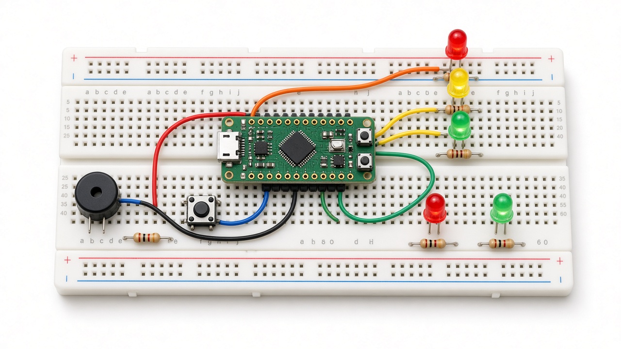
This Raspberry Pi Pico traffic light controller is a simple MicroPython project that copies a real pedestrian crossing. Cars normally get a green light. When someone presses the crossing button, the car lights go yellow and then red, the pedestrian light turns green, and a buzzer beeps to tell people it is safe to walk.
It is a small, beginner-friendly build with only five LEDs, one push button and one buzzer. You will learn digital outputs, button interrupts with debouncing and simple timing in MicroPython. No libraries are needed, so you can copy the code straight into Thonny and run it.
How the Traffic Light Controller Works
- Normal state: the car green LED and the pedestrian red LED are on. Cars always keep the green for at least 8 seconds.
- Button interrupt: the crossing button on GP15 uses the internal pull-up resistor. A press pulls the pin LOW and triggers an interrupt that sets a flag, with a 250 ms debounce time.
- Stopping the cars: after the minimum green time, the code switches car green to yellow (3 s), then to red, with a short all-red safety gap.
- Crossing time: the pedestrian green turns on with two long beeps and a slow tick. In the last 4 seconds it blinks and the buzzer ticks faster as a warning.
- Back to normal: the pedestrian light turns red, and after another all-red gap the cars get green again. Button presses made during the crossing are ignored.
Components Required
- Raspberry Pi Pico (or Pico W) – 1
- 5 mm LEDs: 2 red, 1 yellow, 2 green – 5 in total
- 220 Ω resistors – 5
- Push button (tactile switch) – 1
- Active buzzer (5 V or 3.3 V type) – 1
- Breadboard and jumper wires
- Micro-USB cable
Wiring Table (Pin-to-Pin)
| Part | Pico pin | Physical pin | Notes |
|---|---|---|---|
| Car RED LED (via 220 Ω) | GP10 | 14 | Resistor in series, LED cathode to GND |
| Car YELLOW LED (via 220 Ω) | GP11 | 15 | Resistor in series, LED cathode to GND |
| Car GREEN LED (via 220 Ω) | GP12 | 16 | Resistor in series, LED cathode to GND |
| Walk RED LED (via 220 Ω) | GP13 | 17 | Resistor in series, LED cathode to GND |
| Walk GREEN LED (via 220 Ω) | GP14 | 19 | Resistor in series, LED cathode to GND |
| Push button | GP15 | 20 | Other leg to GND, no external resistor needed |
| Active buzzer (+) | GP16 | 21 | Buzzer (–) to GND |
| All grounds | GND | 18 or 23 | Join everything on the breadboard GND rail |
Connection Diagram
The drawing below shows the exact pins and parts from the wiring table. Build the circuit with it and double-check each LED’s direction before powering on.
MicroPython Code
Flash the latest MicroPython firmware on the Pico, open Thonny, paste the code below and save it on the Pico as main.py so it runs automatically on power-up. The code is fully commented and was syntax-checked with Python 3.
"""
Raspberry Pi Pico Traffic Light Controller with Pedestrian Crossing Button
MicroPython - save this file on the Pico as main.py

Wiring (GP numbers as printed on the Pico):
  Car RED LED     -> GP10 -> 220 ohm -> LED -> GND
  Car YELLOW LED  -> GP11 -> 220 ohm -> LED -> GND
  Car GREEN LED   -> GP12 -> 220 ohm -> LED -> GND
  Walk RED LED    -> GP13 -> 220 ohm -> LED -> GND
  Walk GREEN LED  -> GP14 -> 220 ohm -> LED -> GND
  Crossing button -> GP15 and GND (internal pull-up is used)
  Active buzzer   -> GP16 (+) and GND (-)
"""

from machine import Pin
import time

# ---------- Pin setup ----------
car_red = Pin(10, Pin.OUT)
car_yellow = Pin(11, Pin.OUT)
car_green = Pin(12, Pin.OUT)
walk_red = Pin(13, Pin.OUT)
walk_green = Pin(14, Pin.OUT)
buzzer = Pin(16, Pin.OUT)
# Button connects GP15 to GND when pressed, so enable the internal pull-up
button = Pin(15, Pin.IN, Pin.PULL_UP)

# ---------- Timings (seconds) ----------
CAR_GREEN_MIN = 8      # minimum time cars keep the green light
CAR_YELLOW = 3         # yellow warning time
WALK_TIME = 8          # time pedestrians can cross
BLINK_TIME = 4         # walk-green blinking time before it ends
ALL_RED = 1            # safety gap with every light red

# Flag set by the button interrupt
walk_requested = False
last_press = 0


def button_irq(pin):
    """Runs when the button is pressed. Remembers the request (with debounce)."""
    global walk_requested, last_press
    now = time.ticks_ms()
    if time.ticks_diff(now, last_press) > 250:   # ignore bounce within 250 ms
        walk_requested = True
        last_press = now


# Trigger on the falling edge (button pressed pulls the pin LOW)
button.irq(trigger=Pin.IRQ_FALLING, handler=button_irq)


def beep(times, on_ms=100, off_ms=100):
    """Short beeps from the buzzer."""
    for _ in range(times):
        buzzer.value(1)
        time.sleep_ms(on_ms)
        buzzer.value(0)
        time.sleep_ms(off_ms)


def set_cars(red, yellow, green):
    """Set the three car lights in one call."""
    car_red.value(red)
    car_yellow.value(yellow)
    car_green.value(green)


def set_walk(red, green):
    """Set the two pedestrian lights in one call."""
    walk_red.value(red)
    walk_green.value(green)


def pedestrian_cycle():
    """Stop the cars and let pedestrians cross."""
    global walk_requested
    # 1. Cars: green -> yellow -> red
    set_cars(0, 1, 0)
    time.sleep(CAR_YELLOW)
    set_cars(1, 0, 0)
    time.sleep(ALL_RED)

    # 2. Pedestrians: red -> green, with a beep
    set_walk(0, 1)
    beep(2, 300, 150)

    # 3. Steady walk signal, with a slow tick from the buzzer
    for _ in range(WALK_TIME - BLINK_TIME):
        buzzer.value(1)
        time.sleep_ms(80)
        buzzer.value(0)
        time.sleep_ms(920)

    # 4. Blink green and beep faster to warn that time is running out
    for _ in range(BLINK_TIME * 2):
        walk_green.toggle()
        buzzer.value(1)
        time.sleep_ms(80)
        buzzer.value(0)
        time.sleep_ms(420)
    set_walk(1, 0)
    time.sleep(ALL_RED)

    # 5. Back to normal: cars get green again
    set_cars(0, 0, 1)
    walk_requested = False   # ignore presses made during the crossing


# ---------- Start-up test ----------
for led in (car_red, car_yellow, car_green, walk_red, walk_green):
    led.value(1)
beep(1, 200, 0)
time.sleep(1)
set_cars(0, 0, 1)
set_walk(1, 0)
walk_requested = False

# ---------- Main loop ----------
while True:
    # Cars have green; wait for a pedestrian request
    set_cars(0, 0, 1)
    set_walk(1, 0)
    time.sleep(CAR_GREEN_MIN)           # cars always get a minimum green time
    while not walk_requested:           # then wait until someone presses the button
        time.sleep_ms(50)
    pedestrian_cycle()
Code Explained
Pin(15, Pin.IN, Pin.PULL_UP)reads the button without an external resistor. The pin is HIGH normally and LOW when pressed.button.irq(...)callsbutton_irq()on the falling edge. The handler only sets a flag, which keeps the interrupt short and safe.time.ticks_diff()is used for debouncing, so a bouncing switch does not register many presses.set_cars()andset_walk()set several LEDs in one call, which makes the sequence inpedestrian_cycle()easy to read and change.- Change
CAR_GREEN_MIN,CAR_YELLOW,WALK_TIMEandBLINK_TIMEat the top of the file to adjust the timings.
Troubleshooting
| Problem | Fix |
|---|---|
| An LED never lights | Check its direction. The long leg (anode) must face the resistor and GPIO pin, and the short leg must go to GND. |
| Button does nothing | Make sure one leg goes to GP15 and the opposite leg to GND. Tactile buttons have two pairs of legs, so use legs on opposite sides. |
| Pedestrian cycle starts twice | Increase the 250 ms debounce value in button_irq(). |
| Buzzer is silent or only clicks | You may have a passive buzzer. Use an active buzzer, or drive a passive one with PWM. |
| Code does not run on power-up | The file must be saved on the Pico itself with the exact name main.py. |
Ideas to Extend This Project
- Add a 4-digit display or an OLED to show a countdown while pedestrians cross.
- Add an LDR so the LEDs dim at night.
- Use a second button on the other side of the road, wired in parallel to GP15.
- Make a four-way junction by adding more LED sets on free GPIO pins.
FAQ
Can I use a Pico W? Yes. The pins are the same, so the wiring and code stay unchanged.
Do I need resistors for the LEDs? Yes. A 220 Ω resistor limits the current to a safe value for both the LED and the Pico pin.
Can I write this in C++? Yes, with the Pico SDK or the Arduino-Pico core, using the same GPIO numbers. MicroPython is used here because it is the easiest way to start.