Raspberry Pi Pico Simon Says Memory Game with LEDs, Buzzer, OLED & High Score (MicroPython)

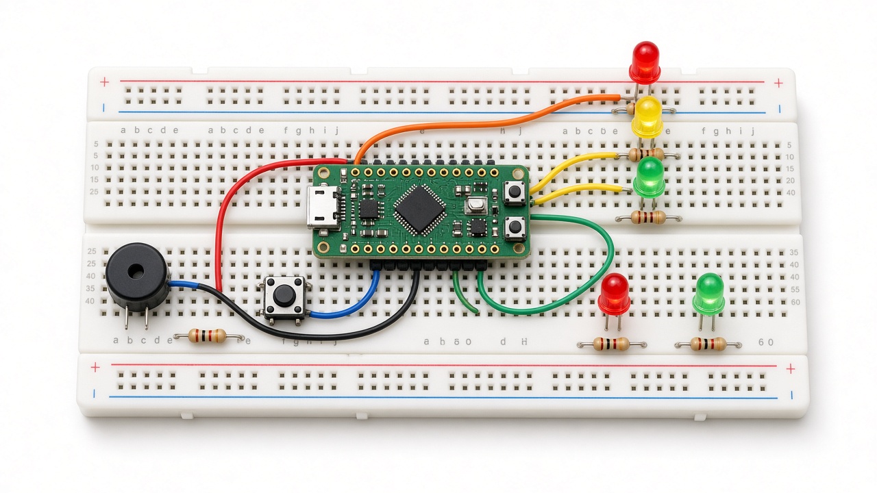
Raspberry Pi Pico Simon Says memory game on a breadboard with red, green, blue and yellow LEDs and buttons, a buzzer and an OLED showing level and best score

Build a Raspberry Pi Pico Simon Says memory game in MicroPython: four coloured LEDs and buttons, a musical buzzer, an OLED that shows the level, and a high score that stays saved in flash even after power-off.

  • DifficultyIntermediate
  • Build time2–3 hours
  • Board / MCURaspberry Pi Pico (RP2040)
  • Parts9 items
  • CodeMicroPython

Need it ready-made? Buy Ready Project

Simon Says is the classic memory game: the game flashes a pattern of coloured lights and notes, and you must repeat it in the same order. Every round adds one more step, and the pattern also plays a little faster, so it gets harder until you make a mistake. This Raspberry Pi Pico Simon Says game recreates it on a breadboard with four LEDs, four push buttons, a passive buzzer and a small OLED screen.

It is a fun weekend build for students and a great way to learn MicroPython inputs and outputs: digital outputs for the LEDs, button reading with debounce, PWM tones on a buzzer, I2C for the OLED display and saving a file to the Pico’s flash memory, so your best score is remembered even after you unplug it.

Raspberry Pi Pico Simon Says memory game on a breadboard with red, green, blue and yellow LEDs and buttons, a buzzer and an OLED showing level and best score

How It Works

  • Attract mode: after power-up the LEDs chase in a circle and the OLED shows the best score. Press any button to start. The exact moment you press is used as the random seed, so every game has a new pattern.
  • Computer’s turn: each round one random colour (0–3) is added to the sequence. The Pico plays the whole sequence, lighting each LED with its own note (C, E, G and high C). The step time starts at 480 ms and drops by 20 ms per level, down to 180 ms.
  • Your turn: you press the buttons in the same order. Each press lights the matching LED and plays its note while you hold it, just like the original game. Buttons are debounced in software (20 ms) and wait for release, so one press counts only once.
  • Time limit: you have 3 seconds for every press. If you are too slow or press the wrong colour, a falling game-over tune plays and the correct LED stays lit so you can see what you missed.
  • High score: your score is the number of rounds you completed. If it beats the record, the Pico writes it to hiscore.txt in flash and shows NEW RECORD on the OLED.

Components Required

  • Raspberry Pi Pico (or Pico W / Pico 2) – 1
  • 5 mm LEDs: red, green, blue and yellow – 1 each
  • 220 Ω resistors (for the LEDs) – 4
  • 12 mm tactile push buttons (coloured caps if available) – 4
  • Passive buzzer (not the self-oscillating active type) – 1
  • 100 Ω resistor (in series with the buzzer) – 1
  • 0.96 inch SSD1306 I2C OLED display, 128×64 – 1
  • Breadboard (full size) and jumper wires – 1 set
  • Micro-USB cable or 3×AA battery pack for power – 1

Wiring Table

Part / pinPico pinNotes
OLED VCC3V3(OUT) – pin 363.3 V supply for the display
OLED GNDGND – pin 38Common ground
OLED SDAGP0 – pin 1I2C0 data
OLED SCLGP1 – pin 2I2C0 clock
Red LED (via 220 Ω)GP2 – pin 4LED cathode to GND
Green LED (via 220 Ω)GP3 – pin 5LED cathode to GND
Blue LED (via 220 Ω)GP4 – pin 6LED cathode to GND
Yellow LED (via 220 Ω)GP5 – pin 7LED cathode to GND
Red buttonGP6 – pin 9Other leg to GND, internal pull-up
Green buttonGP7 – pin 10Other leg to GND
Blue buttonGP8 – pin 11Other leg to GND
Yellow buttonGP9 – pin 12Other leg to GND
Passive buzzer + (via 100 Ω)GP15 – pin 20Buzzer – to GND; PWM tone output

Connection Diagram

The illustration above shows a typical breadboard layout and is a layout guide only. Follow the pin-accurate drawing below, which matches the wiring table and the code.

Raspberry Pi Pico Simon Says Game – Pin-Accurate Wiring Raspberry Pi Pico GP0 (pin 1) OLED SDA GP1 (pin 2) OLED SCL GP2 (pin 4) 220 Ω → RED LED anode, cathode → GND GP3 (pin 5) 220 Ω → GREEN LED anode, cathode → GND GP4 (pin 6) 220 Ω → BLUE LED anode, cathode → GND GP5 (pin 7) 220 Ω → YELLOW LED anode, cathode → GND GP6 (pin 9) RED button → GND (internal pull-up) GP7 (pin 10) GREEN button → GND GP8 (pin 11) BLUE button → GND GP9 (pin 12) YELLOW button → GND GP15 (pin 20) 100 Ω → passive buzzer (+), buzzer (–) → GND 3V3 / GND OLED VCC to 3V3 (pin 36), all GNDs to common rail LED long leg (anode) goes to the resistor. Buttons need no external resistors: the code enables the internal pull-ups. Use a PASSIVE buzzer so the four notes sound different. Power from micro-USB or 3×AA (4.5 V) into VSYS (pin 39).
Pin-accurate connection diagram for the Raspberry Pi Pico Simon Says game.

Code

Flash the latest MicroPython UF2 for your board (hold BOOTSEL while plugging in the Pico and drop the file on the RPI-RP2 drive). In Thonny, open Tools → Manage packages, search for ssd1306 and install it (or copy the ssd1306.py driver from the micropython-lib repository to the Pico). Then save the code below to the Pico as main.py so the game starts automatically on power-up.

# Raspberry Pi Pico Simon Says Memory Game
# 4 LEDs + 4 buttons + passive buzzer + SSD1306 OLED, high score kept in flash
# Arduino Project Hub - ardiunoprojecthub.online
# Needs ssd1306.py on the Pico (Thonny: Tools > Manage packages > "ssd1306")

from machine import Pin, PWM, I2C
import time, urandom
import ssd1306

# ---------- pin map (matches the wiring table) ----------
LED_PINS = (2, 3, 4, 5)        # red, green, blue, yellow LEDs (220 ohm to GND)
BTN_PINS = (6, 7, 8, 9)        # matching buttons, other leg to GND
BUZZER_PIN = 15                # passive buzzer (+) through 100 ohm
TONES = (262, 330, 392, 523)   # C4, E4, G4, C5 - one note per colour
NAMES = ("RED", "GREEN", "BLUE", "YELLOW")

leds = [Pin(p, Pin.OUT, value=0) for p in LED_PINS]
btns = [Pin(p, Pin.IN, Pin.PULL_UP) for p in BTN_PINS]   # pressed = 0
buzzer = PWM(Pin(BUZZER_PIN))
buzzer.duty_u16(0)

i2c = I2C(0, sda=Pin(0), scl=Pin(1), freq=400000)
oled = ssd1306.SSD1306_I2C(128, 64, i2c)

SCORE_FILE = "hiscore.txt"
INPUT_TIMEOUT_MS = 3000        # time allowed for each button press


def load_best():
    try:
        with open(SCORE_FILE) as f:
            return int(f.read().strip() or 0)
    except (OSError, ValueError):
        return 0              # first run: file does not exist yet


def save_best(score):
    with open(SCORE_FILE, "w") as f:
        f.write(str(score))


def show(line1, line2="", line3=""):
    oled.fill(0)
    oled.text("SIMON SAYS", 24, 0)
    oled.hline(0, 10, 128, 1)
    oled.text(line1, 0, 20)
    oled.text(line2, 0, 34)
    oled.text(line3, 0, 48)
    oled.show()


def tone(freq, ms):
    if freq:
        buzzer.freq(freq)
        buzzer.duty_u16(20000)    # about 30 % duty = clear but not harsh
    time.sleep_ms(ms)
    buzzer.duty_u16(0)


def flash(i, ms):
    leds[i].value(1)
    tone(TONES[i], ms)
    leds[i].value(0)


def step_time(level):
    # sequence gets faster as the level goes up (min 180 ms per step)
    return max(180, 500 - level * 20)


def wait_press(timeout_ms):
    """Return button index 0-3, or -1 on timeout. Includes debounce."""
    start = time.ticks_ms()
    while time.ticks_diff(time.ticks_ms(), start) < timeout_ms:
        for i, b in enumerate(btns):
            if b.value() == 0:
                time.sleep_ms(20)              # debounce
                if b.value() == 0:
                    leds[i].value(1)
                    buzzer.freq(TONES[i])
                    buzzer.duty_u16(20000)
                    while b.value() == 0:      # wait for release
                        time.sleep_ms(5)
                    buzzer.duty_u16(0)
                    leds[i].value(0)
                    time.sleep_ms(30)
                    return i
        time.sleep_ms(2)
    return -1


def any_button():
    return any(b.value() == 0 for b in btns)


def game_over_sound():
    for f in (392, 330, 262, 196):
        tone(f, 180)
        time.sleep_ms(30)


def win_round_sound():
    tone(784, 60)
    time.sleep_ms(30)
    tone(1047, 90)


def attract_mode(best):
    """Chase the LEDs until any button is pressed."""
    show("Press any key", "to start", "Best: %d" % best)
    i = 0
    while not any_button():
        leds[i].value(1)
        time.sleep_ms(150)
        leds[i].value(0)
        i = (i + 1) % 4
    while any_button():           # wait for release so it is not counted
        time.sleep_ms(10)
    urandom.seed(time.ticks_us())  # human timing gives a random seed
    time.sleep_ms(400)


def play_game(best):
    sequence = []
    while True:
        sequence.append(urandom.getrandbits(2))   # add one random colour 0-3
        level = len(sequence)
        show("Level: %d" % level, "Watch...", "Best: %d" % best)
        time.sleep_ms(500)
        t = step_time(level)
        for c in sequence:                        # computer plays the pattern
            flash(c, t)
            time.sleep_ms(t // 2)

        show("Level: %d" % level, "Your turn!", "Best: %d" % best)
        for expected in sequence:                 # player repeats it
            pressed = wait_press(INPUT_TIMEOUT_MS)
            if pressed != expected:
                return level - 1, expected, pressed
        win_round_sound()
        time.sleep_ms(400)


best = load_best()
show("Ready!", "", "Best: %d" % best)
for i in range(4):
    flash(i, 120)

while True:
    attract_mode(best)
    score, expected, pressed = play_game(best)
    game_over_sound()
    leds[expected].value(1)      # show which colour was correct
    msg = "Too slow!" if pressed < 0 else "Wrong colour"
    if score > best:
        best = score
        save_best(best)
        show("NEW RECORD: %d" % score, msg, "Was " + NAMES[expected])
    else:
        show("Score: %d" % score, msg, "Was " + NAMES[expected])
    time.sleep_ms(2500)
    leds[expected].value(0)

How to Play

  • Press any button to start. Watch the LEDs and listen to the notes.
  • When the OLED says Your turn!, press the buttons in the same order.
  • Each correct round plays a short happy chirp and adds one more step.
  • To reset the high score, delete hiscore.txt from the Pico in Thonny’s file panel.

Troubleshooting

ProblemFix
ImportError: no module named ‘ssd1306’The OLED driver is not on the Pico. Install the ssd1306 package in Thonny or copy ssd1306.py to the Pico’s root folder.
OSError: [Errno 5] EIO at startThe OLED is not answering on I2C. Check SDA on GP0 and SCL on GP1, VCC on 3V3 and GND. Run print(i2c.scan()): you should see [60] (0x3C).
All four notes sound the same, or only a clickYou have an active buzzer. Replace it with a passive buzzer so the PWM frequency sets the pitch.
A button seems to press itselfThe button is wired to the wrong breadboard rows. Tactile buttons connect in pairs across the gap; use pins on opposite corners.
An LED never lightsThe LED is reversed. The long leg (anode) must go to the resistor and GPIO pin, the short leg to GND.
Game says Too slow! immediatelyA button is held or shorted to GND at start. Check that no button pin is touching the GND rail.
High score resets after unpluggingThe code must run from the Pico’s flash as main.py. Running it only from Thonny’s editor still saves, but check that hiscore.txt appears on the Pico.

Ideas to Extend

  • Add a two-player mode where players take turns adding one colour each.
  • Replace the LEDs with a WS2812B ring for brighter, bigger colours.
  • Add a difficulty switch that changes the start speed and time limit.

Raspberry Pi Pico Morse Code Trainer with Buzzer & Button (MicroPython)

Raspberry Pi Pico Morse code trainer on a breadboard with a push button key, active buzzer, red LED with 220 ohm resistor and a laptop showing Morse code for SOS

Build a Raspberry Pi Pico Morse code trainer that plays any text you type as dots and dashes on an LED and buzzer, and decodes the letters you tap on a push button key.

  • DifficultyEasy
  • Build time1–2 hours
  • Board / MCURaspberry Pi Pico (RP2040)
  • Parts8 items
  • CodeMicroPython

Need it ready-made? Buy Ready Project

This Raspberry Pi Pico Morse code trainer is a small, fun project that helps you learn Morse code by ear and by hand. In Send mode you type any word in the Thonny shell and the Pico plays it as dots and dashes on an LED and a buzzer. In Key mode you tap a push button like a telegraph key, and the Pico decodes your taps and prints the letters on your screen, so you can see straight away if your timing is right.

It needs only a Pico, one button, one LED, one buzzer and a resistor, so it is a great first MicroPython project. You will learn about digital input with pull-ups, debouncing, measuring press time with ticks_ms(), and reading text from the USB serial port without blocking the program.

Raspberry Pi Pico Morse code trainer on a breadboard with a push button key, active buzzer, red LED with 220 ohm resistor and a laptop showing Morse code for SOS

How It Works

  • Morse timing: everything is measured in units. A dot is 1 unit, a dash is 3 units, the gap inside a letter is 1 unit, between letters 3 units and between words 7 units. At 12 words per minute one unit is 100 ms.
  • Send mode: the Pico checks the USB serial port with select so the loop never freezes. When you press Enter, each character is looked up in a dictionary of letters, numbers and common punctuation, and the LED and buzzer are switched on for each dot or dash.
  • Key mode: the button is on GP15 with the internal pull-up, so it reads 0 when pressed. The code measures how long you hold it: under 250 ms is a dot, longer is a dash. The buzzer and LED sound while you press, like a real sidetone.
  • Decoding: when the button has been quiet for 600 ms the collected dots and dashes are looked up in a reverse dictionary and the letter is printed. After 1.5 seconds of silence a space is added between words. An unknown pattern prints a question mark.
  • Switching modes: hold the button for 3 seconds. Three short beeps mean Send mode, two beeps mean Key mode.

Components Required

  • Raspberry Pi Pico (or Pico W) with headers – 1
  • Tactile push button 12 mm (or a real Morse key) – 1
  • Active buzzer, 3.3V–5V type – 1
  • Red 5 mm LED – 1
  • 220 Ω resistor – 1
  • Half-size breadboard – 1
  • Male-to-male jumper wires – 6
  • Micro-USB data cable – 1

Wiring Table

Part / pinPico pinNotes
Push button leg 1GP15 (pin 20)Internal pull-up, no resistor needed
Push button leg 2GND (pin 18)Use legs on opposite sides of the button
220 Ω resistorGP14 (pin 19)Other end to the LED long leg (anode)
LED short leg (cathode)GND
Active buzzer +GP13 (pin 17)3.3 V buzzer; a 5 V buzzer needs a BC547 driver
Active buzzer –GND
Micro-USBComputerPower and serial (Thonny shell)

Connection Diagram

The illustration above shows the parts on the breadboard. It is a layout guide only, so follow the pin-accurate drawing below, which matches the wiring table.

Raspberry Pi Pico Morse Code Trainer – Pin-Accurate Wiring Raspberry Pi Pico GP15 (pin 20) Push button (Morse key) leg 1; leg 2 to GND (internal pull-up) GP14 (pin 19) 220 Ω resistor to LED long leg (anode); short leg to GND GP13 (pin 17) Active buzzer + ; buzzer – to GND GND (pin 18) Breadboard GND rail (button, LED and buzzer) USB Power and Thonny shell from the computer Use a 3.3 V active buzzer, or drive a 5 V one through a BC547 transistor.
Pin-accurate connection diagram for the Raspberry Pi Pico Morse code trainer.

Code

Flash the latest MicroPython UF2 for your board (hold BOOTSEL, plug in the Pico and drop the file on the RPI-RP2 drive). Open Thonny, select MicroPython (Raspberry Pi Pico), paste the code and save it to the Pico as main.py so it starts on power-up. No extra libraries are needed. On a Pico W change the onboard LED line to Pin("LED", Pin.OUT).

# Raspberry Pi Pico Morse Code Trainer (MicroPython)
# Arduino Project Hub - ardiunoprojecthub.online
#
# Two modes in one sketch:
#  1) SEND mode : type a word in the Thonny shell, the Pico plays it in
#                 Morse on the LED and buzzer.
#  2) KEY mode  : tap the push button like a Morse key. Short press = dot,
#                 long press = dash. The Pico decodes your letters and
#                 prints them in the shell.
# Hold the button for 3 seconds at any time to switch modes.
#
# Wiring:
#   GP15 -> push button -> GND   (internal pull-up, pressed = 0)
#   GP14 -> 220 ohm -> LED anode, LED cathode -> GND
#   GP13 -> active buzzer +, buzzer - -> GND  (3.3 V type, or via BC547)
#   Onboard LED (GP25) blinks once at boot.

from machine import Pin
import time
import sys
import select

BUTTON = Pin(15, Pin.IN, Pin.PULL_UP)
LED = Pin(14, Pin.OUT)
BUZZER = Pin(13, Pin.OUT)
BOARD_LED = Pin(25, Pin.OUT)   # use Pin("LED", Pin.OUT) on a Pico W

WPM = 12                       # words per minute for SEND mode
UNIT = 1200 // WPM             # length of one dot in milliseconds

MORSE = {
    'A': '.-', 'B': '-...', 'C': '-.-.', 'D': '-..', 'E': '.',
    'F': '..-.', 'G': '--.', 'H': '....', 'I': '..', 'J': '.---',
    'K': '-.-', 'L': '.-..', 'M': '--', 'N': '-.', 'O': '---',
    'P': '.--.', 'Q': '--.-', 'R': '.-.', 'S': '...', 'T': '-',
    'U': '..-', 'V': '...-', 'W': '.--', 'X': '-..-', 'Y': '-.--',
    'Z': '--..',
    '0': '-----', '1': '.----', '2': '..---', '3': '...--',
    '4': '....-', '5': '.....', '6': '-....', '7': '--...',
    '8': '---..', '9': '----.',
    '.': '.-.-.-', ',': '--..--', '?': '..--..', '/': '-..-.',
    '=': '-...-', '@': '.--.-.'
}
DECODE = {v: k for k, v in MORSE.items()}


def tone(on):
    LED.value(on)
    BUZZER.value(on)


def play_symbol(sym):
    tone(1)
    time.sleep_ms(UNIT if sym == '.' else UNIT * 3)
    tone(0)
    time.sleep_ms(UNIT)          # gap inside a letter


def play_text(text):
    print("Playing:", text)
    for ch in text.upper():
        if ch == ' ':
            time.sleep_ms(UNIT * 4)  # word gap = 7 units in total
            continue
        code = MORSE.get(ch)
        if code is None:
            continue                 # skip characters we cannot send
        print(ch, code)
        for sym in code:
            play_symbol(sym)
        time.sleep_ms(UNIT * 2)      # letter gap = 3 units in total
    print("Done.\n")


def read_line_nonblocking(buf):
    # Returns (line or None, buffer). Works in the Thonny / USB shell.
    while select.select([sys.stdin], [], [], 0)[0]:
        ch = sys.stdin.read(1)
        if ch in ('\n', '\r'):
            if buf:
                return buf, ''
        else:
            buf += ch
    return None, buf


def beep(times, ms=60):
    for _ in range(times):
        tone(1)
        time.sleep_ms(ms)
        tone(0)
        time.sleep_ms(ms)


# Timing for KEY mode (milliseconds). Tune these to your own speed.
DOT_MAX = 250        # press shorter than this = dot, longer = dash
LETTER_GAP = 600     # silence longer than this ends a letter
WORD_GAP = 1500      # silence longer than this adds a space
MODE_HOLD = 3000     # hold this long to switch modes

mode = 'KEY'
BOARD_LED.value(1)
time.sleep_ms(300)
BOARD_LED.value(0)
print("Pico Morse Code Trainer ready.")
print("KEY mode: tap the button. Hold 3 s to switch to SEND mode.")

symbols = ''
last_release = time.ticks_ms()
space_added = True
line_buf = ''

while True:
    # ----- button handling (both modes) -----
    if BUTTON.value() == 0:
        time.sleep_ms(15)                       # debounce
        if BUTTON.value() == 0:
            start = time.ticks_ms()
            if mode == 'KEY':
                tone(1)                         # sidetone while keying
            while BUTTON.value() == 0:
                if time.ticks_diff(time.ticks_ms(), start) > MODE_HOLD:
                    break
            held = time.ticks_diff(time.ticks_ms(), start)
            tone(0)
            if held > MODE_HOLD:
                mode = 'SEND' if mode == 'KEY' else 'KEY'
                symbols = ''
                beep(3 if mode == 'SEND' else 2)
                print("\n== Switched to", mode, "mode ==")
                if mode == 'SEND':
                    print("Type a word and press Enter.")
                while BUTTON.value() == 0:      # wait for release
                    time.sleep_ms(10)
            elif mode == 'KEY':
                symbols += '.' if held < DOT_MAX else '-'
                space_added = False
            last_release = time.ticks_ms()

    # ----- KEY mode: decode after gaps -----
    if mode == 'KEY':
        quiet = time.ticks_diff(time.ticks_ms(), last_release)
        if symbols and quiet > LETTER_GAP:
            letter = DECODE.get(symbols, '?')
            print(letter, end='')
            symbols = ''
        elif not symbols and not space_added and quiet > WORD_GAP:
            print(' ', end='')
            space_added = True

    # ----- SEND mode: read text from the shell -----
    else:
        line, line_buf = read_line_nonblocking(line_buf)
        if line:
            play_text(line.strip())
            print("Type another word and press Enter.")

    time.sleep_ms(5)

Testing

  • Run the script in Thonny. The onboard LED blinks once and the shell prints Pico Morse Code Trainer ready.
  • In Key mode tap three short, three long, three short. The shell should print SOS.
  • Hold the button for 3 seconds until you hear three beeps, then type HELLO in the shell and press Enter. The LED and buzzer play the word and each letter’s code is printed.
  • Change WPM to 5 for slow practice or 20 once you get faster.

Troubleshooting

ProblemFix
Every press prints E or T onlyEach press is being decoded as a full letter. Tap faster or raise LETTER_GAP to 800 ms.
Dashes are read as dotsRaise DOT_MAX to 300 ms, or hold dashes a little longer.
Button does nothingUse two legs on opposite sides of the button; legs on the same side are always connected. Check it goes to GP15 and GND.
Buzzer is silent but LED worksYou may have a passive buzzer, which needs a tone. Use an active buzzer, or check its + leg goes to GP13.
Typing in the shell does nothingYou are still in Key mode. Hold the button 3 seconds until three beeps, and click inside the Thonny shell before typing.
Nothing happens after unplugging from the computerSave the file to the Pico as main.py. Send mode needs the USB shell, but Key mode still sounds without it.

Ideas to Extend

  • Add a 0.96 inch I2C OLED to show the decoded text without a computer.
  • Add a quiz mode that plays a random letter and waits for you to key it back.
  • Use a Pico W to send your decoded messages to a phone over Wi-Fi.

Raspberry Pi Pico PID Line Follower Robot with 5-Channel IR Array, TB6612FNG & Obstacle Stop

Raspberry Pi Pico line follower robot with TB6612FNG driver, 5-channel IR sensor array, HC-SR04 sensor and OLED on a two-wheel chassis following a black line

Build a fast Raspberry Pi Pico line follower robot with PID steering, a 5-channel IR sensor array, a TB6612FNG motor driver, an ultrasonic obstacle stop and a live OLED status screen.

  • DifficultyAdvanced
  • Build time5–8 hours
  • Board / MCURaspberry Pi Pico (RP2040)
  • Parts13 items
  • CodeMicroPython

Need it ready-made? Buy Ready Project

This Raspberry Pi Pico line follower robot tracks a black tape line on a white floor using a 5-channel IR sensor array and smooth PID steering. A TB6612FNG driver runs the two gear motors, an HC-SR04 ultrasonic sensor stops the robot before it hits anything placed on the track, and a small OLED shows what each sensor sees, the obstacle distance, the battery voltage and the run time.

It is a complete robotics combination project: sensors, motor control, a control loop, power regulation and a user interface, all written in MicroPython. It is ideal for college mini projects, robotics competitions and anyone who wants to understand how PID control really works on a moving robot.

Raspberry Pi Pico line follower robot with TB6612FNG driver, 5-channel IR sensor array, HC-SR04 sensor and OLED on a two-wheel chassis following a black line

How It Works

  • Reading the line: each of the five IR sensors shines infrared light at the floor. White reflects it and black absorbs it, so each digital output tells the Pico whether that sensor is over the line. Most modules output LOW over black; set LINE_IS_LOW to match yours.
  • Position error: the sensors get weights of -2, -1, 0, +1 and +2 from left to right. The average weight of the sensors that see the line is the error: 0 means the line is centred, a negative value means it is to the left, a positive value means it is to the right.
  • PID steering: the correction is KP × error + KI × integral + KD × change in error. The correction is added to the left wheel speed and taken away from the right wheel speed, so the robot turns back towards the line smoothly instead of zig-zagging.
  • Motor driver: the TB6612FNG is a MOSFET driver, so it wastes far less voltage than an L298N. The Pico drives its PWM pins at 20 kHz (silent) and uses the IN pins for direction. Setting both IN pins high gives a short brake for quick stops.
  • Lost line and crossings: if no sensor sees the line, the robot spins towards the side where it last saw it until it finds it again. If all five see black (a cross or a finish mark), it keeps going straight.
  • Obstacle stop: the HC-SR04 is read every 60 ms. If something is closer than 15 cm the robot brakes and the buzzer sounds; it moves on as soon as the path is clear.
  • Power: two 18650 cells (7.4V) feed the motors directly through the TB6612 VM pin, and a buck converter makes a clean 5V for the Pico VSYS pin and the ultrasonic sensor. A 10 kΩ and 4.7 kΩ divider lets the Pico ADC measure the battery and warn when it is low.

Components Required

  • Raspberry Pi Pico or Pico W (with headers) – 1
  • 5-channel IR line sensor array (TCRT5000 type, digital outputs) – 1
  • TB6612FNG dual motor driver module – 1
  • N20 or TT gear motors (6V, 200 to 300 RPM) with wheels – 2
  • Caster ball wheel – 1
  • HC-SR04 ultrasonic sensor – 1
  • 0.96 inch SSD1306 I2C OLED (128×64) – 1
  • 2S 18650 battery holder with switch and two 18650 cells (7.4V) – 1
  • Mini buck converter (MP1584 or LM2596) set to 5V – 1
  • Active buzzer module (3.3V) – 1
  • Tactile push button – 1
  • Resistors: 1 kΩ and 2 kΩ (echo divider), 10 kΩ and 4.7 kΩ (battery monitor) – 1 each
  • Robot chassis plate (acrylic or 3 mm MDF), jumper wires, screws and 19 mm black electrical tape for the track

Wiring Table

Part / pinPico pinNotes
IR array S1, S2, S3, S4, S5GP2, GP3, GP4, GP5, GP6S1 is the far-left sensor; power the array from 3V3
IR array VCC / GND3V3 (pin 36) / GND3.3V supply keeps outputs safe for the Pico
TB6612 PWMA / AIN1 / AIN2GP16 / GP17 / GP18Left motor on A01 and A02
TB6612 PWMB / BIN1 / BIN2GP22 / GP20 / GP21Right motor on B01 and B02
TB6612 STBYGP19Set HIGH by the code to enable the driver
TB6612 VCC / VM / GND3V3 / battery + (7.4V) / GNDVM takes the motor supply
HC-SR04 VCC / GNDBuck 5V / GNDSensor needs 5V
HC-SR04 TRIGGP143.3V trigger is enough
HC-SR04 ECHOGP15 through 1 kΩ, 2 kΩ to GNDNever connect the 5V ECHO pin directly
OLED SDA / SCLGP0 / GP1I2C0, address 0x3C
Push buttonGP10 to GNDStart and stop
Active buzzer +GP11Negative pin to GND
Battery monitorGP26 (ADC0)Battery + to 10 kΩ to GP26, 4.7 kΩ GP26 to GND
Buck converter OUT 5VVSYS (pin 39)Set to 5.0V with a meter before connecting the Pico

Connection Diagram

The illustration near the top shows how the parts sit on the chassis. It is a layout guide only. Follow the pin-accurate drawing below, which matches the wiring table exactly.

Raspberry Pi Pico Line Follower Robot – Pin-Accurate Wiring Power (2S 7.4V) Battery + to switch, then TB6612 VM and buck converter IN+ Buck OUT 5V to Pico VSYS (pin 39) and HC-SR04 VCC All grounds common: battery -, buck -, Pico GND, TB6612 GND Battery + to 10 kΩ to GP26, 4.7 kΩ from GP26 to GND IR array (3.3V) VCC to Pico 3V3 (pin 36), GND to GND S1 GP2, S2 GP3, S3 GP4, S4 GP5, S5 GP6 (S1 = far left) TB6612FNG VCC to 3V3, STBY to GP19 PWMA GP16, AIN1 GP17, AIN2 GP18 (left motor on A01/A02) PWMB GP22, BIN1 GP20, BIN2 GP21 (right motor on B01/B02) HC-SR04 TRIG to GP14 ECHO to 1 kΩ to GP15, 2 kΩ from GP15 to GND OLED + UI OLED SDA GP0, SCL GP1, VCC 3V3, GND Button GP10 to GND (internal pull-up) Buzzer + to GP11, – to GND
Pin-accurate connection diagram for the Raspberry Pi Pico line follower robot.

Mechanical Setup

  • Mount the IR array at the front, 5 to 10 mm above the floor and centred between the wheels. Too high and it cannot tell black from white; too low and it scrapes.
  • Place the motors at the back and the caster ball at the front, or the other way round, so the robot sits level. The sensor array should be about 6 to 10 cm ahead of the wheel axle for stable steering.
  • Fix the HC-SR04 at the front facing forward, a little above the floor so it does not see the track itself.
  • Keep the battery low and near the wheels so the robot does not tip on sharp turns.
  • Make the track with 19 mm black electrical tape on a white chart sheet or a light floor, with curves no tighter than about 10 cm radius at first.

Code

Flash the latest MicroPython UF2 for your board (Pico or Pico W) and open Thonny. Install the ssd1306 package from Tools > Manage packages (the robot still runs without the OLED if it is missing). Save the code below on the Pico as main.py so it starts on power-up. On a Pico W change the on-board LED line to Pin("LED", Pin.OUT).

# Raspberry Pi Pico PID Line Follower Robot
# 5-channel IR array + TB6612FNG + HC-SR04 obstacle stop + SSD1306 OLED
# MicroPython for Raspberry Pi Pico / Pico W
# Arduino Project Hub - ardiunoprojecthub.online

from machine import Pin, PWM, I2C, ADC, time_pulse_us
import time

try:
    import ssd1306          # install "ssd1306" from Thonny > Tools > Manage packages
    HAVE_OLED = True
except ImportError:
    HAVE_OLED = False

# ---------------- Tuning (change these for your robot) ----------------
BASE_SPEED   = 45      # % duty on a straight line (35-60 is typical)
MAX_SPEED    = 85      # % duty limit for any wheel
KP           = 14.0    # proportional gain
KI           = 0.0     # integral gain (keep 0 at first)
KD           = 55.0    # derivative gain
STOP_CM      = 15      # stop if an obstacle is closer than this
LINE_IS_LOW  = True    # True if the sensor output goes LOW over the black line
LOW_BATT_V   = 6.6     # warn below this battery voltage (2S Li-ion)
DIVIDER      = (10000 + 4700) / 4700   # battery divider ratio (10k top, 4.7k bottom)

# ---------------- Pins ----------------
ir = [Pin(p, Pin.IN) for p in (2, 3, 4, 5, 6)]   # S1 (far left) .. S5 (far right)
WEIGHTS = (-2, -1, 0, 1, 2)

pwma = PWM(Pin(16)); ain1 = Pin(17, Pin.OUT); ain2 = Pin(18, Pin.OUT)   # left motor
stby = Pin(19, Pin.OUT)
bin1 = Pin(20, Pin.OUT); bin2 = Pin(21, Pin.OUT); pwmb = PWM(Pin(22))   # right motor
pwma.freq(20000); pwmb.freq(20000)

trig = Pin(14, Pin.OUT, value=0)
echo = Pin(15, Pin.IN)            # through 1k / 2k divider (5V -> 3.3V)
button = Pin(10, Pin.IN, Pin.PULL_UP)
buzzer = Pin(11, Pin.OUT, value=0)
led = Pin(25, Pin.OUT)            # on-board LED (Pico). On Pico W use Pin("LED")
batt = ADC(26)

oled = None
if HAVE_OLED:
    try:
        i2c = I2C(0, sda=Pin(0), scl=Pin(1), freq=400000)
        oled = ssd1306.SSD1306_I2C(128, 64, i2c)
    except Exception:
        oled = None

# ---------------- Helpers ----------------
def motor(pwm, in1, in2, speed):
    """speed -100..100 (%)."""
    speed = max(-100, min(100, speed))
    if speed >= 0:
        in1.value(1); in2.value(0)
    else:
        in1.value(0); in2.value(1)
    pwm.duty_u16(int(abs(speed) * 655.35))

def drive(left, right):
    motor(pwma, ain1, ain2, left)
    motor(pwmb, bin1, bin2, right)

def brake():
    ain1.value(1); ain2.value(1); bin1.value(1); bin2.value(1)
    pwma.duty_u16(65535); pwmb.duty_u16(65535)

def read_line():
    """Returns list of 1 (on line) / 0 (off line) for S1..S5."""
    return [(0 if p.value() else 1) if LINE_IS_LOW else p.value() for p in ir]

def distance_cm():
    trig.value(0); time.sleep_us(2)
    trig.value(1); time.sleep_us(10); trig.value(0)
    t = time_pulse_us(echo, 1, 25000)      # 25 ms timeout (~4 m)
    if t < 0:
        return 999
    return t / 58.0

def battery_v():
    return batt.read_u16() * 3.3 / 65535 * DIVIDER

def beep(ms=80, times=1):
    for _ in range(times):
        buzzer.value(1); time.sleep_ms(ms)
        buzzer.value(0); time.sleep_ms(ms)

def show(l1, l2="", l3="", l4=""):
    if not oled:
        return
    oled.fill(0)
    for i, t in enumerate((l1, l2, l3, l4)):
        oled.text(t, 0, i * 16)
    oled.show()

# ---------------- Main ----------------
stby.value(1)
brake()
running = False
last_error = 0.0
integral = 0.0
last_seen = 0            # -1 line was on the left, +1 on the right
lap_start = time.ticks_ms()
last_ui = 0
last_sonar = 0
dist = 999
beep(60, 2)

while True:
    now = time.ticks_ms()

    # Start / stop button (active LOW) with simple debounce
    if button.value() == 0:
        time.sleep_ms(30)
        if button.value() == 0:
            running = not running
            brake()
            integral = 0; last_error = 0
            lap_start = now
            beep(120 if running else 40)
            while button.value() == 0:
                time.sleep_ms(10)

    # Ultrasonic every 60 ms (keeps the PID loop fast)
    if time.ticks_diff(now, last_sonar) > 60:
        dist = distance_cm()
        last_sonar = now

    s = read_line()
    count = sum(s)

    if not running:
        brake()
        state = "READY - press btn"
    elif dist < STOP_CM:
        brake()
        state = "OBSTACLE!"
        buzzer.value(1)
    else:
        buzzer.value(0)
        if count == 0:
            # Line lost: spin toward the side where it was last seen
            state = "SEARCH"
            if last_seen < 0:
                drive(-35, 45)
            else:
                drive(45, -35)
        elif count == 5:
            # All black: finish mark or cross line - go straight
            state = "CROSS"
            drive(BASE_SPEED, BASE_SPEED)
        else:
            error = sum(w * v for w, v in zip(WEIGHTS, s)) / count
            if error < 0: last_seen = -1
            elif error > 0: last_seen = 1
            integral = max(-50, min(50, integral + error))
            derivative = error - last_error
            last_error = error
            corr = KP * error + KI * integral + KD * derivative
            left = max(-MAX_SPEED, min(MAX_SPEED, BASE_SPEED + corr))
            right = max(-MAX_SPEED, min(MAX_SPEED, BASE_SPEED - corr))
            drive(left, right)
            state = "RUN e=%+.1f" % error

    # Screen and LED update 4 times a second
    if time.ticks_diff(now, last_ui) > 250:
        last_ui = now
        v = battery_v()
        led.toggle()
        secs = time.ticks_diff(now, lap_start) // 1000 if running else 0
        show(state,
             "IR " + "".join("#" if x else "." for x in s),
             "Dist %3d cm" % min(dist, 999),
             "Bat %.1fV  %ds%s" % (v, secs, " LOW" if v < LOW_BATT_V else ""))

    time.sleep_ms(5)

Tuning the PID

  • Set KI and KD to 0 and BASE_SPEED to about 35.
  • Raise KP until the robot follows gentle curves but wobbles slightly on straights.
  • Raise KD step by step (20, 40, 60) until the wobble goes away and turns become smooth.
  • Only add a small KI (0.2 to 1) if the robot always drifts to one side of the line.
  • Increase BASE_SPEED slowly and re-tune KP and KD at each step.

Testing

  • Lift the robot off the floor, switch it on and check the OLED shows READY and the five sensor marks.
  • Move a strip of black tape under each sensor and confirm the matching # appears on the OLED. Adjust the blue trimmer on each sensor if needed.
  • Press the button: both wheels should spin forward. If one spins backwards, swap that motor’s two wires on the TB6612.
  • Put your hand 10 cm in front of the ultrasonic sensor: the wheels should stop and the buzzer should sound.
  • Place the robot on the track, press the button and tune the PID values.

Troubleshooting

ProblemFix
Robot turns away from the lineThe sensor order or the motors are swapped. Check S1 is on the left, or swap the left and right motor connections on the driver.
Sensors always read black or always whiteAdjust each sensor’s trimmer, change LINE_IS_LOW, and keep the array 5 to 10 mm above the floor. Strong sunlight can blind IR sensors.
Pico resets when the motors startThe motors are pulling the supply down. Use charged 18650 cells, keep the buck converter on its own wires from the battery, and add a 470 µF capacitor across VM and GND.
Robot wobbles on straight linesLower KP or raise KD, and reduce BASE_SPEED.
Robot overshoots sharp curvesLower BASE_SPEED or raise KP; move the sensor array further ahead of the wheels.
Stops for no reasonThe ultrasonic sensor sees the floor or the track edge. Point it slightly upward or reduce STOP_CM.
OLED stays blankCheck SDA on GP0 and SCL on GP1, and that the ssd1306 package is installed. Some modules use address 0x3D.

Ideas to Extend

  • Use a Pico W to send the live error and speed to a phone web page for wireless PID tuning.
  • Add wheel encoders and log lap times to the OLED for competition practice.
  • Use an 8-channel analog sensor array with the Pico ADC for even smoother steering.

Raspberry Pi Pico Digital Compass with QMC5883L & OLED (MicroPython)

Raspberry Pi Pico digital compass with QMC5883L GY-271 magnetometer, SSD1306 OLED, push button and buzzer on a breadboard

Build a Raspberry Pi Pico digital compass with a QMC5883L (GY-271) magnetometer and SSD1306 OLED, with a rotating compass rose, 16-point directions, one-button calibration and a north beep.

  • DifficultyIntermediate
  • Build time2–4 hours
  • Board / MCURaspberry Pi Pico (RP2040)
  • Parts7 items
  • CodeMicroPython

Need it ready-made? Buy Ready Project

This Raspberry Pi Pico digital compass shows which way you are facing on a small OLED screen. It reads the Earth’s magnetic field with a GY-271 module (QMC5883L chip) and displays the heading in degrees, a 16-point direction such as NE or SSW, and a compass rose whose N mark always turns to point at magnetic north.

It is a medium-level MicroPython build. You will learn how to share one I2C bus between two devices, read a magnetometer without any extra library, calibrate it to remove errors from nearby metal, and draw graphics on an SSD1306 OLED. A push button switches a north-finding beep on and off, and holding it starts a 20-second calibration that is saved on the Pico.

Raspberry Pi Pico digital compass with QMC5883L GY-271 magnetometer, SSD1306 OLED, push button and buzzer on a breadboard

How It Works

  • Magnetic sensing: the QMC5883L measures the magnetic field on the X, Y and Z axes. The code puts it in continuous mode at 200 Hz with the 8 gauss range and reads six bytes from registers 0x00 to 0x05.
  • Heading: with the board held flat, the heading is atan2(Y, X) converted to degrees. A small declination value (about -1 to +1 degree across India) is added to get closer to true north.
  • Calibration: screws, magnets and the breadboard itself shift the readings. During calibration you turn the compass in slow full circles while the code records the lowest and highest X and Y values. Their middle point is the offset and their spread gives a scale factor. These values are saved in calib.json, so you only calibrate once.
  • Smoothing: raw headings jitter a little. The code averages the heading as a direction vector, so the reading stays steady and does not jump when it crosses from 359 to 0 degrees.
  • Display: the left side of the OLED shows the heading and direction name. The right side draws a dotted compass ring, a fixed marker at the top for the direction the board faces, and a needle with an N that turns to magnetic north.
  • North beep: when the heading is within 5 degrees of north, the buzzer gives a short beep once per second. A short button press turns this on or off.

Components Required

  • Raspberry Pi Pico or Pico W – 1
  • GY-271 magnetometer module with QMC5883L chip – 1
  • 0.96 inch SSD1306 I2C OLED display, 128×64 – 1
  • Tactile push button (6×6 mm) – 1
  • Active buzzer, 3.3V or 5V type – 1
  • Breadboard and male-to-male jumper wires
  • Micro-USB cable, plus a power bank to use it outdoors

Wiring Table

Part / pinPico pinPhysical pinNotes
OLED VCC and GY-271 VCC3V3(OUT)36Both modules run on 3.3V
OLED GND and GY-271 GNDGND38Common ground
OLED SDA and GY-271 SDAGP4 (I2C0 SDA)6Shared I2C data line
OLED SCL and GY-271 SCLGP5 (I2C0 SCL)7Shared I2C clock line
GY-271 DRDYNot connected–Code polls the status register instead
Push button leg 1GP1520Internal pull-up, reads LOW when pressed
Push button leg 2GND23
Buzzer (+)GP1621Active buzzer
Buzzer (-)GND23
PowerMicro-USB–PC or power bank

Connection Diagram

The illustration above shows the parts and how they sit on the breadboard. It is a placement guide only, and its printed pin labels are not exact. The pin-accurate drawing below matches the wiring table, so follow it while you build.

Raspberry Pi Pico Digital Compass – Pin-Accurate Wiring Power Pico 3V3(OUT) pin 36: OLED VCC and GY-271 VCC Pico GND pin 38: OLED GND, GY-271 GND, button, buzzer (-) Power the Pico from micro-USB (PC or power bank) I2C bus (shared) GP4 (pin 6) = SDA: OLED SDA and GY-271 SDA GP5 (pin 7) = SCL: OLED SCL and GY-271 SCL OLED address 0x3C, QMC5883L address 0x0D GY-271 module DRDY pin not used, leave it unconnected Mount it flat, at least 10 cm from magnets, motors and steel Push button One leg to GP15 (pin 20), the other leg to GND Internal pull-up in code; short press = beep on/off, hold 2 s = calibrate Active buzzer Buzzer (+) to GP16 (pin 21), buzzer (-) to GND Beeps once per second while facing north
Pin-accurate connection diagram for the Raspberry Pi Pico digital compass.

MicroPython Code

Flash the latest MicroPython firmware on the Pico and open Thonny. Install the ssd1306 driver (Tools, Manage packages, search “ssd1306”) so that ssd1306.py is on the Pico. Then save the code below on the Pico as main.py. The magnetometer driver is built into the code, so no other library is needed. The code was syntax-checked with Python 3.

# Raspberry Pi Pico Digital Compass with QMC5883L (GY-271) and SSD1306 OLED
# MicroPython - save as main.py on the Pico. Also copy ssd1306.py to the Pico
# (Thonny: Tools > Manage packages > search "ssd1306" > install).
#
# Wiring: OLED and QMC5883L share I2C0 -> SDA = GP4, SCL = GP5, VCC = 3V3, GND = GND
#         Push button GP15 -> GND (internal pull-up), active buzzer GP16 -> GND
#
# Button: short press = north beep on/off, hold 2 s = 20 s calibration.

from machine import Pin, I2C
import math, time, json
import ssd1306

# ---------------- user settings ----------------
DECLINATION = -0.5     # magnetic declination in degrees (India is about -1 to +1)
NORTH_WINDOW = 5       # beep when heading is within +/- this many degrees of north
CAL_FILE = "calib.json"
CAL_TIME_MS = 20000    # rotate the compass slowly for this long during calibration

# ---------------- hardware ----------------
i2c = I2C(0, sda=Pin(4), scl=Pin(5), freq=400000)
oled = ssd1306.SSD1306_I2C(128, 64, i2c)
button = Pin(15, Pin.IN, Pin.PULL_UP)
buzzer = Pin(16, Pin.OUT, value=0)
led = Pin(25, Pin.OUT)   # on-board LED (on Pico W use Pin("LED", Pin.OUT))

QMC_ADDR = 0x0D

class QMC5883L:
    """Minimal driver for the QMC5883L 3-axis magnetometer."""
    def __init__(self, bus, addr=QMC_ADDR):
        self.i2c = bus
        self.addr = addr
        self.i2c.writeto_mem(addr, 0x0A, b"\x80")   # soft reset
        time.sleep_ms(10)
        self.i2c.writeto_mem(addr, 0x0B, b"\x01")   # SET/RESET period (datasheet value)
        # 0x1D = OSR 512, range 8 gauss, 200 Hz, continuous mode
        self.i2c.writeto_mem(addr, 0x09, b"\x1D")

    def ready(self):
        return self.i2c.readfrom_mem(self.addr, 0x06, 1)[0] & 0x01

    def read_raw(self):
        """Return raw (x, y, z) as signed 16-bit numbers."""
        t0 = time.ticks_ms()
        while not self.ready():
            if time.ticks_diff(time.ticks_ms(), t0) > 50:
                break
        d = self.i2c.readfrom_mem(self.addr, 0x00, 6)
        def s16(lo, hi):
            v = lo | (hi << 8)
            return v - 65536 if v > 32767 else v
        return s16(d[0], d[1]), s16(d[2], d[3]), s16(d[4], d[5])

# ---------------- calibration (hard-iron + simple soft-iron scale) ----------------
cal = {"xoff": 0, "yoff": 0, "xscale": 1.0, "yscale": 1.0}

def load_cal():
    global cal
    try:
        with open(CAL_FILE) as f:
            cal = json.load(f)
        print("Calibration loaded:", cal)
    except (OSError, ValueError):
        print("No calibration file - hold the button 2 s to calibrate")

def save_cal():
    with open(CAL_FILE, "w") as f:
        json.dump(cal, f)

def calibrate(mag):
    """Rotate the compass flat through several full circles to find min/max."""
    global cal
    xmin = ymin = 32767
    xmax = ymax = -32768
    t0 = time.ticks_ms()
    while time.ticks_diff(time.ticks_ms(), t0) < CAL_TIME_MS:
        x, y, _ = mag.read_raw()
        xmin, xmax = min(xmin, x), max(xmax, x)
        ymin, ymax = min(ymin, y), max(ymax, y)
        left = (CAL_TIME_MS - time.ticks_diff(time.ticks_ms(), t0)) // 1000
        oled.fill(0)
        oled.text("CALIBRATING", 20, 0)
        oled.text("Rotate slowly", 12, 16)
        oled.text("in full circles", 4, 28)
        oled.text("%2d s left" % left, 28, 48)
        oled.show()
        led.toggle()
        time.sleep_ms(50)
    led.off()
    xr, yr = (xmax - xmin) / 2, (ymax - ymin) / 2
    if xr < 50 or yr < 50:          # did not turn enough, keep old values
        show_message("Cal failed", "Turn more")
        return
    avg = (xr + yr) / 2
    cal = {"xoff": (xmax + xmin) / 2, "yoff": (ymax + ymin) / 2,
           "xscale": avg / xr, "yscale": avg / yr}
    save_cal()
    print("New calibration:", cal)
    show_message("Cal saved", "")

def show_message(line1, line2):
    oled.fill(0)
    oled.text(line1, 0, 24)
    oled.text(line2, 0, 40)
    oled.show()
    time.sleep(2)

# ---------------- heading maths ----------------
POINTS = ["N", "NNE", "NE", "ENE", "E", "ESE", "SE", "SSE",
          "S", "SSW", "SW", "WSW", "W", "WNW", "NW", "NNW"]

def heading_deg(x, y):
    xc = (x - cal["xoff"]) * cal["xscale"]
    yc = (y - cal["yoff"]) * cal["yscale"]
    h = math.degrees(math.atan2(yc, xc)) + DECLINATION
    return h % 360

def cardinal(h):
    return POINTS[int((h + 11.25) // 22.5) % 16]

# Smooth the heading with a vector average so 359 -> 0 does not jump
sx = sy = 0.0
def smooth(h, k=0.25):
    global sx, sy
    sx = sx * (1 - k) + math.cos(math.radians(h)) * k
    sy = sy * (1 - k) + math.sin(math.radians(h)) * k
    return math.degrees(math.atan2(sy, sx)) % 360

# ---------------- drawing ----------------
CX, CY, R = 96, 32, 28   # compass rose centre and radius (right side of screen)

def draw(h, beep_on):
    oled.fill(0)
    oled.text("%3d deg" % (round(h) % 360), 0, 4)
    oled.text(cardinal(h), 0, 22)
    oled.text("Beep:" + ("ON" if beep_on else "OFF"), 0, 54)
    # outer circle (drawn with points)
    for a in range(0, 360, 10):
        r = math.radians(a)
        oled.pixel(int(CX + R * math.sin(r)), int(CY - R * math.cos(r)), 1)
    # the "N" mark rotates so it always points to magnetic north
    n = math.radians(-h)
    nx, ny = CX + (R - 8) * math.sin(n), CY - (R - 8) * math.cos(n)
    oled.line(CX, CY, int(nx), int(ny), 1)
    oled.fill_rect(int(nx) - 4, int(ny) - 4, 9, 9, 0)
    oled.text("N", int(nx) - 3, int(ny) - 3)
    # fixed pointer at the top = direction the board is facing
    oled.fill_rect(CX - 1, CY - R - 3, 3, 5, 1)
    oled.show()

def beep(ms):
    buzzer.on(); time.sleep_ms(ms); buzzer.off()

# ---------------- main loop ----------------
def main():
    try:
        mag = QMC5883L(i2c)
    except OSError:
        show_message("QMC5883L", "not found!")
        print("I2C devices:", [hex(a) for a in i2c.scan()])
        return
    load_cal()
    beep_on = True
    last_beep = 0
    while True:
        # button: short press toggles beep, 2 s hold starts calibration
        if button.value() == 0:
            t0 = time.ticks_ms()
            while button.value() == 0 and time.ticks_diff(time.ticks_ms(), t0) < 2000:
                time.sleep_ms(10)
            if time.ticks_diff(time.ticks_ms(), t0) >= 2000:
                beep(100)
                calibrate(mag)
                while button.value() == 0:
                    time.sleep_ms(10)
            elif time.ticks_diff(time.ticks_ms(), t0) > 40:   # debounce
                beep_on = not beep_on
        x, y, _ = mag.read_raw()
        h = smooth(heading_deg(x, y))
        draw(h, beep_on)
        # short beep once per second while facing north
        off_north = min(h, 360 - h)
        if beep_on and off_north <= NORTH_WINDOW and time.ticks_diff(time.ticks_ms(), last_beep) > 1000:
            beep(40)
            last_beep = time.ticks_ms()
        time.sleep_ms(100)

main()

Calibrating and Testing

  • Run the code. The OLED shows the heading, the direction name and the compass rose.
  • Move away from laptops, speakers and steel tables. Hold the button for 2 seconds until the buzzer beeps and the screen says CALIBRATING.
  • Keep the compass flat and turn it slowly through two or three full circles during the 20 seconds. “Cal saved” means the values are stored in calib.json.
  • Check it against a phone compass app. Point the top of the board north and the reading should be close to 0 degrees, and the buzzer should beep.
  • Look up the magnetic declination for your city and set DECLINATION at the top of the code for the best accuracy.

Troubleshooting

ProblemFix
OLED shows “QMC5883L not found!”Check SDA on GP4 and SCL on GP5. The Shell prints the I2C addresses found. If you see 0x1E instead of 0x0D, your GY-271 has the older HMC5883L chip, which needs a different driver.
OLED stays blankMake sure ssd1306.py is saved on the Pico and the OLED address is 0x3C. Some 1.3 inch displays use the SH1106 chip and need the sh1106 driver.
Heading turns the wrong wayThe X and Y axes on some boards are mirrored. Change atan2(yc, xc) to atan2(-yc, xc) in heading_deg().
Reading is off by 20 degrees or moreCalibrate again, away from metal, and turn it through full circles. Keep the module at least 10 cm from the buzzer and any magnets.
Heading changes when you tilt itThis simple compass has no tilt compensation. Hold it flat, or add an MPU6050 accelerometer to correct for tilt.
“Cal failed” messageThe compass was not turned enough. Hold the button again and make slow, complete circles.

Ideas to Extend

  • Add an MPU6050 for a tilt-compensated compass that works at any angle.
  • Use a Pico W to send the heading to a web page, for a wind vane or an antenna pointer.
  • Add a NEO-6M GPS module and show the direction and distance back to a saved home point.

Raspberry Pi Pico Digital Stopwatch with TM1637 Display & Buzzer

Raspberry Pi Pico digital stopwatch with TM1637 display, start/stop and reset buttons and buzzer on a breadboard

Build a Raspberry Pi Pico digital stopwatch with a TM1637 4-digit display, start/stop and reset buttons and a buzzer. Wiring table, diagram and full MicroPython code.

  • DifficultyEasy
  • Build time1–2 hours
  • Board / MCURaspberry Pi Pico (RP2040)
  • Parts7 items
  • CodeMicroPython

Need it ready-made? Buy Ready Project

This Raspberry Pi Pico stopwatch is a simple beginner project that turns a Pico and a cheap 4-digit TM1637 display into a real digital stopwatch. One button starts and pauses the timer, a second button resets it, and a small buzzer gives a short beep on every press. It is ideal for timing experiments, sports practice, cooking or classroom quizzes.

It is written in MicroPython and includes a tiny TM1637 driver inside the code, so you do not need to copy any extra library files to the Pico.

Raspberry Pi Pico digital stopwatch with TM1637 display, start/stop and reset buttons and buzzer on a breadboard

How It Works

  • Timing: the Pico reads its millisecond counter with time.ticks_ms(). When you press START, it remembers the start moment; the elapsed time is the difference to now, plus any time collected before a pause. Using ticks_diff() keeps the maths correct even when the counter wraps around.
  • Display format: for the first minute the display shows seconds and hundredths (for example 07:42 means 7.42 seconds). After 60 seconds it switches to minutes and seconds, up to 99:59, where it stops and gives a long beep.
  • TM1637 module: the display uses a two-wire serial protocol (CLK and DIO) that looks similar to I2C but has no address. The driver sends three commands each time: write mode, the four digit patterns starting at address 0xC0, and display-on with brightness. Bit 7 of the second digit lights the colon.
  • Buttons: both buttons connect a GPIO pin to GND, with the Pico’s internal pull-up resistors enabled, so no external resistors are needed. A 20 ms check removes contact bounce. RESET works only while the stopwatch is paused, so a running time cannot be cleared by accident.
  • Buzzer: an active buzzer beeps when GP16 goes HIGH. Small 3V-5V active buzzers draw only about 20-30 mA, which a Pico pin can drive for short beeps; use a transistor for a louder buzzer.

Components Required

  • Raspberry Pi Pico (or Pico W / Pico 2) with headers – 1
  • TM1637 4-digit 7-segment display module with colon (0.56 inch) – 1
  • Tactile push buttons (12 mm or 6 mm) – 2
  • Active buzzer, 3.3V-5V – 1
  • Breadboard – 1
  • Male-to-male and male-to-female jumper wires
  • Micro-USB cable for power and programming – 1

Wiring Table

Component pinPico pinNotes
TM1637 VCC3V3(OUT), physical pin 36Module works at 3.3V, so logic levels match
TM1637 GNDGND, physical pin 38
TM1637 CLKGP2, physical pin 4Clock line
TM1637 DIOGP3, physical pin 5Data line
START/STOP button leg 1GP14, physical pin 19Internal pull-up enabled in code
START/STOP button leg 2GNDUse diagonal legs on a 4-pin button
RESET button leg 1GP15, physical pin 20Internal pull-up enabled in code
RESET button leg 2GND
Buzzer +GP16, physical pin 21Longer leg or marked +
Buzzer –GND, physical pin 23

Connection Diagram

The illustration above shows the general layout; its wire routes are only for orientation. The pin-accurate drawing below matches the wiring table exactly, so follow it while building.

Raspberry Pi Pico Stopwatch – Pin-Accurate Wiring Power Pico powered from USB (5V on VBUS) 3V3(OUT) pin 36 feeds the TM1637 module; all GNDs common TM1637 display VCC to 3V3(OUT) pin 36, GND to GND pin 38 CLK to GP2 (pin 4), DIO to GP3 (pin 5) START/STOP button One leg to GP14 (pin 19) Other leg to GND (internal pull-up enabled) RESET button One leg to GP15 (pin 20) Other leg to GND (internal pull-up enabled) Active buzzer Buzzer + to GP16 (pin 21) Buzzer – to GND (pin 23)
Pin-accurate connection diagram for the Raspberry Pi Pico stopwatch.

Code

Flash the latest MicroPython UF2 file to your Pico, open Thonny, select the MicroPython (Raspberry Pi Pico) interpreter, paste the code below and save it on the Pico as main.py. It will start automatically every time the Pico is powered.

"""
Raspberry Pi Pico Digital Stopwatch with TM1637 Display
MicroPython - save this file on the Pico as main.py

Wiring (GP numbers as printed on the Pico):
  TM1637 VCC  -> 3V3(OUT) (pin 36)
  TM1637 GND  -> GND
  TM1637 CLK  -> GP2
  TM1637 DIO  -> GP3
  START/STOP button -> GP14 and GND (internal pull-up used)
  RESET button      -> GP15 and GND (internal pull-up used)
  Active buzzer     -> GP16 (+) and GND (-)

Display format:
  below 60 s  ->  SS:cc  (seconds : hundredths)
  60 s or more -> MM:SS  (minutes : seconds), up to 99:59
"""

from machine import Pin
import time

# ---------------- Minimal TM1637 driver (no extra library needed) ----------------
# Segment patterns for digits 0-9 (bit 0 = segment a ... bit 6 = segment g)
DIGITS = [0x3F, 0x06, 0x5B, 0x4F, 0x66, 0x6D, 0x7D, 0x07, 0x7F, 0x6F]


class TM1637:
    def __init__(self, clk_pin, dio_pin, brightness=7):
        self.clk = Pin(clk_pin, Pin.OUT, value=1)
        self.dio = Pin(dio_pin, Pin.OUT, value=1)
        self.brightness = brightness & 0x07

    def _delay(self):
        time.sleep_us(5)  # TM1637 needs a few microseconds per clock edge

    def _start(self):
        self.dio(0)
        self._delay()
        self.clk(0)
        self._delay()

    def _stop(self):
        self.dio(0)
        self._delay()
        self.clk(1)
        self._delay()
        self.dio(1)

    def _write_byte(self, b):
        # Send 8 bits, least significant bit first
        for i in range(8):
            self.dio((b >> i) & 1)
            self._delay()
            self.clk(1)
            self._delay()
            self.clk(0)
            self._delay()
        # Ninth clock for the ACK bit (we ignore the ACK value)
        self.clk(0)
        self.dio(1)
        self._delay()
        self.clk(1)
        self._delay()
        self.clk(0)
        self._delay()

    def write(self, segments):
        # Command 1: write data, auto-increment address
        self._start()
        self._write_byte(0x40)
        self._stop()
        # Command 2: start address 0xC0, then the 4 digit bytes
        self._start()
        self._write_byte(0xC0)
        for seg in segments:
            self._write_byte(seg)
        self._stop()
        # Command 3: display on + brightness
        self._start()
        self._write_byte(0x88 | self.brightness)
        self._stop()

    def show_pair(self, left, right, colon=True):
        """Show two 2-digit numbers like 12:34."""
        segs = [DIGITS[left // 10], DIGITS[left % 10],
                DIGITS[right // 10], DIGITS[right % 10]]
        if colon:
            segs[1] |= 0x80  # bit 7 of digit 2 drives the colon
        self.write(segs)


# ---------------- Hardware setup ----------------
display = TM1637(clk_pin=2, dio_pin=3, brightness=5)
btn_start = Pin(14, Pin.IN, Pin.PULL_UP)   # pressed = 0
btn_reset = Pin(15, Pin.IN, Pin.PULL_UP)   # pressed = 0
buzzer = Pin(16, Pin.OUT, value=0)

MAX_MS = (99 * 60 + 59) * 1000 + 999       # stop counting at 99:59

# ---------------- Stopwatch state ----------------
running = False
start_ticks = 0      # ticks_ms() when the current run started
stored_ms = 0        # time collected before the last pause


def beep(ms=40):
    buzzer(1)
    time.sleep_ms(ms)
    buzzer(0)


def elapsed_ms():
    if running:
        return min(stored_ms + time.ticks_diff(time.ticks_ms(), start_ticks), MAX_MS)
    return stored_ms


def show_time(ms):
    total_s = ms // 1000
    if total_s < 60:
        # SS:cc  -> seconds and hundredths
        display.show_pair(total_s, (ms % 1000) // 10)
    else:
        # MM:SS  -> minutes and seconds
        display.show_pair(total_s // 60, total_s % 60)


def pressed(btn):
    """Return True once per press, with a simple 20 ms debounce."""
    if btn.value() == 0:
        time.sleep_ms(20)
        if btn.value() == 0:
            while btn.value() == 0:   # wait for release
                show_time(elapsed_ms())  # keep the display updating meanwhile
            return True
    return False


# ---------------- Main loop ----------------
show_time(0)
beep(80)  # power-on beep

while True:
    if pressed(btn_start):
        if running:
            # Pause: save the time collected so far
            stored_ms = elapsed_ms()
            running = False
        else:
            # Start or resume
            start_ticks = time.ticks_ms()
            running = True
        beep()

    if pressed(btn_reset) and not running:
        # Reset works only while paused, so a run cannot be cleared by mistake
        stored_ms = 0
        beep(120)

    ms = elapsed_ms()
    if running and ms >= MAX_MS:
        stored_ms = MAX_MS
        running = False
        beep(300)

    show_time(ms)
    time.sleep_ms(10)

Troubleshooting

ProblemFix
Display stays blankCheck that CLK is on GP2 and DIO on GP3 (swapping them gives a blank display). Make sure VCC is on 3V3(OUT), not on 3V3_EN.
Display shows random segmentsUse short jumper wires and a common ground. Increase the delay in _delay() from 5 to 10 microseconds.
Button press counts twiceRaise the debounce time in pressed() from 20 ms to 40 ms.
RESET does nothingPause the stopwatch first; reset is blocked while it is running on purpose.
No beepMake sure it is an active buzzer (it beeps on plain DC). A passive buzzer needs PWM instead.

Ideas to Extend

  • Add a third button to store lap times and show them on the serial console.
  • Add a countdown timer mode with the buzzer as an alarm.
  • Use a Pico W to send the final time to your phone over Wi-Fi.
  • Replace the buttons with IR sensors to make an automatic race timer.

Raspberry Pi Pico W Smart Greenhouse with Auto Watering, Fan & Web Dashboard

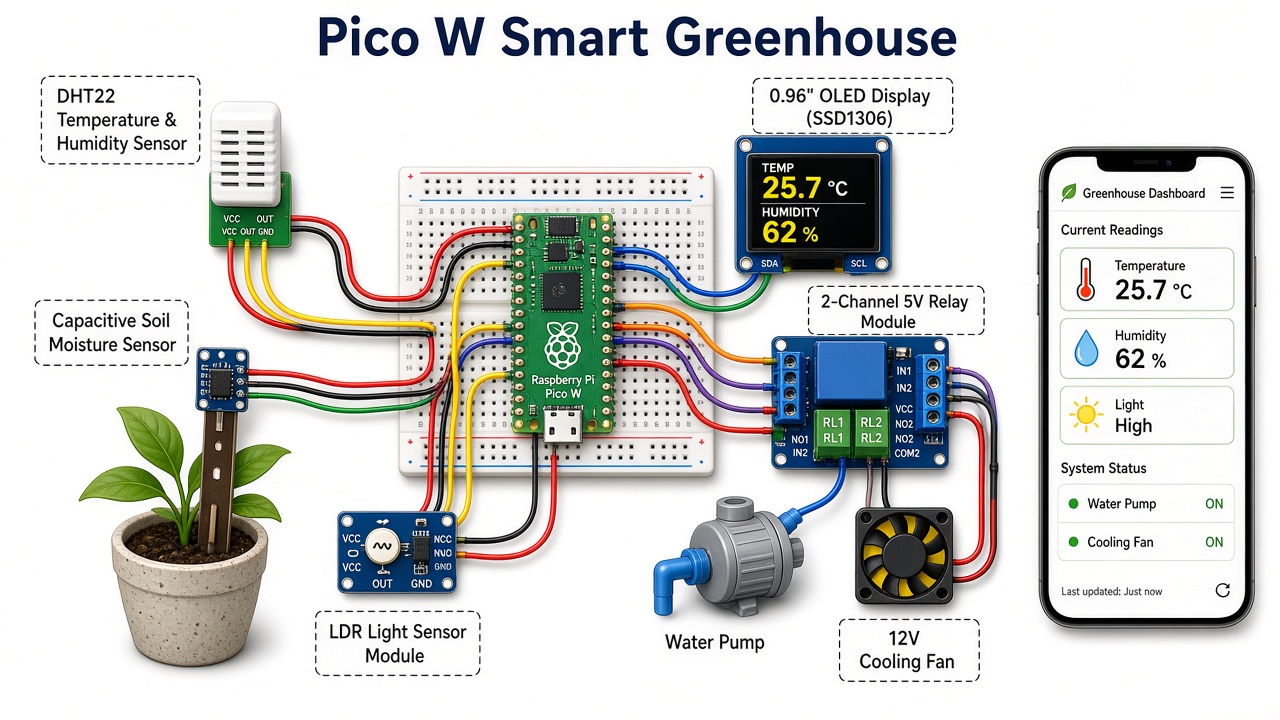
Raspberry Pi Pico W smart greenhouse wiring illustration with DHT22, soil moisture sensor, LDR, OLED, 2-channel relay, water pump, fan and phone dashboard

Build a Raspberry Pi Pico W smart greenhouse that reads temperature, humidity, soil moisture and light, waters plants and runs a fan automatically, and shows everything on an OLED and a Wi-Fi dashboard. MicroPython code, wiring and diagram.

  • DifficultyAdvanced
  • Build time5–8 hours
  • Board / MCURaspberry Pi Pico W
  • Parts11 items
  • CodeMicroPython

Need it ready-made? Buy Ready Project

This Raspberry Pi Pico W smart greenhouse watches the air temperature, humidity, soil moisture and light level around your plants and takes care of them on its own. When the soil gets dry it switches on a small water pump, and when the air gets too hot or too humid it runs a cooling fan.

Everything shows on a 0.96 inch OLED screen and on a live web dashboard that opens on any phone on your Wi-Fi. From the dashboard you can also switch the pump and fan by hand or return to automatic mode. It is a complete combination project that joins three sensors, a display, two relays and Wi-Fi, all programmed in MicroPython.

Raspberry Pi Pico W smart greenhouse wiring illustration with DHT22, soil moisture sensor, LDR, OLED, 2-channel relay, water pump, fan and phone dashboard

How It Works

  • Sensing: a DHT22 measures temperature and humidity, a capacitive soil moisture probe gives an analog voltage that the Pico reads on ADC0 (GP26), and an LDR module gives the light level on ADC1 (GP27). The raw soil reading is turned into a 0 to 100 % moisture value using two calibration numbers.
  • Pump control: the pump turns on when moisture falls below 35 % and turns off above 55 %. Two safety limits stop overwatering: the pump never runs longer than 30 seconds at a time and then waits 2 minutes so the water can soak in before the next reading.
  • Fan control: the fan starts above 32 °C or above 85 % humidity and stops below 29 °C. The gap between the on and off points (hysteresis) stops the relay from clicking on and off rapidly.
  • Display: every 2 seconds the OLED shows all four readings, the pump and fan state, and whether the system is in AUTO or MANUAL mode.
  • Web dashboard: the Pico W joins your Wi-Fi and runs a small web server with uasyncio. The page refreshes its six tiles every 3 seconds from /json. Pressing a Pump or Fan button switches to manual mode, and the Auto button hands control back to the sensors.
  • Offline safety: if Wi-Fi is not available, the greenhouse still waters and cools automatically. Only the dashboard is skipped.

Components Required

  • Raspberry Pi Pico W – 1
  • DHT22 (AM2302) temperature and humidity sensor – 1
  • 10 kΩ resistor (DHT22 pull-up, not needed on a 3-pin DHT22 module) – 1
  • Capacitive soil moisture sensor v1.2 – 1
  • LDR light sensor module (with analog AO pin) – 1
  • 0.96 inch SSD1306 I2C OLED (128×64) – 1
  • 2-channel 5 V relay module – 1
  • 5 V mini submersible water pump with tubing – 1
  • 12 V DC cooling fan – 1
  • 5 V supply for the pump and 12 V supply for the fan (or a 12 V pump on the same 12 V supply)
  • Breadboard, jumper wires, micro-USB cable and 5 V USB adapter for the Pico

Wiring Table

FromToNotes
DHT22 VCCPico 3V3 OUT (pin 36)
DHT22 DATAPico GP1510 kΩ pull-up to 3V3
DHT22 GNDPico GND
Soil sensor VCCPico 3V3 OUT
Soil sensor AOUTPico GP26 (ADC0)Analog moisture signal
Soil sensor GNDPico GND
LDR module VCCPico 3V3 OUT
LDR module AOPico GP27 (ADC1)Analog light signal
LDR module GNDPico GND
OLED VCCPico 3V3 OUT
OLED GNDPico GND
OLED SDAPico GP4I2C0 SDA
OLED SCLPico GP5I2C0 SCL, address 0x3C
Relay VCCPico VBUS (pin 40)5 V from USB
Relay GNDPico GND
Relay IN1Pico GP16Water pump channel
Relay IN2Pico GP17Cooling fan channel
Pump supply + to relay CH1 COM, CH1 NO to pump +Pump – to supply –Pump switched by relay 1
12 V + to relay CH2 COM, CH2 NO to fan +Fan – to 12 V –Fan switched by relay 2

Connection Diagram

The illustration above shows the overall layout. The pin-accurate drawing below matches the wiring table exactly, so follow it while building.

Pico W Smart Greenhouse – Pin-Accurate Wiring Raspberry Pi Pico W VBUS (pin 40): 5 V from USB to relay VCC 3V3 OUT (pin 36): DHT22, soil sensor, LDR, OLED VCC GND: common ground for all modules GP15: DHT22 DATA (10k pull-up to 3V3) GP26 / ADC0: soil sensor AOUT GP27 / ADC1: LDR module AO GP4 (SDA) / GP5 (SCL): OLED GP16: relay IN1 (pump), GP17: relay IN2 (fan) DHT22 VCC: 3V3 DATA: GP15 + 10k to 3V3 GND: GND Capacitive Soil Sensor v1.2 VCC: 3V3 AOUT: GP26 (ADC0) GND: GND LDR Light Module VCC: 3V3 AO: GP27 (ADC1) GND: GND SSD1306 OLED 0.96in VCC: 3V3 GND: GND SDA: GP4 SCL: GP5 2-Channel 5V Relay VCC: VBUS (5V), GND: GND IN1: GP16, IN2: GP17 CH1 COM/NO: in series with pump + supply CH2 COM/NO: in series with 12 V fan + supply Note: the pump and fan use their own supply through the relay contacts. Join only the grounds of the logic side.
Pin-accurate connection diagram for the Raspberry Pi Pico W smart greenhouse.

Setting Up MicroPython

  • Hold the BOOTSEL button, plug the Pico W into your computer and drag the latest Pico W MicroPython UF2 file onto the RPI-RP2 drive.
  • Open Thonny, choose the MicroPython (Raspberry Pi Pico) interpreter, and save the ssd1306.py driver from micropython-lib to the Pico.
  • Copy the code below into a new file, replace the Wi-Fi placeholders, and save it on the Pico as main.py so it runs on every power-up.

Code

# Raspberry Pi Pico W Smart Greenhouse Monitor & Controller (MicroPython)
# Sensors : DHT22 (temp/humidity), capacitive soil moisture, LDR light module
# Outputs : SSD1306 OLED, 2-channel relay (water pump + cooling fan)
# Web     : live dashboard + JSON at http://<pico-ip>/  and /json
# Needs   : ssd1306.py (from micropython-lib) copied to the Pico

import network, time, dht, json
import uasyncio as asyncio
from machine import Pin, ADC, I2C
from ssd1306 import SSD1306_I2C

# ---------- user settings ----------
WIFI_SSID = "YOUR_WIFI_SSID"          # placeholder, put your Wi-Fi name
WIFI_PASS = "YOUR_WIFI_PASSWORD"      # placeholder, put your Wi-Fi password

SOIL_DRY_RAW = 50000   # ADC reading with the probe in dry air (calibrate)
SOIL_WET_RAW = 20000   # ADC reading with the probe in a glass of water (calibrate)
SOIL_ON  = 35          # start pump below this moisture %
SOIL_OFF = 55          # stop pump above this moisture %
PUMP_MAX_S = 30        # never run the pump longer than this in one go
PUMP_REST_S = 120      # wait this long after a watering before the next one
FAN_ON_C  = 32.0       # start fan above this temperature
FAN_OFF_C = 29.0       # stop fan below this temperature
FAN_ON_RH = 85.0       # also run fan if humidity is above this
RELAY_ACTIVE_LOW = True  # most blue relay modules switch ON with a LOW input

# ---------- hardware ----------
dht_sensor = dht.DHT22(Pin(15))
soil_adc = ADC(26)                     # GP26 = ADC0
ldr_adc = ADC(27)                      # GP27 = ADC1
i2c = I2C(0, sda=Pin(4), scl=Pin(5), freq=400000)
oled = SSD1306_I2C(128, 64, i2c)
pump_pin = Pin(16, Pin.OUT)
fan_pin = Pin(17, Pin.OUT)
led = Pin("LED", Pin.OUT)              # on-board LED of the Pico W

state = {"temp": None, "hum": None, "soil": 0, "light": 0,
         "pump": False, "fan": False, "mode": "auto", "ip": "-"}
pump_started = 0
pump_stopped = -PUMP_REST_S * 1000

def set_relay(pin, on):
    # Drive a relay channel taking the module's active level into account
    pin.value(0 if (on == RELAY_ACTIVE_LOW) else 1)

def set_pump(on):
    global pump_started, pump_stopped
    if on and not state["pump"]:
        pump_started = time.ticks_ms()
    if not on and state["pump"]:
        pump_stopped = time.ticks_ms()
    state["pump"] = on
    set_relay(pump_pin, on)

def set_fan(on):
    state["fan"] = on
    set_relay(fan_pin, on)

set_pump(False)
set_fan(False)

def read_sensors():
    try:
        dht_sensor.measure()
        state["temp"] = dht_sensor.temperature()
        state["hum"] = dht_sensor.humidity()
    except OSError:
        pass  # keep last good value if one read fails
    raw = soil_adc.read_u16()
    pct = (SOIL_DRY_RAW - raw) * 100 // (SOIL_DRY_RAW - SOIL_WET_RAW)
    state["soil"] = max(0, min(100, pct))
    # LDR module output falls when light rises, so invert it to a 0-100 % light level
    state["light"] = 100 - ldr_adc.read_u16() * 100 // 65535

def auto_control():
    if state["mode"] != "auto":
        return
    now = time.ticks_ms()
    # Pump with hysteresis, maximum run time and rest time
    if state["pump"]:
        if state["soil"] >= SOIL_OFF or time.ticks_diff(now, pump_started) > PUMP_MAX_S * 1000:
            set_pump(False)
    elif state["soil"] < SOIL_ON and time.ticks_diff(now, pump_stopped) > PUMP_REST_S * 1000:
        set_pump(True)
    # Fan with hysteresis on temperature, plus high humidity
    t, h = state["temp"], state["hum"]
    if t is not None:
        if t > FAN_ON_C or (h is not None and h > FAN_ON_RH):
            set_fan(True)
        elif t < FAN_OFF_C and (h is None or h < FAN_ON_RH - 5):
            set_fan(False)

def draw_oled():
    oled.fill(0)
    oled.text("Smart Greenhouse", 0, 0)
    t = "--" if state["temp"] is None else "%.1f" % state["temp"]
    h = "--" if state["hum"] is None else "%.0f" % state["hum"]
    oled.text("Temp : %s C" % t, 0, 14)
    oled.text("Humid: %s %%" % h, 0, 24)
    oled.text("Soil : %d %%" % state["soil"], 0, 34)
    oled.text("Light: %d %%" % state["light"], 0, 44)
    oled.text("P:%s F:%s %s" % ("ON " if state["pump"] else "OFF",
                                 "ON " if state["fan"] else "OFF",
                                 state["mode"].upper()), 0, 56)
    oled.show()

PAGE = """<!DOCTYPE html><html><head><meta name=viewport content="width=device-width,initial-scale=1">
<title>Pico W Greenhouse</title><style>body{font-family:Arial;background:#eef5ee;margin:0;padding:12px}
.g{display:grid;grid-template-columns:1fr 1fr;gap:10px}.c{background:#fff;border-radius:10px;padding:12px;text-align:center}
.v{font-size:26px;font-weight:bold;color:#2e7d32}a{display:inline-block;margin:4px;padding:8px 12px;background:#2e7d32;color:#fff;border-radius:6px;text-decoration:none}</style></head>
<body><h2>Pico W Smart Greenhouse</h2><div class=g>
<div class=c>Temperature<div class=v id=temp>-</div></div><div class=c>Humidity<div class=v id=hum>-</div></div>
<div class=c>Soil moisture<div class=v id=soil>-</div></div><div class=c>Light<div class=v id=light>-</div></div>
<div class=c>Pump<div class=v id=pump>-</div></div><div class=c>Fan<div class=v id=fan>-</div></div></div>
<p>Mode: <b id=mode>-</b></p>
<a href=# onclick="go('/auto')">Auto</a><a href=# onclick="go('/pump/on')">Pump ON</a><a href=# onclick="go('/pump/off')">Pump OFF</a>
<a href=# onclick="go('/fan/on')">Fan ON</a><a href=# onclick="go('/fan/off')">Fan OFF</a>
<script>function go(u){fetch(u).then(r);return false}
function r(){fetch('/json').then(x=>x.json()).then(d=>{temp.textContent=d.temp===null?'-':d.temp.toFixed(1)+' C';
hum.textContent=d.hum===null?'-':d.hum.toFixed(0)+' %';soil.textContent=d.soil+' %';light.textContent=d.light+' %';
pump.textContent=d.pump?'ON':'OFF';fan.textContent=d.fan?'ON':'OFF';mode.textContent=d.mode})}
r();setInterval(r,3000)</script></body></html>"""

async def handle(reader, writer):
    try:
        line = await reader.readline()
        path = line.decode().split(" ")[1] if line else "/"
        while await reader.readline() not in (b"\r\n", b""):
            pass  # skip request headers
        # Manual buttons switch the mode to manual so auto logic does not undo them
        if path == "/auto":
            state["mode"] = "auto"
        elif path in ("/pump/on", "/pump/off", "/fan/on", "/fan/off"):
            state["mode"] = "manual"
            on = path.endswith("/on")
            set_pump(on) if path.startswith("/pump") else set_fan(on)
        if path == "/":
            body, ctype = PAGE, "text/html"
        else:
            body, ctype = json.dumps(state), "application/json"
        writer.write("HTTP/1.0 200 OK\r\nContent-Type: %s\r\nConnection: close\r\n\r\n" % ctype)
        writer.write(body)
        await writer.drain()
    except Exception as e:
        print("HTTP error:", e)
    finally:
        writer.close()
        await writer.wait_closed()

def connect_wifi():
    wlan = network.WLAN(network.STA_IF)
    wlan.active(True)
    wlan.connect(WIFI_SSID, WIFI_PASS)
    oled.fill(0); oled.text("Connecting Wi-Fi", 0, 24); oled.show()
    for _ in range(20):                # wait up to about 20 s
        if wlan.isconnected():
            break
        led.toggle()
        time.sleep(1)
    if wlan.isconnected():
        state["ip"] = wlan.ifconfig()[0]
        print("Dashboard: http://%s/" % state["ip"])
    else:
        print("Wi-Fi failed, running offline (auto control still works)")
    led.value(wlan.isconnected())

async def control_loop():
    while True:
        read_sensors()
        auto_control()
        draw_oled()
        await asyncio.sleep(2)         # DHT22 needs at least 2 s between reads

async def main():
    connect_wifi()
    asyncio.create_task(control_loop())
    if state["ip"] != "-":
        await asyncio.start_server(handle, "0.0.0.0", 80)
    while True:
        await asyncio.sleep(3600)

asyncio.run(main())

Calibrating the Soil Sensor

  • Run print(ADC(26).read_u16()) in the Thonny shell with the probe in dry air and note the number. Put it in SOIL_DRY_RAW.
  • Dip the probe in a glass of water up to the line and note the number again. Put it in SOIL_WET_RAW.
  • Push the probe into your plant’s soil and change SOIL_ON and SOIL_OFF to suit the plant. Succulents like it drier, leafy vegetables wetter.

Testing

  • Watch the Thonny shell: it prints the dashboard address, for example http://192.168.1.60/.
  • Breathe on the DHT22 to raise the humidity above 85 %; the fan relay should click on.
  • Pull the soil probe out into dry air; after a few seconds the pump should run for up to 30 seconds.
  • Open the dashboard on your phone, press Pump ON and Fan OFF, then press Auto to give control back.

Troubleshooting

ProblemFix
OLED stays blankCheck SDA on GP4 and SCL on GP5, and run i2c.scan(); it should show 60 (0x3C).
Temperature shows —Check the DHT22 data wire on GP15 and the 10 kΩ pull-up. Readings need at least 2 seconds between them.
Relays work the wrong way roundYour relay module is active HIGH. Set RELAY_ACTIVE_LOW = False.
Pico resets when the pump startsPower the pump from its own supply through the relay, not from the Pico, and keep the grounds of the logic side joined.
Dashboard does not openCheck the IP printed in Thonny and that your phone is on the same 2.4 GHz Wi-Fi.

Ideas to Extend

  • Add a grow light on a third relay that switches on when the light level stays low in the daytime.
  • Log readings every 10 minutes to a CSV file on the Pico’s flash or to a cloud sheet.
  • Add a water level float switch so the pump never runs with an empty tank.

Raspberry Pi Pico RGB Mood Lamp with WS2812B Ring & Rotary Encoder (MicroPython)

Raspberry Pi Pico RGB mood lamp wiring with WS2812B LED ring and KY-040 rotary encoder

Build a Raspberry Pi Pico RGB mood lamp with a WS2812B LED ring and a KY-040 rotary encoder: colour knob, 4 effects, brightness control and settings saved to flash. Wiring table, diagram and MicroPython code.

  • DifficultyIntermediate
  • Build time2–4 hours
  • Board / MCURaspberry Pi Pico (RP2040)
  • Parts8 items
  • CodeMicroPython

Need it ready-made? Buy Ready Project

This Raspberry Pi Pico RGB mood lamp uses a 12-LED WS2812B (NeoPixel) ring and a single KY-040 rotary encoder knob. Turn the knob to pick any colour, press it to switch between four lighting effects, and hold it to change brightness. The lamp saves your settings to the Pico’s flash memory, so it comes back exactly as you left it after a power cut.

It is a medium-level MicroPython project that teaches addressable LEDs, reading a rotary encoder with interrupts, short and long button presses, HSV colour mixing and saving data to flash.

Raspberry Pi Pico RGB mood lamp wiring with WS2812B LED ring and KY-040 rotary encoder

How the Pico Mood Lamp Works

  • Addressable LEDs: every LED on the WS2812B ring has its own tiny controller chip. The Pico sends a stream of colour data on one wire (GP16), and each LED takes its own 24-bit colour and passes the rest along. MicroPython’s built-in neopixel module handles the exact timing using the Pico’s PIO hardware.
  • Rotary encoder: the KY-040 gives two square waves (CLK and DT) that are out of step. An interrupt on CLK checks DT to know if the knob turned clockwise or anticlockwise, so no click is missed even while an animation is running.
  • HSV colour: instead of mixing red, green and blue by hand, the code uses hue (0 to 359 degrees). Each click of the knob moves the hue by 10 degrees, smoothly walking through the whole rainbow.
  • Four modes: Solid colour, Rainbow (colours rotate around the ring), Breathing (slow fade in and out) and Candle (warm random flicker). In Solid and Breathing the knob changes colour; in Rainbow and Candle it changes speed.
  • Button: a short press selects the next mode and the ring blinks blue 1 to 4 times to show which mode you are in. A press longer than 1 second steps the brightness through 10, 25, 50, 75 and 100%.
  • Memory: three seconds after your last change, the mode, colour, speed and brightness are written to a small file called lamp.cfg. Waiting a few seconds avoids wearing out the flash with constant writes.

Components Required

  • Raspberry Pi Pico or Pico H (RP2040) – 1
  • WS2812B RGB LED ring, 12 LEDs (8, 16 or 24 also work) – 1
  • KY-040 rotary encoder module with push switch – 1
  • 330 ohm resistor (data line) – 1
  • 1000 uF 10 V (or higher) electrolytic capacitor – 1
  • 5 V 2 A USB power adapter and micro-USB cable – 1
  • Breadboard and jumper wires
  • Optional: frosted glass jar or 3D-printed diffuser for the lamp shade

Wiring Table

Part / PinRaspberry Pi Pico pinNotes
WS2812B ring 5V / VCCVBUS (pin 40)5 V straight from USB
WS2812B ring GNDGND (pin 38)Common ground
WS2812B ring DINGP16 (pin 21) through 330 ohmResistor close to the ring input
1000 uF capacitorAcross ring 5V and GNDLong leg (+) to 5V, stripe (-) to GND
KY-040 + (VCC)3V3 OUT (pin 36)Encoder runs at 3.3 V, safe for Pico inputs
KY-040 GNDGND (pin 38 or any GND)Common ground
KY-040 CLKGP14 (pin 19)Interrupt input
KY-040 DTGP15 (pin 20)Direction input
KY-040 SWGP13 (pin 17)Push switch, internal pull-up used

The Pico’s data signal is 3.3 V while the ring runs at 5 V. With a short data wire this works on almost every WS2812B ring. If you see random colours, add a 74AHCT125 level shifter between GP16 and DIN, or power the ring from about 4.5 V.

Connection Diagram

The illustration above shows the general breadboard layout. The pin-accurate drawing below matches the wiring table exactly, so follow this one when you connect the wires.

Raspberry Pi Pico RGB Mood Lamp – Pin-Accurate Wiring Raspberry Pi Pico VBUS (pin 40) WS2812B ring 5V (+ 1000 uF capacitor + to 5V) GND (pin 38) Ring GND, encoder GND, capacitor – GP16 (pin 21) 330 ohm resistor -> ring DIN 3V3 OUT (pin 36) KY-040 encoder + (VCC) GP14 (pin 19) KY-040 CLK GP15 (pin 20) KY-040 DT GP13 (pin 17) KY-040 SW (push switch) Power the Pico from a 5 V 2 A USB adapter. Keep the ring data wire short (under 20 cm). Place the 1000 uF capacitor across the ring 5V and GND pads, minus leg to GND.
Pin-accurate connection diagram for the Raspberry Pi Pico RGB mood lamp.

MicroPython Code

Flash the latest MicroPython UF2 for the Raspberry Pi Pico, open Thonny, and save the code below to the Pico as main.py so it runs on every power-up. No extra libraries are needed, because neopixel is built into MicroPython for the RP2040.

# Raspberry Pi Pico RGB Mood Lamp
# WS2812B 12-LED ring + KY-040 rotary encoder (MicroPython)
#
# Controls:
#   Turn knob        : change colour (Solid mode) or speed (animated modes)
#   Short press      : next mode  (Solid -> Rainbow -> Breathing -> Candle)
#   Long press (1 s) : change brightness (25% -> 50% -> 75% -> 100% -> 10%)
# Settings are saved to flash, so the lamp remembers them after power-off.

import machine, neopixel, time, random

# ---------- Pin setup ----------
NUM_LEDS = 12                      # LEDs on the ring (change for 8/16/24 rings)
np = neopixel.NeoPixel(machine.Pin(16), NUM_LEDS)   # GP16 -> ring DIN (via 330R)

clk = machine.Pin(14, machine.Pin.IN, machine.Pin.PULL_UP)  # encoder CLK
dt  = machine.Pin(15, machine.Pin.IN, machine.Pin.PULL_UP)  # encoder DT
sw  = machine.Pin(13, machine.Pin.IN, machine.Pin.PULL_UP)  # encoder push switch

MODES = ["Solid", "Rainbow", "Breathing", "Candle"]
BRIGHT_STEPS = [0.10, 0.25, 0.50, 0.75, 1.00]
SETTINGS_FILE = "lamp.cfg"

# ---------- State ----------
mode = 0          # index into MODES
hue = 0           # 0..359, colour for Solid / Breathing
speed = 5         # 1..10 animation speed
bright = 2        # index into BRIGHT_STEPS
enc_count = 0     # steps counted by the interrupt
last_clk = clk.value()
dirty = False     # True when settings changed and need saving
last_change = time.ticks_ms()

# ---------- Rotary encoder interrupt ----------
def enc_isr(pin):
    global enc_count, last_clk
    c = clk.value()
    if c != last_clk and c == 0:          # count on the falling edge of CLK
        enc_count += 1 if dt.value() != c else -1
    last_clk = c

clk.irq(trigger=machine.Pin.IRQ_FALLING | machine.Pin.IRQ_RISING, handler=enc_isr)

# ---------- Helpers ----------
def hsv_to_rgb(h, s, v):
    """h 0..359, s and v 0..1 -> (r, g, b) 0..255"""
    h = h % 360
    c = v * s
    x = c * (1 - abs((h / 60) % 2 - 1))
    m = v - c
    if h < 60:    r, g, b = c, x, 0
    elif h < 120: r, g, b = x, c, 0
    elif h < 180: r, g, b = 0, c, x
    elif h < 240: r, g, b = 0, x, c
    elif h < 300: r, g, b = x, 0, c
    else:         r, g, b = c, 0, x
    return (int((r + m) * 255), int((g + m) * 255), int((b + m) * 255))

def fill(rgb):
    for i in range(NUM_LEDS):
        np[i] = rgb
    np.write()

def load_settings():
    global mode, hue, speed, bright
    try:
        with open(SETTINGS_FILE) as f:
            m, h, s, b = [int(x) for x in f.read().split(",")]
        mode, hue, speed, bright = m % len(MODES), h % 360, max(1, min(10, s)), b % len(BRIGHT_STEPS)
    except Exception:
        pass                                # first boot: keep defaults

def save_settings():
    with open(SETTINGS_FILE, "w") as f:
        f.write("{},{},{},{}".format(mode, hue, speed, bright))

def mark_changed():
    global dirty, last_change
    dirty = True
    last_change = time.ticks_ms()

# Short flash so the user can see which mode was selected (1..4 blinks)
def show_mode_blink():
    for _ in range(mode + 1):
        fill((0, 0, 60)); time.sleep_ms(120)
        fill((0, 0, 0));  time.sleep_ms(120)

# ---------- Main loop ----------
load_settings()
print("Mood lamp ready, mode:", MODES[mode])
phase = 0.0
btn_down_at = None

while True:
    # --- read the encoder steps collected by the interrupt ---
    state = machine.disable_irq()
    steps = enc_count
    enc_count = 0
    machine.enable_irq(state)
    if steps:
        if MODES[mode] in ("Solid", "Breathing"):
            hue = (hue + steps * 10) % 360          # 10 degrees per click
        else:
            speed = max(1, min(10, speed + steps))
        mark_changed()

    # --- button: short press = mode, long press = brightness ---
    if sw.value() == 0 and btn_down_at is None:
        btn_down_at = time.ticks_ms()
    elif sw.value() == 1 and btn_down_at is not None:
        held = time.ticks_diff(time.ticks_ms(), btn_down_at)
        btn_down_at = None
        if held > 1000:
            bright = (bright + 1) % len(BRIGHT_STEPS)
            print("Brightness:", int(BRIGHT_STEPS[bright] * 100), "%")
        elif held > 40:                              # ignore contact bounce
            mode = (mode + 1) % len(MODES)
            print("Mode:", MODES[mode])
            show_mode_blink()
        mark_changed()

    # --- draw the current effect ---
    v = BRIGHT_STEPS[bright]
    name = MODES[mode]
    if name == "Solid":
        fill(hsv_to_rgb(hue, 1, v))
    elif name == "Rainbow":
        phase = (phase + speed * 0.8) % 360
        for i in range(NUM_LEDS):
            np[i] = hsv_to_rgb(phase + i * 360 / NUM_LEDS, 1, v)
        np.write()
    elif name == "Breathing":
        phase = (phase + speed * 0.02) % 2
        level = phase if phase < 1 else 2 - phase    # triangle wave 0..1..0
        fill(hsv_to_rgb(hue, 1, v * (0.05 + 0.95 * level * level)))
    elif name == "Candle":
        for i in range(NUM_LEDS):
            flick = random.randint(60, 100) / 100
            np[i] = hsv_to_rgb(25 + random.randint(-5, 5), 1, v * flick)
        np.write()
        time.sleep_ms(110 - speed * 10)

    # --- save to flash 3 s after the last change (saves flash wear) ---
    if dirty and time.ticks_diff(time.ticks_ms(), last_change) > 3000:
        save_settings()
        dirty = False

    time.sleep_ms(20)

Setup and Testing

  • Connect the Pico to your computer, run main.py from Thonny and watch the shell. It prints the mode each time you press the knob.
  • Turn the knob slowly in Solid mode. The whole ring should step through red, yellow, green, cyan, blue and magenta.
  • Press the knob once and the ring should blink twice and start the rainbow animation. Turn the knob to make it faster or slower.
  • Hold the knob for more than 1 second to change the brightness.
  • Unplug the Pico, plug it back in after a few seconds and check that it comes back in the same mode and colour.

Power and Current

Each WS2812B LED draws up to about 60 mA at full white, so a 12-LED ring can draw around 0.7 A at 100% brightness. A 2 A USB adapter handles this easily, but a computer USB port may not, so test at 25 or 50% brightness when powering from a laptop. For a 24-LED ring use a separate 5 V supply for the LEDs and join its ground to the Pico ground.

Troubleshooting

ProblemFix
No LEDs light upCheck that the wire goes to DIN (input), not DOUT, and that VBUS really has 5 V. Confirm NUM_LEDS matches your ring.
First LED flickers or colours are randomAdd the 330 ohm resistor and the 1000 uF capacitor, shorten the data wire, or add a level shifter.
Knob changes colour in the wrong directionSwap the CLK and DT wires (GP14 and GP15).
Knob skips steps or jumps by twoTurn more slowly, or add 100 nF capacitors from CLK and DT to GND to clean up bounce.
Settings are not rememberedWait at least 3 seconds after the last change before unplugging; the file is saved after a short delay.
Pico resets when brightness goes to 100%The supply cannot give enough current. Use a 2 A adapter or lower the top brightness step.

Ideas to Extend

  • Swap the Pico for a Pico W and add a small web page to set the colour from your phone.
  • Add a microphone module for a music-reactive mode that pulses to sound.
  • Add an auto-off timer that fades the lamp out after 30 or 60 minutes for use as a night light.
  • Use a longer WS2812B strip behind a TV or desk for ambient backlighting.

Raspberry Pi Pico Traffic Light Controller with Pedestrian Crossing Button (MicroPython)

Raspberry Pi Pico traffic light controller on a breadboard with five LEDs, a pedestrian button and a buzzer

Build a pedestrian crossing traffic light with a Raspberry Pi Pico, five LEDs, a push button and a buzzer. Wiring table, diagram and fully commented MicroPython code included.

  • DifficultyEasy
  • Build time1–2 hours
  • Board / MCURaspberry Pi Pico (RP2040)
  • Parts7 items
  • CodeMicroPython

Need it ready-made? Buy Ready Project

Raspberry Pi Pico traffic light controller on a breadboard with five LEDs, a pedestrian button and a buzzer

This Raspberry Pi Pico traffic light controller is a simple MicroPython project that copies a real pedestrian crossing. Cars normally get a green light. When someone presses the crossing button, the car lights go yellow and then red, the pedestrian light turns green, and a buzzer beeps to tell people it is safe to walk.

It is a small, beginner-friendly build with only five LEDs, one push button and one buzzer. You will learn digital outputs, button interrupts with debouncing and simple timing in MicroPython. No libraries are needed, so you can copy the code straight into Thonny and run it.

How the Traffic Light Controller Works

  • Normal state: the car green LED and the pedestrian red LED are on. Cars always keep the green for at least 8 seconds.
  • Button interrupt: the crossing button on GP15 uses the internal pull-up resistor. A press pulls the pin LOW and triggers an interrupt that sets a flag, with a 250 ms debounce time.
  • Stopping the cars: after the minimum green time, the code switches car green to yellow (3 s), then to red, with a short all-red safety gap.
  • Crossing time: the pedestrian green turns on with two long beeps and a slow tick. In the last 4 seconds it blinks and the buzzer ticks faster as a warning.
  • Back to normal: the pedestrian light turns red, and after another all-red gap the cars get green again. Button presses made during the crossing are ignored.

Components Required

  • Raspberry Pi Pico (or Pico W) – 1
  • 5 mm LEDs: 2 red, 1 yellow, 2 green – 5 in total
  • 220 Ω resistors – 5
  • Push button (tactile switch) – 1
  • Active buzzer (5 V or 3.3 V type) – 1
  • Breadboard and jumper wires
  • Micro-USB cable

Wiring Table (Pin-to-Pin)

PartPico pinPhysical pinNotes
Car RED LED (via 220 Ω)GP1014Resistor in series, LED cathode to GND
Car YELLOW LED (via 220 Ω)GP1115Resistor in series, LED cathode to GND
Car GREEN LED (via 220 Ω)GP1216Resistor in series, LED cathode to GND
Walk RED LED (via 220 Ω)GP1317Resistor in series, LED cathode to GND
Walk GREEN LED (via 220 Ω)GP1419Resistor in series, LED cathode to GND
Push buttonGP1520Other leg to GND, no external resistor needed
Active buzzer (+)GP1621Buzzer (–) to GND
All groundsGND18 or 23Join everything on the breadboard GND rail

Connection Diagram

The drawing below shows the exact pins and parts from the wiring table. Build the circuit with it and double-check each LED’s direction before powering on.

Raspberry Pi Pico Traffic Light – Pin-Accurate Wiring Raspberry Pi Pico GP10 (pin 14) 220 Ω → Car RED LED → GND GP11 (pin 15) 220 Ω → Car YELLOW LED → GND GP12 (pin 16) 220 Ω → Car GREEN LED → GND GP13 (pin 17) 220 Ω → Walk RED LED → GND GP14 (pin 19) 220 Ω → Walk GREEN LED → GND GP15 (pin 20) Push button → GND (internal pull-up) GP16 (pin 21) Active buzzer (+); buzzer (–) → GND GND (pin 18 / 23) Common GND rail of the breadboard LED long leg (anode) faces the resistor; short leg goes to GND. Power: micro-USB 5 V (no external supply needed).
Pin-accurate connection diagram for the Raspberry Pi Pico traffic light controller.

MicroPython Code

Flash the latest MicroPython firmware on the Pico, open Thonny, paste the code below and save it on the Pico as main.py so it runs automatically on power-up. The code is fully commented and was syntax-checked with Python 3.

"""
Raspberry Pi Pico Traffic Light Controller with Pedestrian Crossing Button
MicroPython - save this file on the Pico as main.py

Wiring (GP numbers as printed on the Pico):
  Car RED LED     -> GP10 -> 220 ohm -> LED -> GND
  Car YELLOW LED  -> GP11 -> 220 ohm -> LED -> GND
  Car GREEN LED   -> GP12 -> 220 ohm -> LED -> GND
  Walk RED LED    -> GP13 -> 220 ohm -> LED -> GND
  Walk GREEN LED  -> GP14 -> 220 ohm -> LED -> GND
  Crossing button -> GP15 and GND (internal pull-up is used)
  Active buzzer   -> GP16 (+) and GND (-)
"""

from machine import Pin
import time

# ---------- Pin setup ----------
car_red = Pin(10, Pin.OUT)
car_yellow = Pin(11, Pin.OUT)
car_green = Pin(12, Pin.OUT)
walk_red = Pin(13, Pin.OUT)
walk_green = Pin(14, Pin.OUT)
buzzer = Pin(16, Pin.OUT)
# Button connects GP15 to GND when pressed, so enable the internal pull-up
button = Pin(15, Pin.IN, Pin.PULL_UP)

# ---------- Timings (seconds) ----------
CAR_GREEN_MIN = 8      # minimum time cars keep the green light
CAR_YELLOW = 3         # yellow warning time
WALK_TIME = 8          # time pedestrians can cross
BLINK_TIME = 4         # walk-green blinking time before it ends
ALL_RED = 1            # safety gap with every light red

# Flag set by the button interrupt
walk_requested = False
last_press = 0


def button_irq(pin):
    """Runs when the button is pressed. Remembers the request (with debounce)."""
    global walk_requested, last_press
    now = time.ticks_ms()
    if time.ticks_diff(now, last_press) > 250:   # ignore bounce within 250 ms
        walk_requested = True
        last_press = now


# Trigger on the falling edge (button pressed pulls the pin LOW)
button.irq(trigger=Pin.IRQ_FALLING, handler=button_irq)


def beep(times, on_ms=100, off_ms=100):
    """Short beeps from the buzzer."""
    for _ in range(times):
        buzzer.value(1)
        time.sleep_ms(on_ms)
        buzzer.value(0)
        time.sleep_ms(off_ms)


def set_cars(red, yellow, green):
    """Set the three car lights in one call."""
    car_red.value(red)
    car_yellow.value(yellow)
    car_green.value(green)


def set_walk(red, green):
    """Set the two pedestrian lights in one call."""
    walk_red.value(red)
    walk_green.value(green)


def pedestrian_cycle():
    """Stop the cars and let pedestrians cross."""
    global walk_requested
    # 1. Cars: green -> yellow -> red
    set_cars(0, 1, 0)
    time.sleep(CAR_YELLOW)
    set_cars(1, 0, 0)
    time.sleep(ALL_RED)

    # 2. Pedestrians: red -> green, with a beep
    set_walk(0, 1)
    beep(2, 300, 150)

    # 3. Steady walk signal, with a slow tick from the buzzer
    for _ in range(WALK_TIME - BLINK_TIME):
        buzzer.value(1)
        time.sleep_ms(80)
        buzzer.value(0)
        time.sleep_ms(920)

    # 4. Blink green and beep faster to warn that time is running out
    for _ in range(BLINK_TIME * 2):
        walk_green.toggle()
        buzzer.value(1)
        time.sleep_ms(80)
        buzzer.value(0)
        time.sleep_ms(420)
    set_walk(1, 0)
    time.sleep(ALL_RED)

    # 5. Back to normal: cars get green again
    set_cars(0, 0, 1)
    walk_requested = False   # ignore presses made during the crossing


# ---------- Start-up test ----------
for led in (car_red, car_yellow, car_green, walk_red, walk_green):
    led.value(1)
beep(1, 200, 0)
time.sleep(1)
set_cars(0, 0, 1)
set_walk(1, 0)
walk_requested = False

# ---------- Main loop ----------
while True:
    # Cars have green; wait for a pedestrian request
    set_cars(0, 0, 1)
    set_walk(1, 0)
    time.sleep(CAR_GREEN_MIN)           # cars always get a minimum green time
    while not walk_requested:           # then wait until someone presses the button
        time.sleep_ms(50)
    pedestrian_cycle()

Code Explained

  • Pin(15, Pin.IN, Pin.PULL_UP) reads the button without an external resistor. The pin is HIGH normally and LOW when pressed.
  • button.irq(...) calls button_irq() on the falling edge. The handler only sets a flag, which keeps the interrupt short and safe.
  • time.ticks_diff() is used for debouncing, so a bouncing switch does not register many presses.
  • set_cars() and set_walk() set several LEDs in one call, which makes the sequence in pedestrian_cycle() easy to read and change.
  • Change CAR_GREEN_MIN, CAR_YELLOW, WALK_TIME and BLINK_TIME at the top of the file to adjust the timings.

Troubleshooting

ProblemFix
An LED never lightsCheck its direction. The long leg (anode) must face the resistor and GPIO pin, and the short leg must go to GND.
Button does nothingMake sure one leg goes to GP15 and the opposite leg to GND. Tactile buttons have two pairs of legs, so use legs on opposite sides.
Pedestrian cycle starts twiceIncrease the 250 ms debounce value in button_irq().
Buzzer is silent or only clicksYou may have a passive buzzer. Use an active buzzer, or drive a passive one with PWM.
Code does not run on power-upThe file must be saved on the Pico itself with the exact name main.py.

Ideas to Extend This Project

  • Add a 4-digit display or an OLED to show a countdown while pedestrians cross.
  • Add an LDR so the LEDs dim at night.
  • Use a second button on the other side of the road, wired in parallel to GP15.
  • Make a four-way junction by adding more LED sets on free GPIO pins.

FAQ

Can I use a Pico W? Yes. The pins are the same, so the wiring and code stay unchanged.

Do I need resistors for the LEDs? Yes. A 220 Ω resistor limits the current to a safe value for both the LED and the Pico pin.

Can I write this in C++? Yes, with the Pico SDK or the Arduino-Pico core, using the same GPIO numbers. MicroPython is used here because it is the easiest way to start.

Raspberry Pi Pico Dual-Axis Solar Tracker with LDR Sensors, Servos & OLED (MicroPython)

Wiring diagram of a Raspberry Pi Pico dual-axis solar tracker with four LDR sensors, two servo motors, an SSD1306 OLED and a solar panel voltage divider

Build a Raspberry Pi Pico dual-axis solar tracker with four LDRs, two servos and an OLED. Includes MicroPython code, a wiring table and a connection diagram.

  • DifficultyAdvanced
  • Build time5–8 hours
  • Board / MCURaspberry Pi Pico (RP2040)
  • Parts12 items
  • CodeMicroPython

Need it ready-made? Buy Ready Project

This Raspberry Pi Pico dual-axis solar tracker turns a small solar panel toward the brightest light on both axes. Four LDR (light-dependent resistor) sensors sit on a plus-shaped divider. They are wired as two voltage dividers — left against right, and up against down — so the Pico only needs two analog pins to tell which way the sun has moved. Two SG90 servo motors then pan and tilt the panel, and a 0.96" SSD1306 OLED shows the raw ADC readings, the servo angles and the panel voltage.

It is a bigger combination build: a Pico (or Pico W), four LDRs, two servos, an I2C display and a simple resistor divider that measures the panel. The Pico has only three usable ADC channels, so pairing the LDRs is the right design — you get a true difference signal on each axis and still have GP28 free to watch the panel. There is no Wi-Fi in the basic program. If you later add a Pico W web page, put YOUR_WIFI_SSID and YOUR_WIFI_PASSWORD in the code and never type real credentials.

Use it as a desktop sun-follower, a science-fair demonstrator or the pointing head on a small 6 V hobby panel. It is not a storm-rated roof tracker and the plastic SG90 gears are not meant for a heavy framed module.

How the Pico Dual-Axis Solar Tracker Works

Each LDR drops in resistance as more light falls on it. Wire LDR LEFT from 3.3 V to the midpoint and LDR RIGHT from that midpoint to ground. When the left sensor is brighter its resistance falls, so the midpoint voltage rises toward 3.3 V. When the right sensor is brighter the midpoint falls toward 0 V. Equal light sits near 1.65 V. The vertical pair does the same for up and down.

The Pico reads those midpoints with its 12-bit ADC (MicroPython’s read_u16() scales the result to 0–65535). A centre value of about 32768 means the two sensors in that pair match. If the reading stays inside a dead-band, the code holds the servos still so the frame does not chatter. Outside the dead-band it steps the matching servo one degree at a time toward the brighter side.

  • Pan (azimuth): GP26 reads the left/right pair. GP14 sends a 50 Hz servo pulse to the base (pan) servo, which turns the whole tilt bracket.
  • Tilt (elevation): GP27 reads the up/down pair. GP15 drives the tilt servo that pitches the panel.
  • Panel voltage: the panel positive goes through 22 kΩ to GP28, then 10 kΩ to ground. The code reconstructs the real panel voltage so you can see it climb as the panel faces the lamp or the sun.
  • OLED: I2C0 on GP4 (SDA) and GP5 (SCL) shows H and V readings, pan and tilt angles, panel volts and AUTO or HOLD.
  • HOLD button (optional): tap GP16 to ground to freeze the servos, and tap again to resume tracking.

Power is split on purpose. The Pico, the OLED and the LDR dividers run from the Pico’s 3.3 V rail (the Pico itself is powered from USB). The two servos need a separate 5 V supply of about 2 A. A stalling SG90 can pull several hundred milliamps, and two of them will brown out a PC USB port and reset the Pico. Join the external 5 V negative to a Pico GND pin so the 3.3 V control pulses have a return path. Do not feed 5 V into the Pico’s 3V3 pin.

Components Required

  • Raspberry Pi Pico or Pico W, with MicroPython firmware – 1
  • SG90 (or MG90S) 5 V servo motors – 2
  • LDR sensors, 5 mm, typical dark resistance in the 100 kΩ–1 MΩ range – 4
  • 0.96" SSD1306 I2C OLED (128×64, 3.3 V, often address 0x3C) – 1
  • Small 6 V hobby solar panel (about 1 W; open-circuit a little over 6 V) – 1
  • Resistors: 22 kΩ (panel series) – 1, and 10 kΩ (panel lower leg) – 1
  • Optional 10 nF ceramic capacitors across each ADC node to ground – 3 (they quiet the readings)
  • Tactile push-button (optional AUTO/HOLD) – 1
  • External 5 V DC supply, 2 A, for the servos – 1
  • Pan-tilt bracket for two SG90 servos (ready-made, 3D-printed or built from light plywood/card)
  • A plus-shaped shade between the four LDRs (card, foam-board or 3D-printed) so each sensor sees a different quarter of the sky
  • Jumper wires, a breadboard for the electronics, and a USB cable for the Pico

Wiring Table (Pin-to-Pin)

PartPart Pin / NodePico PinNotes
OLED SSD1306VCC3V33.3 V only
OLED SSD1306GNDGNDCommon ground
OLED SSD1306SDAGP4I2C0 data (physical pin 6)
OLED SSD1306SCLGP5I2C0 clock (physical pin 7)
LDR LEFTone lead3V3Top of the horizontal divider
LDR LEFTother leadGP26 and LDR RIGHTMidpoint of the left/right pair (ADC0, pin 31)
LDR RIGHTother leadGNDBottom of the horizontal divider
LDR UPone lead3V3Top of the vertical divider
LDR UPother leadGP27 and LDR DOWNMidpoint of the up/down pair (ADC1, pin 32)
LDR DOWNother leadGNDBottom of the vertical divider
Solar panel+22 kΩ, then GP28Series resistor into ADC2 (pin 34)
Divider10 kΩ from GP28GNDLower leg. 22 kΩ + 10 kΩ keeps a 6 V panel under 3.3 V at the ADC
Solar panel−GNDJoin to Pico ground
Pan servoSignal (usually orange)GP1450 Hz PWM (physical pin 19)
Pan servoVCC (usually red)External +5 VDo not take this from Pico 3V3
Pan servoGND (usually brown)Pico GND and supply GNDCommon ground is required
Tilt servoSignal (usually orange)GP1550 Hz PWM (physical pin 20)
Tilt servoVCC (usually red)External +5 VShare the 2 A servo supply
Tilt servoGND (usually brown)Pico GND and supply GNDCommon ground
HOLD buttonone contactGP16Internal pull-up; physical pin 21
HOLD buttonother contactGNDTap to freeze or resume
PicoVBUS / USBUSB computer or 5 VPowers only the Pico and the 3.3 V rail

The Pico’s ADC pins are GP26, GP27 and GP28 only. GP29 is not a free analog input — it is used on the board to measure VSYS — so do not plan a fourth independent LDR channel without an analog multiplexer. Pairing the sensors, as in the table, is the intended design.

Never let the voltage on GP28 go above 3.3 V. With 22 kΩ and 10 kΩ the ADC sees about 31 percent of the panel voltage, so the panel can rise to about 10.5 V before the pin is out of range. That covers a typical 6 V hobby panel, including its higher open-circuit voltage in full sun. A 12 V panel needs a taller top resistor (for example 33 kΩ + 10 kΩ) and a matching change to R_TOP_OHM in the code.

Connection Diagram

The diagram below matches the wiring table. The generated illustration is the featured image for this post; the labelled drawing under it is the pin-accurate version to build from.

Wiring diagram of a Raspberry Pi Pico dual-axis solar tracker with four LDR sensors, two servo motors, an SSD1306 OLED and a solar panel voltage divider
Raspberry Pi Pico dual-axis solar tracker wiring: four LDRs as two pairs, two SG90 servos, SSD1306 OLED and a 22 kΩ / 10 kΩ panel divider.
Raspberry Pi Pico Dual-Axis Solar Tracker – Wiring Horizontal LDR pair LEFT and RIGHT in series LDR L LDR R midpoint → GP26 (ADC0) 3.3 V GND Vertical LDR pair UP and DOWN in series LDR U LDR D midpoint → GP27 (ADC1) 3.3 V GND 6 V solar panel sense small 6 V panel panel + → 22 kΩ → GP28 → 10 kΩ → GND panel − → Pico GND max about 10.5 V before the ADC exceeds 3.3 V RP2040 dual core Raspberry Pi Pico or Pico W USB (Pico power) 3V3 GP26 GP27 GP28 GND GP4 GP5 GP14 GP15 GP16 ADC0 / ADC1 / ADC2 AUTO 5.82 V OLED 0.96" SSD1306 I2C VCC GND SCL SDA Pan servo (SG90) signal → GP14 VCC → external +5 V GND → common GND turns the tilt bracket (azimuth) Tilt servo (SG90) signal → GP15 VCC → external +5 V GND → common GND pitches the panel (elevation) External 5 V / 2 A supply servo VCC only — join its GND to Pico GND Hold button (optional) GP16 to GND, internal pull-up H mid → GP26 V mid → GP27 divider → GP28 LDR tops and OLED VCC → 3V3 GP4 → SDA GP5 → SCL GP14 → pan GP15 → tilt GP16 → button Common GND (Pico, LDRs, OLED, panel −, servos, 5 V supply) Power: Pico and OLED from USB 5 V (on-board regulator makes 3.3 V). Four LDRs and the OLED run at 3.3 V. Both servos use a separate 5 V / 2 A supply with a shared ground. ADC: GP26 horizontal pair, GP27 vertical pair, GP28 panel divider (22 kΩ + 10 kΩ). I2C OLED on GP4 (SDA) and GP5 (SCL). Optional HOLD button on GP16.
Pin-accurate connection diagram for the Pico dual-axis solar tracker: LDR pairs on GP26 and GP27, panel divider on GP28, OLED on GP4/GP5, pan servo on GP14, tilt servo on GP15, optional HOLD button on GP16.

MicroPython Code for the Raspberry Pi Pico

Flash official MicroPython onto the Pico with Thonny (Interpreter: MicroPython (Raspberry Pi Pico)). Install the SSD1306 driver from Thonny’s package manager (search for ssd1306) or copy ssd1306.py onto the board. Save the program below as main.py if you want it to start whenever the Pico gets power, or as tracker.py and run it from Thonny while you tune the dead-band.

"""
Raspberry Pi Pico Dual-Axis Solar Tracker
MicroPython, SSD1306 OLED, two SG90 servos, four LDRs, panel voltage sense

Hardware (GP numbers as printed on the Pico silk):
  Horizontal LDR pair midpoint -> GP26 (ADC0)
  Vertical   LDR pair midpoint -> GP27 (ADC1)
  Panel divider midpoint       -> GP28 (ADC2)
  Pan servo signal             -> GP14
  Tilt servo signal            -> GP15
  OLED SDA                     -> GP4   (I2C0)
  OLED SCL                     -> GP5   (I2C0)
  Optional AUTO/HOLD button    -> GP16 to GND (internal pull-up)
  OLED VCC                     -> 3V3
  LDR pair tops                -> 3V3
  All grounds together, including the external 5 V servo supply

Copy ssd1306.py onto the Pico (Thonny: Tools > Manage packages > ssd1306)
or from micropython-lib. Save this file as main.py to run on power-up.
"""

from machine import Pin, ADC, PWM, I2C
from ssd1306 import SSD1306_I2C
import time

# --- pins ---
ADC_H_PIN = 26          # left / right LDR pair
ADC_V_PIN = 27          # up / down LDR pair
ADC_PANEL_PIN = 28      # solar panel voltage divider
PAN_PIN = 14
TILT_PIN = 15
SDA_PIN = 4
SCL_PIN = 5
BTN_PIN = 16            # tap to freeze or unfreeze the servos

# --- tracker tuning ---
# ADC is 16-bit via read_u16() (0 to 65535). Equal light is near 32768.
DEADBAND = 2500         # ignore small differences so the frame does not jitter
STEP_DEG = 1            # degrees to move each loop while light is off-centre
LOOP_S = 0.04           # seconds between moves
INVERT_PAN = False      # True if the pan servo runs away from the light
INVERT_TILT = False     # True if the tilt servo runs away from the light
PAN_MIN, PAN_MAX = 10, 170
TILT_MIN, TILT_MAX = 20, 160   # keep the panel from slamming the bracket

# SG90 pulse width. Many horns want 0.5 ms (0 deg) to 2.5 ms (180 deg).
PULSE_MIN_MS = 0.5
PULSE_MAX_MS = 2.5
PWM_HZ = 50             # 20 ms period

# Panel divider: 22 kOhm from panel+ to ADC, 10 kOhm from ADC to GND.
# Vpanel = Vadc * (RTOP + RBOT) / RBOT
R_TOP_OHM = 22000
R_BOT_OHM = 10000
ADC_VREF = 3.3

OLED_W, OLED_H = 128, 64
OLED_ADDR = 0x3C        # try 0x3D if the screen stays blank

adc_h = ADC(ADC_H_PIN)
adc_v = ADC(ADC_V_PIN)
adc_panel = ADC(ADC_PANEL_PIN)

pan_pwm = PWM(Pin(PAN_PIN))
tilt_pwm = PWM(Pin(TILT_PIN))
pan_pwm.freq(PWM_HZ)
tilt_pwm.freq(PWM_HZ)

button = Pin(BTN_PIN, Pin.IN, Pin.PULL_UP)

i2c = I2C(0, sda=Pin(SDA_PIN), scl=Pin(SCL_PIN), freq=400000)
oled = None
try:
    oled = SSD1306_I2C(OLED_W, OLED_H, i2c, addr=OLED_ADDR)
except Exception as exc:
    print("OLED not found:", exc)
    print("I2C scan:", i2c.scan())


def angle_to_duty(angle):
    """Convert 0-180 degrees to a 16-bit PWM duty for a 50 Hz servo."""
    if angle < 0:
        angle = 0
    if angle > 180:
        angle = 180
    pulse_ms = PULSE_MIN_MS + (angle / 180.0) * (PULSE_MAX_MS - PULSE_MIN_MS)
    period_ms = 1000.0 / PWM_HZ
    return int(65535 * pulse_ms / period_ms)


def set_servos(pan_deg, tilt_deg):
    pan_pwm.duty_u16(angle_to_duty(pan_deg))
    tilt_pwm.duty_u16(angle_to_duty(tilt_deg))


def read_panel_volts():
    raw = adc_panel.read_u16()
    v_adc = (raw / 65535.0) * ADC_VREF
    return v_adc * (R_TOP_OHM + R_BOT_OHM) / R_BOT_OHM


def clamp(value, lo, hi):
    if value < lo:
        return lo
    if value > hi:
        return hi
    return value


def draw(pan_deg, tilt_deg, raw_h, raw_v, volts, tracking):
    if oled is None:
        return
    oled.fill(0)
    oled.text("Pico Solar Track", 0, 0)
    oled.hline(0, 10, OLED_W, 1)
    mode = "AUTO" if tracking else "HOLD"
    oled.text("H:{:5d} P:{:3d}".format(raw_h, int(pan_deg)), 0, 16)
    oled.text("V:{:5d} T:{:3d}".format(raw_v, int(tilt_deg)), 0, 28)
    oled.text("Panel:{:5.2f} V".format(volts), 0, 40)
    oled.text("Mode: {}".format(mode), 0, 52)
    oled.show()


def button_pressed():
    """True on a falling edge. Simple debounce."""
    if button.value() == 0:
        time.sleep_ms(30)
        if button.value() == 0:
            while button.value() == 0:
                time.sleep_ms(10)
            return True
    return False


def main():
    pan = 90.0
    tilt = 90.0
    tracking = True
    set_servos(pan, tilt)
    print("Dual-axis solar tracker starting")
    print("I2C devices:", i2c.scan())
    print("Tap GP16 to HOLD or resume AUTO")

    while True:
        if button_pressed():
            tracking = not tracking
            print("Mode:", "AUTO" if tracking else "HOLD")

        raw_h = adc_h.read_u16()
        raw_v = adc_v.read_u16()
        volts = read_panel_volts()

        if tracking:
            err_h = raw_h - 32768
            err_v = raw_v - 32768

            # Midpoint rises when the first LDR of that pair (LEFT or UP) is brighter.
            if err_h > DEADBAND:
                pan += -STEP_DEG if INVERT_PAN else STEP_DEG
            elif err_h < -DEADBAND:
                pan += STEP_DEG if INVERT_PAN else -STEP_DEG

            if err_v > DEADBAND:
                tilt += -STEP_DEG if INVERT_TILT else STEP_DEG
            elif err_v < -DEADBAND:
                tilt += STEP_DEG if INVERT_TILT else -STEP_DEG

            pan = clamp(pan, PAN_MIN, PAN_MAX)
            tilt = clamp(tilt, TILT_MIN, TILT_MAX)
            set_servos(pan, tilt)

        draw(pan, tilt, raw_h, raw_v, volts, tracking)
        time.sleep(LOOP_S)


if __name__ == "__main__":
    main()

How to Build It

  1. Fit the pan servo in the base of a pan-tilt bracket so it turns the upper (tilt) servo. Fit the tilt servo so it pitches a flat plate that will hold the panel and the LDR head.
  2. Screw or tape the small 6 V panel to that plate. In front of the panel, stand a plus-shaped cardboard or 3D-printed shade about 3–4 cm tall. Glue one LDR in each quadrant: left, right, up and down. The shade is what gives each sensor its own view of the sky.
  3. On the breadboard, series-wire LDR LEFT and LDR RIGHT between 3.3 V and GND, and take the midpoint to GP26. Do the same with LDR UP and LDR DOWN to GP27.
  4. Wire the panel positive through 22 kΩ to GP28, and 10 kΩ from GP28 to GND. Connect the panel negative to Pico GND. Double-check this divider before you put the panel in strong sun.
  5. Connect the OLED: VCC to 3V3, GND to GND, SDA to GP4, SCL to GP5.
  6. Connect pan signal to GP14 and tilt signal to GP15. Power both servo red leads from the external 5 V / 2 A supply, and join that supply’s ground to a Pico GND pin. Do not power the servos from the Pico 3.3 V pin.
  7. Optionally wire a push-button from GP16 to GND.
  8. Plug the Pico into USB, install ssd1306.py, upload the program and open the Thonny shell.

Testing the Tracker

  1. On start the OLED should show Pico Solar Track, angles near 90°, and a Mode line that says AUTO. The Thonny shell prints the I2C scan; you should see 60 (that is 0x3C) if the OLED is present.
  2. In even room light the H and V readings should sit somewhere near 25000–40000, depending on your LDRs. If one pair is stuck at 0 or 65535, that midpoint is shorted to ground or 3.3 V.
  3. Hold a flashlight close to the left LDR. The pan servo should turn the head toward the lamp. If it turns the other way, set INVERT_PAN = True and run the program again. Repeat for the top LDR and INVERT_TILT.
  4. When the lamp is centred, both errors should fall inside the dead-band and the servos should stop. If they keep hunting, raise DEADBAND (try 3500 or 4000) or add the optional 10 nF capacitors.
  5. Shine the lamp on the panel. The OLED Panel voltage should rise. A small 6 V panel under a desk lamp may only show a volt or two; in sunlight it should read closer to its rated voltage.
  6. Tap the GP16 button. Mode changes to HOLD and the servos freeze, even if you move the lamp. Tap again to go back to AUTO.

Troubleshooting

ProblemFix
OLED stays blankConfirm SDA is on GP4 and SCL on GP5, and that VCC is 3.3 V. The shell’s I2C scan should list 60 (0x3C). If it lists 61, set OLED_ADDR = 0x3D.
Servos twitch or reset the PicoThey are almost certainly drawing power from USB through the Pico. Move both servo VCC leads to the external 5 V / 2 A supply and keep only the signal wires on GP14 and GP15. Share the grounds.
Servos run away from the lightSet INVERT_PAN or INVERT_TILT to True. Also check that LEFT really sits on the 3.3 V side of the horizontal pair, and UP on the 3.3 V side of the vertical pair.
H or V reading stuck at 0 or 65535The midpoint is open, or shorted to GND or 3.3 V. Recheck the series wiring of that LDR pair.
Tracker hunts back and forthIncrease DEADBAND, slow LOOP_S a little, or make the plus-shaped shade taller so each LDR is better isolated.
Panel voltage reads too high or the Pico resets in sunThe ADC pin may be going above 3.3 V. Recheck the 22 kΩ / 10 kΩ divider and that the lower 10 kΩ really goes to ground. Do not connect a 12 V panel to this divider.
Servo does not reach the mechanical endsChange PULSE_MIN_MS and PULSE_MAX_MS slightly (for example 0.6 and 2.4) to match your horn. Keep PAN_MIN/TILT_MIN inside the bracket’s safe range.
Thonny cannot find the PicoHold the BOOTSEL button, plug the USB cable in, and copy a fresh MicroPython UF2 onto the RPI-RP2 drive. Use a data-capable cable.

Ideas to Extend This Project

  • Log panel voltage against time on the Pico’s on-board flash (or an SD card module) so you can compare a fixed panel with the tracking panel over a day.
  • Add two limit switches or simply tighten PAN_MIN, PAN_MAX, TILT_MIN and TILT_MAX after you measure the bracket with a protractor.
  • At night, when all four LDRs are dark and the panel voltage is near zero, park the head facing east so it is ready for sunrise.
  • On a Pico W, add a tiny web page that shows the angles and panel volts. Use the placeholders YOUR_WIFI_SSID and YOUR_WIFI_PASSWORD — never hard-code a real password.
  • Swap the SG90s for metal-geared MG995 servos and a stiffer bracket if you move up to a larger panel. Recalculate the 5 V supply current first.
  • Read all four LDRs separately with a 74HC4051 analog multiplexer if you want per-sensor values on the OLED as well as the pair differences.

FAQ

Why not give each LDR its own ADC pin? The Raspberry Pi Pico only exposes three analog inputs (GP26, GP27 and GP28). Pairing opposite LDRs as voltage dividers turns that limit into a feature: each ADC channel already carries the difference the tracker needs.

Will this work with a Pico W? Yes. The same GP numbers are on the Pico W. This program does not start Wi-Fi, so a Pico and a Pico W behave the same here.

Can I power the servos from VBUS (pin 40)? Only for a first no-load twitch test. Two SG90s under a panel will dip USB voltage and reset the Pico. Use the external 5 V / 2 A supply for any real run.

Does the control signal need to be 5 V? No. SG90 and MG90S servos accept the Pico’s 3.3 V PWM on the orange wire. Only the red wire needs 5 V.

What LDR value should I buy? A common 5 mm GL5528 (about 10 kΩ in bright light, hundreds of kilohms in the dark) works well. Matched sensors help, but the dead-band hides small mismatches.

Can I use this on a roof with a large module? No. This is a lightweight hobby tracker. A roof installation needs a rated structure, proper DC isolators and, in many places, a qualified installer.

Related Projects

Browse more Raspberry Pi Pico on Arduino Project Hub.

Raspberry Pi Pico Digital Weighing Scale with HX711, Load Cell and OLED (MicroPython)

Raspberry Pi Pico digital weighing scale on a breadboard with an HX711, load cell, OLED display and tare button

Make a Raspberry Pi Pico digital weighing scale in MicroPython with HX711, load cell, SSD1306 OLED and tare button. Wiring table, tested code with built-in HX711 driver, calibration steps and Hindi explanation.

  • DifficultyIntermediate
  • Build time2–4 hours
  • Board / MCURaspberry Pi Pico (RP2040)
  • Parts8 items
  • CodeMicroPython

Need it ready-made? Buy Ready Project

Raspberry Pi Pico digital weighing scale on a breadboard with an HX711, load cell, OLED display and tare button

A kitchen scale, a parcel scale or a beehive monitor all work on the same principle: a load cell bends very slightly under weight and an amplifier converts that tiny change into a number. In this project you will build a digital weighing scale with Raspberry Pi Pico, HX711 and a load cell, programmed in MicroPython, with the weight shown on a 0.96-inch OLED and a tare button to zero the scale with a container on it.

The code includes a small HX711 driver written from scratch (no extra driver file to hunt for), smoothing to stop the last digit from jumping, automatic switching between grams and kilograms and a clear calibration procedure. It runs on both the Raspberry Pi Pico and Pico W. You will get the parts list, a pin-to-pin wiring table, syntax-checked MicroPython code, build steps, troubleshooting, FAQ and a simple Hindi explanation.

How a Load Cell and HX711 Work

A bar-type load cell is an aluminium block with four strain gauges glued to it and connected as a Wheatstone bridge. When you put weight on the free end, the block bends by a few micrometres and the bridge output changes by only a few millivolts. That is far too small for the Pico’s analog input. The HX711 is a dedicated 24-bit analog-to-digital converter with a built-in amplifier (gain 128) designed exactly for this job.

The HX711 does not use I2C or SPI. Instead it has a simple two-wire interface: when a new reading is ready, it pulls DOUT low; the microcontroller then sends 24 clock pulses on SCK and reads one data bit after each pulse. A 25th pulse selects channel A with gain 128 for the next reading. Our MicroPython class does exactly this, converts the 24-bit two’s-complement value to a signed number, subtracts the tare offset and divides by a calibration factor to get grams.

Components Required

  • Raspberry Pi Pico or Pico W (with headers) – 1
  • HX711 load cell amplifier module – 1
  • Bar load cell, 1 kg / 5 kg / 10 kg (4 wires: red, black, white, green) – 1
  • 0.96″ SSD1306 I2C OLED (128×64) – 1
  • Tactile push button – 1 (tare)
  • Two rigid plates (wood/acrylic, about 10×10 cm) and M4/M5 screws to mount the load cell
  • Breadboard, jumper wires, micro-USB cable
  • A known reference weight for calibration (e.g. a 500 g pack of sugar, or coins weighed on a kitchen scale)

Wiring Table (Pin-to-Pin)

ModuleModule PinPico PinNotes
Load cellRed (E+)HX711 E+Excitation +
Load cellBlack (E–)HX711 E–Excitation –
Load cellWhite (A–)HX711 A–Signal – (swap white/green if weight reads negative)
Load cellGreen (A+)HX711 A+Signal +
HX711VCC3V3(OUT) – pin 36HX711 works from 2.6 to 5.5 V; 3.3 V keeps logic levels safe
HX711GNDGND – pin 38
HX711DT (DOUT)GP14 – pin 19HX_DOUT = Pin(14)
HX711SCKGP15 – pin 20HX_SCK = Pin(15)
SSD1306 OLEDVCC / GND3V3(OUT) / GND
SSD1306 OLEDSDAGP4 – pin 6I2C0 SDA
SSD1306 OLEDSCLGP5 – pin 7I2C0 SCL
Push buttonLeg 1 / Leg 2GP16 – pin 21 / GNDInternal pull-up; pressed = 0 → tare

Mount the load cell between the two plates in a “Z” shape: one end screwed to the base plate, the other end to the top plate, with spacers so the cell can bend freely. The arrow printed on the load cell should point down (direction of the force).

Libraries and Files Used (with Licenses)

  • MicroPython firmware for Raspberry Pi Pico / Pico W – github.com/micropython/micropython – MIT license.
  • ssd1306.py OLED driver from micropython-lib – github.com/micropython/micropython-lib – MIT license. Copy it to the Pico (or on a Pico W run import mip; mip.install("ssd1306") after connecting to Wi-Fi).
  • The HX711 class and the main program below are original code written for this article (no external HX711 driver is needed).

Complete MicroPython Code (main.py)

Validated on the box with python3 -m py_compile and the official mpy-cross compiler (no syntax errors). Save it on the Pico as main.py so it starts automatically.

# Raspberry Pi Pico / Pico W - Digital Weighing Scale
# HX711 + load cell + 0.96" SSD1306 I2C OLED + tare button (MicroPython)
# OLED driver: ssd1306.py from micropython-lib (MIT) - copy it to the Pico first
from machine import Pin, I2C
import time
import ssd1306

# ---------- pin setup (matches the wiring table) ----------
HX_DOUT = Pin(14, Pin.IN, pull=Pin.PULL_UP)   # HX711 DT  -> GP14
HX_SCK = Pin(15, Pin.OUT)                     # HX711 SCK -> GP15
TARE_BTN = Pin(16, Pin.IN, Pin.PULL_UP)       # button GP16 -> GND
i2c = I2C(0, sda=Pin(4), scl=Pin(5), freq=400000)  # OLED SDA GP4, SCL GP5
oled = ssd1306.SSD1306_I2C(128, 64, i2c)

# Change this after calibration (see the article). Raw counts per gram.
CALIBRATION_FACTOR = 420.0


class HX711:
    """Minimal HX711 driver: channel A, gain 128."""

    def __init__(self, dout, sck):
        self.dout = dout
        self.sck = sck
        self.sck.value(0)
        self.offset = 0

    def is_ready(self):
        return self.dout.value() == 0

    def read_raw(self):
        t0 = time.ticks_ms()
        while not self.is_ready():          # wait for conversion
            if time.ticks_diff(time.ticks_ms(), t0) > 500:
                raise OSError("HX711 not responding")
        value = 0
        for _ in range(24):                 # clock out 24 data bits, MSB first
            self.sck.value(1)
            self.sck.value(0)
            value = (value << 1) | self.dout.value()
        self.sck.value(1)                   # 25th pulse -> channel A, gain 128
        self.sck.value(0)
        if value & 0x800000:                # two's complement to signed
            value -= 0x1000000
        return value

    def read_average(self, times=10):
        total = 0
        for _ in range(times):
            total += self.read_raw()
        return total / times

    def tare(self, times=15):
        self.offset = self.read_average(times)

    def get_grams(self, factor, times=5):
        return (self.read_average(times) - self.offset) / factor


def show(line1, line2, line3=""):
    oled.fill(0)
    oled.text("Pico Scale", 0, 0)
    oled.hline(0, 10, 128, 1)
    oled.text(line1, 0, 20)
    oled.text(line2, 0, 36)
    oled.text(line3, 0, 54)
    oled.show()


scale = HX711(HX_DOUT, HX_SCK)
show("Remove all", "weight...", "Taring")
time.sleep(2)
scale.tare()
show("Ready!", "Place an item")

smoothed = 0.0
while True:
    try:
        if TARE_BTN.value() == 0:           # button pressed -> zero the scale
            show("Taring...", "")
            scale.tare()
            smoothed = 0.0
            time.sleep_ms(300)

        grams = scale.get_grams(CALIBRATION_FACTOR)
        smoothed = 0.7 * smoothed + 0.3 * grams   # simple low-pass filter
        shown = 0.0 if abs(smoothed) < 1.0 else smoothed   # hide +/-1 g noise

        if abs(shown) >= 1000:
            show("Weight:", "{:.3f} kg".format(shown / 1000), "GP16 = Tare")
        else:
            show("Weight:", "{:.1f} g".format(shown), "GP16 = Tare")
        print("Raw avg: {:.0f}  Weight: {:.1f} g".format(scale.read_average(1) - scale.offset, shown))
    except OSError as e:
        show("HX711 error", "Check wiring")
        print(e)
    time.sleep_ms(200)

Code Explanation

  • HX711.read_raw() waits until DOUT goes low (data ready, timeout 500 ms), clocks out 24 bits MSB-first, sends one extra pulse to keep gain 128, and converts the result to a signed integer.
  • read_average() averages several readings; tare() stores the average with nothing on the scale as the zero offset.
  • get_grams() = (average − offset) ÷ CALIBRATION_FACTOR. The factor is the number of raw counts per gram for your specific load cell.
  • Smoothing: smoothed = 0.7 × old + 0.3 × new is a simple low-pass filter; values within ±1 g are shown as 0 to hide noise.
  • Display: below 1000 g the OLED shows grams with one decimal; above that it switches to kilograms with three decimals.
  • Tare button on GP16 re-zeros the scale at any time, e.g. after putting a bowl on it.
  • If the HX711 stops responding, the OLED shows “HX711 error / Check wiring” instead of crashing.

Step-by-Step Build and Calibration

  1. Flash MicroPython onto the Pico: hold BOOTSEL, plug in USB, and drag the latest Pico (or Pico W) .uf2 file from micropython.org onto the RPI-RP2 drive.
  2. Install Thonny, select the interpreter “MicroPython (Raspberry Pi Pico)”.
  3. Wire the load cell to the HX711 and the HX711, OLED and button to the Pico as in the table.
  4. Upload ssd1306.py to the Pico (File → Save as → Raspberry Pi Pico).
  5. Open main.py from this article in Thonny and save it to the Pico as main.py. Press Run.
  6. With nothing on the scale, it tares itself and shows “Ready!”.
  7. Calibrate: place your known weight (e.g. 500 g). In the Thonny shell, note the “Raw avg” value (this is the raw reading minus the offset). Calculate CALIBRATION_FACTOR = raw ÷ 500.
  8. Enter the new factor in the code, save and run again. Check with a second known weight – it should now read within a few grams.
  9. Press the button with an empty bowl on the plate to tare it, then add ingredients.

सरल हिंदी में समझें (Simple Hindi Explanation)

लोड सेल एक धातु का टुकड़ा है जिस पर strain gauge लगे होते हैं। वज़न रखने पर यह बहुत थोड़ा मुड़ता है और इसका आउटपुट कुछ मिलीवोल्ट बदलता है। इतना छोटा सिग्नल Pico सीधे नहीं पढ़ सकता, इसलिए HX711 मॉड्यूल इसे बढ़ाकर (amplify) 24-bit डिजिटल नंबर में बदल देता है। Pico दो तारों (DT और SCK) से यह नंबर पढ़ता है।

शुरुआत में स्केल खाली रहते हुए “tare” यानी zero सेट किया जाता है। फिर एक जाना-पहचाना वज़न (जैसे 500 ग्राम) रखकर calibration factor निकाला जाता है: Raw वैल्यू ÷ 500। इसके बाद OLED पर सही वज़न ग्राम या किलोग्राम में दिखता है। GP16 वाला बटन दबाकर आप किसी भी समय स्केल को zero कर सकते हैं – जैसे कटोरी रखकर।

Troubleshooting

ProblemFix
OLED shows “HX711 error”Check DT → GP14 and SCK → GP15 and HX711 power. Some cheap HX711 boards have poor solder joints on the header – re-solder them.
Weight is negativeSwap the white and green wires (A– / A+), or use a negative calibration factor.
Reading drifts slowlyLet the load cell warm up for a minute, avoid drafts, and make sure nothing touches the top plate. Re-tare before weighing.
Reading jumps by several gramsMount the load cell firmly with spacers; loose screws cause noise. Increase averaging in get_grams(…, times=10).
ImportError: no module named ssd1306Copy ssd1306.py to the Pico’s root folder.
OSError: [Errno 5] EIO on the OLEDCheck SDA/SCL on GP4/GP5. Run print(i2c.scan()) – the OLED should appear as 60 (0x3C).

Ideas to Extend the Project

  • Pico W: publish the weight to a web page or MQTT – useful for a beehive or a gas-cylinder level monitor.
  • Add a buzzer that beeps when a target weight is reached (portion control).
  • Use four half-bridge load cells for a bathroom scale.
  • Log weight over time to an SD card or Google Sheets.

Frequently Asked Questions

Which load cell capacity should I buy?

Choose one a little above the maximum you need. A 1 kg cell gives better resolution for kitchen use; a 5 kg or 10 kg cell suits parcels.

How accurate will this scale be?

With good mounting and calibration, around ±1 g on a 1 kg cell and ±2–5 g on a 5 kg cell.

Can I use the Arduino C++ core for the Pico instead?

Yes – the Earle Philhower RP2040 core with the “HX711” Arduino library works too. This article uses MicroPython because it needs no compiling and is easy to edit.

Can I power the HX711 from 5 V (VBUS)?

You can, but its DOUT line would then output 5 V logic, which is not safe for the Pico’s 3.3 V GPIO. Keep it on 3.3 V.

Why does the scale need calibration?

Every load cell and HX711 has slightly different sensitivity, so the raw-counts-per-gram factor must be measured once with a known weight.

Related Projects

Browse more Raspberry Pi Pico on Arduino Project Hub.