ESP32 Smart Curtain Opener with Stepper, LDR, OLED & Web Control

Connection diagram of the ESP32 smart curtain opener with 28BYJ-48 stepper on a ULN2003 driver, limit switch, push button, LDR sensor and SSD1306 OLED

Build an ESP32 smart curtain opener that pulls the curtain cord with a 28BYJ-48 stepper, opens with daylight or at a set time, and is controlled from a phone web page, a push button and an OLED status screen.

  • DifficultyIntermediate
  • Build time2–4 hours
  • Board / MCUESP32 DevKit V1
  • Parts9 items
  • CodeArduino C++

Need it ready-made? Buy Ready Project

Opening the curtains every morning and closing them every evening is a small job that is easy to forget. This ESP32 smart curtain opener does it for you. A 28BYJ-48 stepper motor pulls the curtain cord loop, a limit switch tells the ESP32 where “fully closed” is, and an LDR watches the daylight. You can open or close the curtain from a phone web page, set it to any position with a slider, give it daily open and close times, or let it follow the sun. A push button on the box and a small OLED screen work even when Wi-Fi is down.

The project needs no cloud service and no app: the ESP32 hosts its own page at http://curtain.local and gets the time from an NTP server. It suits light curtains on a cord or rail loop; for heavy curtains, see the ideas section for a stronger motor.

Connection diagram of the ESP32 smart curtain opener with 28BYJ-48 stepper on a ULN2003 driver, limit switch, push button, LDR sensor and SSD1306 OLED

How It Works

  • Stepper drive: the 28BYJ-48 is a geared stepper with about 4096 half-steps per output turn, so it is slow but strong and very precise. The ESP32 drives its four coils through the ULN2003 transistor array using an 8-step half-step pattern. Stepping is non-blocking: runMotor() makes one half-step only when 1.2 ms has passed, so the web page, button and screen stay responsive while the curtain moves. The coils are switched off when the motor stops, so the motor stays cool.
  • Position and homing: position 0 is “fully closed” and TRAVEL_DEFAULT half-steps is “fully open” (20480 = 5 output turns by default). At power-up the ESP32 turns the motor toward the closed end until the limit switch is pressed, then sets the position to 0. The switch is also checked during every closing move, so the motor can never wind past the end.
  • Light mode: the LDR and 10 kΩ resistor form a voltage divider on GPIO34 (an ADC1 pin that works together with Wi-Fi). More light gives a higher reading (0–4095). When the reading stays above the “bright” level for 60 seconds the curtain opens; when it stays below the “dark” level for 60 seconds it closes. The 60-second wait stops passing clouds or car headlights from moving the curtain.
  • Daily timers: after joining Wi-Fi the ESP32 sets its clock from pool.ntp.org with the Indian time zone (IST-5:30). Once a minute it compares the time with the open and close times you saved on the web page. Settings are kept in flash with the Preferences library, so they survive a power cut.
  • Controls and display: a short press of the button opens a closed curtain, closes an open one, or stops it while it is moving. The OLED shows the state (OPENING, CLOSING, OPEN, CLOSED), the percent open with a bar, the light reading, the time and the IP address. The web page polls /data every second for a small JSON reply.

Components Required

  • ESP32 DevKit V1 (30-pin) board – 1
  • 28BYJ-48 5 V stepper motor with ULN2003 driver board – 1
  • 0.96 inch SSD1306 I2C OLED display, 128×64 – 1
  • Micro limit switch (roller lever, normally open) – 1
  • 6 mm tactile push button – 1
  • LDR (photoresistor, 5 mm) and 10 kΩ resistor – 1 each
  • 5 V 2 A DC adapter with DC jack breakout – 1
  • GT2 pulley or 3D-printed cord spool, curtain cord loop and small mounting bracket – 1 set
  • Breadboard or perfboard and jumper wires – 1 set

Wiring Table

Module pinESP32 pinNotes
ULN2003 IN1GPIO26Coil A
ULN2003 IN2GPIO25Coil B
ULN2003 IN3GPIO33Coil C
ULN2003 IN4GPIO32Coil D
ULN2003 + (5–12 V)VIN / adapter +5 VRemove the ULN2003 power jumper only if you add a separate motor switch
ULN2003 – (GND)GNDMust share ground with the ESP32
28BYJ-48 5-pin plugULN2003 motor socketThe plug is keyed; push it fully in
5 V adapter +VINPowers the ESP32 through its regulator; do not plug in USB and the adapter if your board lacks a VIN diode
5 V adapter –GNDCommon ground
OLED VCC / GND3V3 / GNDCheck the pin order printed on your module
OLED SDA / SCLGPIO21 / GPIO22Default ESP32 I2C pins, address 0x3C
LDR leg 13V3Polarity does not matter
LDR leg 2GPIO34Also connect the 10 kΩ resistor from GPIO34 to GND
Limit switch COMGPIO13Internal pull-up enabled in the code
Limit switch NOGNDMount it so the curtain (or a stop on the cord) presses it when fully closed
Push buttonGPIO27 and GNDPressed = LOW

Connection Diagram

The diagram near the top of this post shows the full layout with the power supply. The drawing below lists every ESP32 pin and what it connects to, and matches the wiring table and the code.

ESP32 Smart Curtain Opener – Pin-Accurate Wiring ESP32 DevKit V1 GPIO26 ULN2003 IN1 GPIO25 ULN2003 IN2 GPIO33 ULN2003 IN3 GPIO32 ULN2003 IN4 (motor plugs into the 5-pin socket) VIN (5 V) 5 V adapter + and ULN2003 +5V GND Adapter -, ULN2003 GND, OLED GND, switch, button, 10k 3V3 OLED VCC and one leg of the LDR GPIO21 (SDA) OLED SDA GPIO22 (SCL) OLED SCL GPIO34 (ADC) LDR other leg + 10k resistor to GND GPIO13 Limit switch COM; NO contact to GND GPIO27 Push button; other leg to GND Stepper current comes from the 5 V adapter, never from the 3V3 pin. All grounds are joined.
Pin-accurate connection diagram for the ESP32 smart curtain opener.

Mechanical Setup

  • Most window curtains on a rail have a cord loop. Fit a pulley or a printed spool with a groove on the motor shaft and wrap the cord once around it, so turning the motor one way opens the curtain and the other way closes it.
  • Fix the motor to the wall or window frame with a small bracket and pull the cord tight with a tension pulley at the bottom, so it cannot slip.
  • Mount the limit switch where the curtain edge or a bead clamped on the cord presses it at the fully closed position.
  • If the curtain moves the wrong way, swap the IN1/IN4 and IN2/IN3 wires, or simply rotate the motor mounting so the cord wraps the other way.

Code

Install the ESP32 boards package (by Espressif) in the Arduino IDE, select ESP32 Dev Module, and install Adafruit SSD1306 and Adafruit GFX from the Library Manager. WiFi, WebServer, ESPmDNS and Preferences come with the ESP32 core. Replace YOUR_WIFI_SSID and YOUR_WIFI_PASSWORD with your own network details. The sketch was compile-checked for the ESP32 Dev Module (about 79% of the default app partition).

/*
  ESP32 Smart Curtain Opener
  28BYJ-48 stepper + ULN2003, home limit switch, LDR auto mode,
  daily open/close times (NTP), SSD1306 OLED and a Wi-Fi web page.
  Project #73 - ardiunoprojecthub.online

  Pins (ESP32 DevKit V1):
    ULN2003 IN1..IN4 -> GPIO26, GPIO25, GPIO33, GPIO32
    Limit switch (curtain fully CLOSED) -> GPIO13 to GND (INPUT_PULLUP)
    Push button (open / stop / close)   -> GPIO27 to GND (INPUT_PULLUP)
    LDR divider (LDR to 3V3, 10k to GND) -> GPIO34 (ADC1)
    OLED SDA -> GPIO21, OLED SCL -> GPIO22
*/
#include <WiFi.h>
#include <WebServer.h>
#include <ESPmDNS.h>
#include <Preferences.h>
#include <Wire.h>
#include <Adafruit_GFX.h>
#include <Adafruit_SSD1306.h>
#include <time.h>

// ---------- user settings ----------
const char* WIFI_SSID = "YOUR_WIFI_SSID";       // put your Wi-Fi name here
const char* WIFI_PASS = "YOUR_WIFI_PASSWORD";   // put your Wi-Fi password here
const char* TZ_INFO   = "IST-5:30";             // POSIX time zone (India)
const long  TRAVEL_DEFAULT = 20480;             // half-steps from closed to open (5 turns)
const uint16_t STEP_US = 1200;                  // time per half-step (lower = faster)

// ---------- pins ----------
const uint8_t COIL[4] = {26, 25, 33, 32};
const uint8_t PIN_LIMIT  = 13;
const uint8_t PIN_BUTTON = 27;
const uint8_t PIN_LDR    = 34;

Adafruit_SSD1306 oled(128, 64, &Wire, -1);
WebServer server(80);
Preferences prefs;

// half-step sequence for the 28BYJ-48 (IN1..IN4)
const uint8_t SEQ[8][4] = {
  {1,0,0,0},{1,1,0,0},{0,1,0,0},{0,1,1,0},
  {0,0,1,0},{0,0,1,1},{0,0,0,1},{1,0,0,1}
};

long position = 0;        // 0 = closed, travel = fully open
long target = 0;
long travel = TRAVEL_DEFAULT;
bool homed = false;
int  seqIndex = 0;
unsigned long lastStepUs = 0;
int  lastDir = 1;         // direction of the last move (for the button)

bool autoLight = false;   // LDR auto mode
int  ldrOpen = 2600;      // ADC above this = bright -> open
int  ldrClose = 900;      // ADC below this = dark -> close
int  openMin = 7 * 60;    // schedule open time (minutes after midnight), -1 = off
int  closeMin = 19 * 60;  // schedule close time, -1 = off
int  lastSchedMin = -1;
int  ldrValue = 0;
unsigned long brightSince = 0, darkSince = 0;

// ---------- motor ----------
void coilsOff() { for (int i = 0; i < 4; i++) digitalWrite(COIL[i], LOW); }

void stepOnce(int dir) {
  seqIndex = (seqIndex + dir + 8) % 8;
  for (int i = 0; i < 4; i++) digitalWrite(COIL[i], SEQ[seqIndex][i]);
  position += dir;
}

int percentOpen() { return (int)constrain(position * 100L / travel, 0L, 100L); }

void moveToPercent(int pct) {
  pct = constrain(pct, 0, 100);
  target = travel * pct / 100;
  if (target != position) lastDir = (target > position) ? 1 : -1;
}

void stopMotor() { target = position; coilsOff(); prefs.putLong("pos", position); }

// called every loop: makes at most one half-step, never blocks
void runMotor() {
  if (position == target) return;
  if (micros() - lastStepUs < STEP_US) return;
  lastStepUs = micros();
  int dir = (target > position) ? 1 : -1;
  if (dir < 0 && digitalRead(PIN_LIMIT) == LOW) {   // reached the closed end
    position = 0; target = 0; coilsOff(); prefs.putLong("pos", 0);
    return;
  }
  stepOnce(dir);
  if (position == target) { coilsOff(); prefs.putLong("pos", position); }
}

// drive toward the limit switch at boot so position 0 is exact
void homeCurtain() {
  oled.clearDisplay(); oled.setCursor(0, 0); oled.println("Homing..."); oled.display();
  long maxSteps = travel + 4096;
  while (digitalRead(PIN_LIMIT) == HIGH && maxSteps-- > 0) {
    stepOnce(-1);
    delayMicroseconds(STEP_US);
    if ((maxSteps & 255) == 0) yield();
  }
  coilsOff();
  homed = (digitalRead(PIN_LIMIT) == LOW);
  position = 0; target = 0;
  Serial.println(homed ? "Homed at limit switch" : "Limit switch not found!");
}

// ---------- button: short press = open / close / stop ----------
void checkButton() {
  static bool last = HIGH;
  static unsigned long tDown = 0;
  bool now = digitalRead(PIN_BUTTON);
  if (now != last) {
    if (now == LOW) tDown = millis();
    else if (millis() - tDown > 40) {               // released after a clean press
      if (position != target) stopMotor();          // moving -> stop
      else if (percentOpen() >= 50) moveToPercent(0);
      else moveToPercent(100);
    }
    last = now;
  }
}

// ---------- automatic modes ----------
void checkAuto() {
  static unsigned long lastRead = 0;
  if (millis() - lastRead < 1000) return;
  lastRead = millis();
  ldrValue = analogRead(PIN_LDR);

  // daily schedule from NTP time
  struct tm t;
  if (getLocalTime(&t, 10)) {
    int m = t.tm_hour * 60 + t.tm_min;
    if (m != lastSchedMin) {
      if (m == openMin)  moveToPercent(100);
      if (m == closeMin) moveToPercent(0);
      lastSchedMin = m;
    }
  }

  // light mode: needs 60 s of steady light/dark to avoid clouds or headlights
  if (!autoLight) { brightSince = darkSince = 0; return; }
  if (ldrValue > ldrOpen) { if (!brightSince) brightSince = millis(); } else brightSince = 0;
  if (ldrValue < ldrClose) { if (!darkSince) darkSince = millis(); } else darkSince = 0;
  if (brightSince && millis() - brightSince > 60000 && percentOpen() < 100 && position == target) moveToPercent(100);
  if (darkSince && millis() - darkSince > 60000 && percentOpen() > 0 && position == target) moveToPercent(0);
}

// ---------- OLED ----------
void drawOled() {
  static unsigned long last = 0;
  // refresh slower while the motor runs so the I2C transfer does not slow the stepping
  if (millis() - last < (position == target ? 300UL : 1000UL)) return;
  last = millis();
  oled.clearDisplay();
  oled.setTextSize(1); oled.setCursor(0, 0);
  oled.print("Curtain ");
  oled.print(position == target ? (percentOpen() == 0 ? "CLOSED" : (percentOpen() == 100 ? "OPEN" : "STOP")) : (target > position ? "OPENING" : "CLOSING"));
  oled.setTextSize(2); oled.setCursor(0, 14); oled.print(percentOpen()); oled.print("%");
  oled.drawRect(60, 16, 66, 12, SSD1306_WHITE);
  oled.fillRect(62, 18, percentOpen() * 62 / 100, 8, SSD1306_WHITE);
  oled.setTextSize(1); oled.setCursor(0, 36);
  oled.print("Light "); oled.print(ldrValue); oled.print(autoLight ? " AUTO" : " man");
  oled.setCursor(0, 46);
  struct tm t;
  if (getLocalTime(&t, 5)) { char b[6]; strftime(b, 6, "%H:%M", &t); oled.print(b); }
  if (!homed) oled.print(" NO HOME!");
  oled.setCursor(0, 56);
  oled.print(WiFi.status() == WL_CONNECTED ? WiFi.localIP().toString() : String("Wi-Fi offline"));
  oled.display();
}

// ---------- web page ----------
String hhmm(int m) { if (m < 0) return ""; char b[6]; sprintf(b, "%02d:%02d", m / 60, m % 60); return b; }
int parseHHMM(const String& s) {
  if (s.length() < 4) return -1;
  int c = s.indexOf(':'); if (c < 0) return -1;
  return constrain(s.substring(0, c).toInt(), 0, 23) * 60 + constrain(s.substring(c + 1).toInt(), 0, 59);
}

const char PAGE[] PROGMEM = R"HTML(<!doctype html><html><head><meta name=viewport content="width=device-width,initial-scale=1">
<title>Smart Curtain</title><style>body{font-family:Arial;max-width:420px;margin:auto;padding:12px;background:#f3f6fb}
.c{background:#fff;border-radius:12px;padding:14px;margin:10px 0;box-shadow:0 1px 4px #0002}button{font-size:18px;padding:10px 16px;margin:4px;border:0;border-radius:8px;background:#1565c0;color:#fff}
#p{font-size:42px;font-weight:bold}input[type=range]{width:100%}</style></head><body>
<h2>ESP32 Smart Curtain</h2><div class=c><div id=p>--%</div><div id=s></div>
<button onclick="go('/move?pct=100')">Open</button><button onclick="go('/stop')">Stop</button><button onclick="go('/move?pct=0')">Close</button>
<p>Set position: <input type=range id=r min=0 max=100 onchange="go('/move?pct='+this.value)"></p></div>
<div class=c><b>Automatic</b><p><label><input type=checkbox id=a onchange="go('/set?auto='+(this.checked?1:0))"> Open with daylight, close at dark</label></p>
<p>Light sensor: <span id=l></span></p>
<p>Open at <input type=time id=o> Close at <input type=time id=cl> <button onclick="go('/set?open='+o.value+'&close='+cl.value)">Save</button></p><small>Clear a time box to switch that timer off.</small></div>
<script>function go(u){fetch(u).then(upd)}
function upd(){fetch('/data').then(r=>r.json()).then(d=>{p.textContent=d.pct+'%';s.textContent=d.state+(d.homed?'':' (not homed!)');l.textContent=d.ldr;
a.checked=d.auto;if(document.activeElement!=r)r.value=d.pct;if(document.activeElement!=o)o.value=d.open;if(document.activeElement!=cl)cl.value=d.close;})}
setInterval(upd,1000);upd();</script></body></html>)HTML";

void handleData() {
  String st = position == target ? "Stopped" : (target > position ? "Opening" : "Closing");
  String j = "{\"pct\":" + String(percentOpen()) + ",\"state\":\"" + st + "\",\"ldr\":" + String(ldrValue) +
             ",\"auto\":" + (autoLight ? "true" : "false") + ",\"homed\":" + (homed ? "true" : "false") +
             ",\"open\":\"" + hhmm(openMin) + "\",\"close\":\"" + hhmm(closeMin) + "\"}";
  server.send(200, "application/json", j);
}

void setupWeb() {
  server.on("/", []() { server.send_P(200, "text/html", PAGE); });
  server.on("/data", handleData);
  server.on("/move", []() { moveToPercent(server.arg("pct").toInt()); server.send(200, "text/plain", "OK"); });
  server.on("/stop", []() { stopMotor(); server.send(200, "text/plain", "OK"); });
  server.on("/set", []() {
    if (server.hasArg("auto")) { autoLight = server.arg("auto") == "1"; prefs.putBool("auto", autoLight); }
    if (server.hasArg("open"))  { openMin = parseHHMM(server.arg("open"));   prefs.putInt("open", openMin); }
    if (server.hasArg("close")) { closeMin = parseHHMM(server.arg("close")); prefs.putInt("close", closeMin); }
    server.send(200, "text/plain", "OK");
  });
  server.begin();
}

void setup() {
  Serial.begin(115200);
  for (int i = 0; i < 4; i++) pinMode(COIL[i], OUTPUT);
  coilsOff();
  pinMode(PIN_LIMIT, INPUT_PULLUP);
  pinMode(PIN_BUTTON, INPUT_PULLUP);
  analogReadResolution(12);

  Wire.begin(21, 22);
  Wire.setClock(400000);                    // fast I2C = shorter OLED updates
  if (!oled.begin(SSD1306_SWITCHCAPVCC, 0x3C)) Serial.println("OLED not found");
  oled.setTextColor(SSD1306_WHITE);

  prefs.begin("curtain", false);
  travel   = prefs.getLong("travel", TRAVEL_DEFAULT);
  autoLight = prefs.getBool("auto", false);
  openMin  = prefs.getInt("open", openMin);
  closeMin = prefs.getInt("close", closeMin);

  homeCurtain();

  WiFi.mode(WIFI_STA);
  WiFi.begin(WIFI_SSID, WIFI_PASS);
  unsigned long t0 = millis();
  while (WiFi.status() != WL_CONNECTED && millis() - t0 < 15000) delay(250);
  if (WiFi.status() == WL_CONNECTED) {
    Serial.print("IP: "); Serial.println(WiFi.localIP());
    MDNS.begin("curtain");                    // http://curtain.local
    configTzTime(TZ_INFO, "pool.ntp.org", "time.google.com");
  } else Serial.println("Wi-Fi offline - button and light mode still work");
  setupWeb();
}

void loop() {
  runMotor();
  server.handleClient();
  checkButton();
  checkAuto();
  drawOled();
}

Calibration and Testing

  • Open the Serial Monitor at 115200 baud. At power-up the motor turns toward the closed side until the limit switch clicks, then prints Homed at limit switch and the IP address.
  • Open http://curtain.local (or the IP shown on the OLED) on a phone on the same Wi-Fi. Press Open and count how far the curtain travels. If it stops short or runs too far, change TRAVEL_DEFAULT (4096 half-steps = one output turn) and upload again.
  • Cover the LDR with your hand and watch the light value on the page. Note the reading in normal daylight and at dusk, then set ldrOpen and ldrClose between them.
  • Enter open and close times on the page and press Save. Clear a time box and save to switch that timer off.
  • If the motor misses steps or buzzes, raise STEP_US to 1500–2000 µs. Lower values move faster but give less torque.

Troubleshooting

ProblemFix
Motor hums but does not turnThe coil order is wrong or a wire is loose. Check IN1–IN4 go to GPIO26, 25, 33, 32 in that order, and that the 5-pin plug is fully seated. Increase STEP_US if the load is heavy.
ULN2003 LEDs blink but the ESP32 resetsThe supply is too weak. Use a 5 V 2 A adapter, keep the grounds joined, and add a 470 µF capacitor across the 5 V rail.
“Limit switch not found!” at bootHoming ran for a full travel without a switch press. Check the switch is wired COM to GPIO13 and NO to GND, and that the motor turns toward the closed side (swap the coil wires if not).
Curtain closes but never opensThe position is clamped at 0 when the switch is pressed. If the switch stays pressed, move it so the curtain releases it after a few millimetres.
Light mode never triggersThe LDR reading stays between the two levels. Read the value on the web page and adjust ldrOpen and ldrClose. Remember there is a 60-second delay on purpose.
Timers run at the wrong timeThe clock comes from NTP, so Wi-Fi is needed after each power-up. Change TZ_INFO if you are not in India (for example “GMT0” for UK winter time).
Web page does not openUse the IP address on the OLED instead of curtain.local (some Android phones do not support mDNS), and use a 2.4 GHz network.

Ideas to Extend

  • Swap the 28BYJ-48 for a NEMA 17 stepper and an A4988 driver (same STEP/DIR idea) for heavy blackout curtains.
  • Add a second limit switch at the open end so the travel length is measured automatically.
  • Add a DHT22 and close the curtain on hot afternoons to keep the room cool.

Wemos D1 Mini Wi-Fi Lux Meter with BH1750 & OLED

Connection diagram of the Wemos D1 Mini Wi-Fi lux meter with BH1750 light sensor and SSD1306 OLED on the I2C bus (D1 SCL, D2 SDA) and a hold button on D5

Build a pocket Wi-Fi lux meter with a Wemos D1 Mini, a BH1750 light sensor and a 0.96 inch OLED that shows light level, min/max and a room rating, plus a live phone web page.

  • DifficultyEasy
  • Build time1–2 hours
  • Board / MCUWemos D1 Mini (ESP8266)
  • Parts6 items
  • CodeArduino C++

Need it ready-made? Buy Ready Project

Is your study desk bright enough? Does the plant corner get enough light? Is the workshop bench lit well for soldering? Our eyes adapt so well that we are bad at judging light. This small Wemos D1 Mini lux meter measures light in lux with a BH1750 sensor, shows the reading on a 0.96 inch OLED with a simple rating (Dark, Dim, Living room, Reading, Office / desk, Bright, Direct sun) and keeps the minimum and maximum values. It also hosts a live web page, so you can place the sensor in one spot and read it on your phone from across the room.

It is an easy one-evening build: only three modules on one I2C bus and one push button. The BH1750 is read directly with the Wire library using the commands from its datasheet, so you only need the Adafruit SSD1306 and GFX libraries for the display.

Connection diagram of the Wemos D1 Mini Wi-Fi lux meter with BH1750 light sensor and SSD1306 OLED on the I2C bus (D1 SCL, D2 SDA) and a hold button on D5

How It Works

  • BH1750 light sensor: a digital sensor with a photodiode, amplifier and 16-bit ADC inside. Its spectral response is close to the human eye, so the reading is real lux, from 1 to about 65,000 lx. The sketch powers it on and puts it in continuous high-resolution mode (1 lx steps, about 120 ms per reading).
  • Reading the value: every 500 ms the D1 Mini asks the sensor for two bytes over I2C. The datasheet formula is lux = raw count / 1.2. If the sensor does not answer, the code shows an error and tries to wake it up again.
  • Rating and min/max: the lux value is compared with common indoor light levels (for example about 300–500 lx for reading and 500–1000 lx for desk work) to show a word rating. The lowest and highest readings since the last reset are stored as min and max.
  • Button: a short press toggles HOLD, which freezes the reading so you can move the meter and still read it. A long press (more than 1 second) resets min and max.
  • Wi-Fi web page: the D1 Mini joins your Wi-Fi and serves a page at http://luxmeter.local (or its IP address). The page asks /data once per second for a small JSON reply and shows the lux value, rating, min/max and a log-scale bar, with HOLD and RESET buttons.

Components Required

  • Wemos D1 Mini (ESP8266) board – 1
  • BH1750 (GY-302) digital light sensor module – 1
  • 0.96 inch SSD1306 I2C OLED display, 128×64, 4-pin – 1
  • 6 mm tactile push button – 1
  • Breadboard (400 points) and male-to-male jumper wires – 1 set
  • Micro-USB cable and 5 V USB supply or power bank – 1

Wiring Table

Module pinWemos D1 Mini pinNotes
BH1750 VCC3V3The module also works on 5 V, but 3.3 V keeps the I2C lines at ESP8266 level
BH1750 GNDGNDCommon ground
BH1750 SCLD1 (GPIO5)I2C clock, shared with the OLED
BH1750 SDAD2 (GPIO4)I2C data, shared with the OLED
BH1750 ADDRGNDAddress 0x23 (tie to 3V3 for 0x5C and change BH1750_ADDR in the code)
OLED VCC3V3Check the pin order on your module: some have GND first, some VCC first
OLED GNDGNDCommon ground
OLED SCLD1 (GPIO5)Same I2C bus
OLED SDAD2 (GPIO4)Same I2C bus, address 0x3C
Push button leg 1D5 (GPIO14)Internal pull-up is enabled in the code
Push button leg 2GNDPressed = LOW
Micro-USB5 V USB supplyPowers the board and both modules through the onboard 3.3 V regulator

Connection Diagram

The diagram near the top of this post shows the full layout. The drawing below lists every connection pin by pin and matches the wiring table and the code.

Wemos D1 Mini Lux Meter – Pin-Accurate Wiring Wemos D1 Mini 3V3 BH1750 VCC and OLED VCC GND BH1750 GND, BH1750 ADDR, OLED GND, button leg 2 D1 (GPIO5) SCL BH1750 SCL and OLED SCL D2 (GPIO4) SDA BH1750 SDA and OLED SDA D5 (GPIO14) Push button leg 1 (INPUT_PULLUP) USB 5 V Power from USB supply or power bank BH1750 address 0x23 (ADDR to GND), OLED address 0x3C. Most modules already have I2C pull-up resistors.
Pin-accurate connection diagram for the Wemos D1 Mini Wi-Fi lux meter.

Code

Install the ESP8266 boards package in the Arduino IDE, select LOLIN(WEMOS) D1 R2 & mini, and install Adafruit SSD1306 and Adafruit GFX from the Library Manager. Replace YOUR_WIFI_SSID and YOUR_WIFI_PASSWORD with your own network details before uploading. The meter still works on the OLED without Wi-Fi.

/*
  Wemos D1 Mini Wi-Fi Lux Meter with BH1750 and OLED
  Arduino Project Hub - https://ardiunoprojecthub.online/

  What it does:
  - Reads light level in lux from a BH1750 sensor (I2C, no extra library).
  - Shows lux, a light-level rating, min and max on a 0.96" SSD1306 OLED.
  - A push button on D5: short press = HOLD/RUN, long press (1 s) = reset min/max.
  - Serves a small web page at http://luxmeter.local (or the IP address)
    that refreshes every second from /data (JSON).

  Wiring (see the wiring table in the post):
  BH1750 VCC -> 3V3, GND -> GND, SCL -> D1, SDA -> D2, ADDR -> GND (0x23)
  OLED   VCC -> 3V3, GND -> GND, SCL -> D1, SDA -> D2 (address 0x3C)
  Button one leg -> D5, other leg -> GND (internal pull-up used)

  Libraries: Adafruit SSD1306, Adafruit GFX (Library Manager).
  Board: "LOLIN(WEMOS) D1 R2 & mini" from the ESP8266 boards package.
*/

#include <ESP8266WiFi.h>
#include <ESP8266WebServer.h>
#include <ESP8266mDNS.h>
#include <Wire.h>
#include <Adafruit_GFX.h>
#include <Adafruit_SSD1306.h>

// ---------- Wi-Fi settings: replace with your own ----------
const char* WIFI_SSID     = "YOUR_WIFI_SSID";
const char* WIFI_PASSWORD = "YOUR_WIFI_PASSWORD";

// ---------- Pins and addresses ----------
const uint8_t BUTTON_PIN   = D5;    // GPIO14, button to GND
const uint8_t BH1750_ADDR  = 0x23;  // ADDR pin to GND (0x5C if ADDR to 3V3)
const uint8_t OLED_ADDR    = 0x3C;

// BH1750 commands (from the datasheet)
const uint8_t BH_POWER_ON  = 0x01;
const uint8_t BH_RESET     = 0x07;
const uint8_t BH_CONT_HRES = 0x10;  // continuous, 1 lx resolution, ~120 ms

Adafruit_SSD1306 display(128, 64, &Wire, -1);
ESP8266WebServer server(80);

float luxNow = 0, luxMin = 0, luxMax = 0;
bool  holdOn = false;
bool  sensorOk = false;
bool  firstReading = true;
unsigned long lastRead = 0;

// ---------- BH1750 helpers ----------
bool bhCommand(uint8_t cmd) {
  Wire.beginTransmission(BH1750_ADDR);
  Wire.write(cmd);
  return Wire.endTransmission() == 0;      // 0 = sensor answered
}

bool bhBegin() {
  if (!bhCommand(BH_POWER_ON)) return false;
  bhCommand(BH_RESET);
  return bhCommand(BH_CONT_HRES);
}

// Returns lux, or -1 if the sensor did not answer
float bhReadLux() {
  if (Wire.requestFrom(BH1750_ADDR, (uint8_t)2) != 2) return -1;
  uint16_t raw = ((uint16_t)Wire.read() << 8) | Wire.read();
  return raw / 1.2f;                       // datasheet: lux = count / 1.2
}

// ---------- Light-level rating ----------
const char* rating(float lx) {
  if (lx < 10)    return "Dark";
  if (lx < 100)   return "Dim";
  if (lx < 300)   return "Living room";
  if (lx < 500)   return "Reading";
  if (lx < 1000)  return "Office / desk";
  if (lx < 10000) return "Bright / shade";
  return "Direct sun";
}

// ---------- OLED ----------
void drawScreen() {
  display.clearDisplay();
  display.setTextColor(SSD1306_WHITE);
  display.setTextSize(1);
  display.setCursor(0, 0);
  display.print(F("LUX METER"));
  if (holdOn) { display.setCursor(98, 0); display.print(F("HOLD")); }

  display.setCursor(0, 14);
  if (!sensorOk) {
    display.setTextSize(1);
    display.print(F("BH1750 not found"));
  } else {
    display.setTextSize(2);
    display.print(luxNow, luxNow < 100 ? 1 : 0);
    display.setTextSize(1);
    display.print(F(" lx"));
    display.setCursor(0, 34);
    display.print(rating(luxNow));
    display.setCursor(0, 46);
    display.print(F("min ")); display.print(luxMin, 0);
    display.print(F("  max ")); display.print(luxMax, 0);
  }
  display.setCursor(0, 56);
  if (WiFi.status() == WL_CONNECTED) display.print(WiFi.localIP());
  else display.print(F("Wi-Fi offline"));
  display.display();
}

// ---------- Web page ----------
const char PAGE[] PROGMEM = R"HTML(<!DOCTYPE html><html><head>
<meta name="viewport" content="width=device-width,initial-scale=1"><title>Lux Meter</title>
<style>body{font-family:Arial,sans-serif;text-align:center;background:#111;color:#eee}
#lux{font-size:64px;margin:10px}#bar{height:18px;background:#333;border-radius:9px;margin:10px 20px}
#fill{height:18px;width:0;background:#fbc02d;border-radius:9px}button{font-size:18px;margin:6px;padding:8px 16px}</style>
</head><body><h2>Wemos D1 Mini Lux Meter</h2>
<div id="lux">--</div><div id="rate"></div><div id="bar"><div id="fill"></div></div>
<p>Min <b id="mn">-</b> lx &nbsp; Max <b id="mx">-</b> lx</p><p id="hold"></p>
<button onclick="fetch('/hold')">Hold / Run</button><button onclick="fetch('/reset')">Reset min/max</button>
<script>
function upd(){fetch('/data').then(r=>r.json()).then(d=>{
 if(!d.ok){lux.textContent='Sensor error';return;}
 lux.textContent=d.lux+' lx';rate.textContent=d.rating;mn.textContent=d.min;mx.textContent=d.max;
 hold.textContent=d.hold?'HOLD':'';
 // log scale bar: 1 lx = 0%, 100000 lx = 100%
 fill.style.width=Math.min(100,Math.max(0,Math.log10(Math.max(d.lux,1))*20))+'%';});}
setInterval(upd,1000);upd();
</script></body></html>)HTML";

void handleRoot() { server.send_P(200, "text/html", PAGE); }

void handleData() {
  String j = "{\"ok\":";
  j += sensorOk ? "true" : "false";
  j += ",\"lux\":" + String(luxNow, 1);
  j += ",\"min\":" + String(luxMin, 0);
  j += ",\"max\":" + String(luxMax, 0);
  j += ",\"hold\":"; j += holdOn ? "true" : "false";
  j += ",\"rating\":\""; j += rating(luxNow); j += "\"}";
  server.send(200, "application/json", j);
}

void resetMinMax() { luxMin = luxNow; luxMax = luxNow; }

// ---------- Button: short press = hold, long press = reset ----------
void checkButton() {
  static bool lastState = HIGH;
  static unsigned long pressedAt = 0;
  bool s = digitalRead(BUTTON_PIN);
  if (s == LOW && lastState == HIGH) pressedAt = millis();          // pressed
  if (s == HIGH && lastState == LOW) {                              // released
    unsigned long t = millis() - pressedAt;
    if (t > 1000) resetMinMax();
    else if (t > 40) holdOn = !holdOn;                              // 40 ms debounce
  }
  lastState = s;
}

void setup() {
  Serial.begin(115200);
  pinMode(BUTTON_PIN, INPUT_PULLUP);
  Wire.begin(D2, D1);                       // SDA, SCL

  if (!display.begin(SSD1306_SWITCHCAPVCC, OLED_ADDR)) {
    Serial.println(F("OLED not found - check wiring and address"));
  }
  display.clearDisplay(); display.setTextColor(SSD1306_WHITE);
  display.setCursor(0, 0); display.print(F("Connecting Wi-Fi...")); display.display();

  sensorOk = bhBegin();
  Serial.println(sensorOk ? F("BH1750 ready") : F("BH1750 not found"));

  WiFi.mode(WIFI_STA);
  WiFi.begin(WIFI_SSID, WIFI_PASSWORD);
  unsigned long start = millis();
  while (WiFi.status() != WL_CONNECTED && millis() - start < 15000) delay(250);
  if (WiFi.status() == WL_CONNECTED) {
    Serial.print(F("IP: ")); Serial.println(WiFi.localIP());
    MDNS.begin("luxmeter");                 // http://luxmeter.local
  } else {
    Serial.println(F("Wi-Fi not connected, OLED only"));
  }

  server.on("/", handleRoot);
  server.on("/data", handleData);
  server.on("/hold", []() { holdOn = !holdOn; server.send(200, "text/plain", "ok"); });
  server.on("/reset", []() { resetMinMax(); server.send(200, "text/plain", "ok"); });
  server.begin();
}

void loop() {
  server.handleClient();
  MDNS.update();
  checkButton();

  if (millis() - lastRead >= 500) {         // 2 readings per second
    lastRead = millis();
    if (!holdOn) {
      float lx = bhReadLux();
      if (lx < 0) {
        sensorOk = bhBegin();               // try to wake the sensor again
      } else {
        sensorOk = true;
        luxNow = lx;
        if (firstReading) { resetMinMax(); firstReading = false; }
        if (luxNow < luxMin) luxMin = luxNow;
        if (luxNow > luxMax) luxMax = luxNow;
      }
    }
    drawScreen();
  }
}

Testing and Using the Meter

  • Open the Serial Monitor at 115200 baud. You should see BH1750 ready and the IP address.
  • Cover the sensor with your finger: the reading should drop to near 0 lx and show Dark. Shine a phone torch on it: it should jump to several thousand lux.
  • Open http://luxmeter.local (or the IP address) on a phone on the same Wi-Fi. The value updates every second.
  • Hold the sensor flat at desk height, facing up, to measure work-surface light. Keep your body and shadow away from it.
  • Press the button briefly to HOLD a reading, and hold it for more than 1 second to reset min/max before a new survey.

Troubleshooting

ProblemFix
OLED shows “BH1750 not found”Check SCL to D1 and SDA to D2 (they are easy to swap), 3V3 and GND. Check the ADDR pin: to GND for 0x23, or change BH1750_ADDR to 0x5C if it is tied high.
OLED stays blankMost 0.96 inch OLEDs use address 0x3C; some use 0x3D. Run an I2C scanner sketch and update OLED_ADDR. Check the VCC/GND order printed on the module.
Reading stuck at 0 or 546120 means the sensor is covered or in reset; 54612 (65535 / 1.2) is the top of the range in direct sunlight. Shade the sensor or move indoors.
Readings jump aroundFluorescent and cheap LED lamps flicker. Hold the meter still; for a smoother value, average several readings in the code.
Web page does not openCheck the IP on the OLED bottom line and keep the phone on the same 2.4 GHz Wi-Fi. Use the IP address if luxmeter.local does not work on Android.
“Wi-Fi offline” on the OLEDCheck the SSID and password (case-sensitive). The ESP8266 only supports 2.4 GHz networks.
Button does nothingThe button must connect D5 to GND. Use the two legs on opposite sides of a 4-leg tactile button.

Ideas to Extend

  • Add a relay on D6 and switch a lamp on automatically when the desk falls below 300 lx.
  • Log the readings every minute to a Google Sheet or an MQTT broker to see how daylight changes in a room.
  • Run it from a small Li-ion cell with a TP4056 charger board for a truly portable meter.

Sound Level Meter with LM3914 10-LED Bar Graph, LM358 & 555 Noise Alarm

Connection diagram of the LM3914 sound level meter with electret microphone, LM358 preamp and comparator, peak detector, 10-LED bar graph, NE555 hold timer, relay and buzzer

Build a no-code sound level meter that shows noise on a 10-LED LM3914 bar graph and switches on a buzzer and relay for an adjustable time when the noise goes above a level you set, using an LM358 mic preamp and comparator and an NE555 timer.

  • DifficultyAdvanced
  • Build time5–8 hours
  • Board / MCUNone (LM3914 + LM358 + NE555)
  • Parts16 items
  • CodeNot needed

Need it ready-made? Buy Ready Project

Loud noise in a classroom, workshop, library or baby room is easy to ignore until somebody complains. This LM3914 sound level meter shows how loud the room is on a 10-LED bar graph, and when the noise stays above a level you choose it switches on a buzzer, a red ALARM LED and a relay for a hold time you can set from about 1 to 50 seconds. The relay can turn on a warning lamp, a sign that says “Quiet please”, or an extractor fan in a machine room.

It is a combination project built only from common analog and timer ICs, so there is no microcontroller and no code. An electret microphone feeds an LM358 preamp, a two-diode peak detector turns the audio into a smooth DC level, an LM3914 drives the LED bar, the second half of the LM358 compares the level with a threshold, and an NE555 monostable holds the alarm on. A 12 V adapter powers the board and a 7805 makes a clean 5 V rail for the microphone and the LEDs.

Connection diagram of the LM3914 sound level meter with electret microphone, LM358 preamp and comparator, peak detector, 10-LED bar graph, NE555 hold timer, relay and buzzer

How It Works

  • Microphone and bias: the electret capsule gets its bias current from the +5 V rail through 2.2 kΩ. Its small audio signal passes through a 1 µF capacitor to LM358 pin 3. A 10 kΩ/10 kΩ divider on the 12 V rail (decoupled by 10 µF) gives a 6 V mid-point, and a 100 kΩ resistor holds pin 3 at that level so the op-amp can swing both ways on a single supply.
  • Preamp (LM358 half A): a non-inverting stage. The feedback network is the 470 kΩ SENSITIVITY trimmer plus 10 kΩ from pin 1 to pin 2, and 1 kΩ in series with 10 µF from pin 2 to ground. That gives an AC gain from about 11 to 480, while the DC gain stays at 1 so the output sits near 6 V.
  • Peak detector: the amplified audio is coupled through 1 µF to node X. One 1N4148 clamps X to ground and the second 1N4148 charges a 4.7 µF capacitor at node Y. A 100 kΩ resistor lets Y fall back in about half a second, so the bar rises fast on a loud sound and falls smoothly, like a VU meter.
  • LED bar (LM3914): pin 5 reads node Y. The internal 1.25 V reference with R1 = 1.2 kΩ (pin 7 to 8) and R2 = 1.2 kΩ (pin 8 to ground) sets full scale to 2.5 V, so each LED is a 0.25 V step. R1 also sets the LED current to about 10 mA. Pin 9 picks bar mode (all LEDs up to the level light) or dot mode (only one LED).
  • Noise comparator (LM358 half B): pin 5 also reads node Y, and pin 6 gets a threshold voltage from the THRESHOLD pot (0 to 2.5 V, the same range as the bar). When the sound level goes above the threshold, pin 7 goes high and turns on transistor Q1.
  • Hold timer (NE555): Q1 pulls 555 pin 2 low, which starts a monostable pulse. The pulse time is t = 1.1 × R × C, with R = 22 kΩ + the 1 MΩ HOLD pot and C = 47 µF, so about 1.1 s to 53 s. Each new loud sound while the output is high keeps the alarm going.
  • Output: 555 pin 3 lights the red ALARM LED and drives Q2, which switches the 12 V relay coil and the 12 V buzzer. A 1N4007 across the coil absorbs the turn-off spike, and the MUTE switch lets you keep the relay output while silencing the buzzer.

Components Required

  • LM3914 dot/bar display driver IC with 18-pin socket – 1
  • LM358 dual op-amp with 8-pin socket – 1
  • NE555 timer IC with 8-pin socket – 1
  • 7805 5 V regulator (TO-220) – 1
  • Electret condenser microphone capsule (2-pin) – 1
  • BC547 NPN transistors – 2 (Q1 trigger, Q2 relay driver)
  • 12 V SPDT relay (coil about 400 Ω) – 1
  • 12 V active buzzer – 1
  • 5 mm LEDs: 6 green, 2 yellow, 3 red (10 for the bar, 1 for ALARM)
  • Trimmer / panel pots: 470 kΩ (SENSITIVITY), 10 kΩ (THRESHOLD), 1 MΩ (HOLD TIME) – 1 each
  • Resistors (¼ W): 2.2 kΩ ×1, 10 kΩ ×6, 100 kΩ ×2, 1 kΩ ×3, 1.2 kΩ ×2, 22 kΩ ×1
  • Capacitors: 1000 µF 25 V, 47 µF 25 V, 10 µF 25 V ×3, 4.7 µF, 1 µF ×2, 100 nF ×3, 10 nF
  • Diodes: 1N4007 ×2, 1N4148 ×2
  • Switches: SPDT slide (BAR / DOT) and SPST toggle (buzzer MUTE) – 1 each
  • 12 V 1 A DC adapter with DC jack – 1
  • Perfboard, 2-pin screw terminals, hook-up wire – 1 set

Wiring Table

FromToNotes
DC jack +1N4007 anode; cathode = +12 V railReverse-polarity protection; 1000 µF from +12 V to GND
+12 V rail7805 IN (pin 1); 7805 GND (pin 2) to GND7805 OUT (pin 3) = +5 V; 100 nF on IN and OUT, 10 µF on OUT
+5 V2.2 kΩ → mic (+)Mic (−) / case pin to GND
Mic (+)1 µF → LM358 pin 3Pin 3 also 100 kΩ to the 6 V bias node
Bias node (6 V)10 kΩ to +12 V, 10 kΩ to GND10 µF from bias node to GND
LM358 pin 1470 kΩ trim + 10 kΩ → pin 2SENSITIVITY (gain)
LM358 pin 21 kΩ → 10 µF (−) → GND10 µF + side towards the resistor
LM358 pin 11 µF (+) → node X1N4148 anode GND, cathode X
Node X1N4148 anode; cathode = node YNode Y: 4.7 µF and 100 kΩ to GND
Node YLM3914 pin 5 and LM358 pin 5Sound level, 0–2.5 V for the full bar
LM3914 pin 2 / 3GND / +12 VV− and V+
LM3914 pin 4 / 6GND / pin 7RLO and RHI ends of the internal divider
LM3914 pin 7 → 81.2 kΩ (R1)Pin 8 → 1.2 kΩ (R2) → GND; full scale 2.5 V, about 10 mA per LED
LM3914 pin 9BAR/DOT switch → pin 3Closed = bar mode, open = dot mode
LM3914 pin 1, 18, 17, 16, 15, 14LED1–LED6 cathodes (green)All LED anodes to +5 V
LM3914 pin 13, 12LED7–LED8 cathodes (yellow)Anodes to +5 V
LM3914 pin 11, 10LED9–LED10 cathodes (red)Anodes to +5 V; 10 µF across +5 V near the LEDs
+5 V → 10 kΩ → THRESHOLD pot → GNDPot wiper → LM358 pin 6Threshold range 0–2.5 V
LM358 pin 710 kΩ → Q1 baseQ1 emitter GND, collector → 555 pin 2
LM358 pin 8 / 4+12 V / GND100 nF across pins 8 and 4
NE555 pin 8 and 4 / pin 1+12 V / GNDPin 2: 10 kΩ pull-up to +12 V
NE555 pin 722 kΩ + 1 MΩ HOLD pot → +12 VPins 6 and 7 tied, 47 µF from pin 6 to GND
NE555 pin 510 nF → GNDNoise filter on the control pin
NE555 pin 31 kΩ → Q2 base; 1 kΩ → ALARM LED → GNDQ2 emitter to GND
Q2 collectorRelay coil → +12 V1N4007 across the coil, cathode to +12 V
+12 V → MUTE switchBuzzer (+); buzzer (−) → Q2 collectorRelay COM/NO switch your lamp or fan

Build the board in stages and test each one: first the power supply (12 V and 5 V), then the LM3914 with a 10 kΩ pot on pin 5 (sweep it from 0 to 2.5 V and watch the bar move), then the microphone and preamp, and finally the comparator, 555 and relay. If the relay contacts switch mains, use a relay module with proper isolation, keep mains wiring in a closed box, and ask a qualified person to check it.

Connection Diagram

The block diagram above shows how the signal flows from the microphone to the LED bar and the alarm. The pin-accurate drawing below lists every IC pin used, so you can check each joint against the wiring table.

LM3914 Sound Level Meter – Pin-Accurate Wiring LM3914 pin 1, 18–10 LED1, LED2–LED10 cathodes (anodes to +5 V) pin 2 / 3 V− to GND / V+ to +12 V pin 4 / 6 RLO to GND / RHI to pin 7 pin 5 SIG from peak detector node Y pin 7 → 8 1.2 kΩ (R1); pin 8 → 1.2 kΩ → GND (R2) pin 9 BAR/DOT switch: to pin 3 = bar, open = dot LM358 pin 1 / 2 / 3 Preamp out / IN− (1 kΩ+10 µF to GND) / IN+ mic pin 1 → 2 470 kΩ SENSITIVITY trim + 10 kΩ in series pin 5 / 6 Comparator IN+ = Y / IN− = THRESHOLD wiper pin 7 10 kΩ → Q1 BC547 base pin 8 / 4 +12 V / GND NE555 pin 1 / 8 / 4 GND / +12 V / +12 V (reset unused) pin 2 Q1 collector, 10 kΩ pull-up to +12 V pin 6 + 7 Tied; 47 µF to GND; 22 kΩ + 1 MΩ pot to +12 V pin 5 / 3 10 nF to GND / 1 kΩ → Q2 base and ALARM LED Power: 12 V adapter → 1N4007 → +12 V rail (1000 µF). 7805 makes +5 V for the mic bias, LED anodes and threshold pot. All grounds common. Full scale = 1.25 V × (1 + R2/R1) = 2.5 V, so each LED step is 0.25 V at pin 5.
Pin-accurate connection diagram for the LM3914 sound level meter with noise alarm.

Setting Up and Calibrating

  • Set the THRESHOLD pot to maximum, the HOLD pot to minimum and the SENSITIVITY trimmer to the middle. Power up: only the first LED or two should flicker in a quiet room.
  • Speak at normal volume about 1 m from the microphone and turn SENSITIVITY until the bar reaches about LED 5 or 6. Clap: it should reach the red LEDs.
  • Make the noise level you want to catch (for example loud talking) and turn THRESHOLD down slowly until the ALARM LED and buzzer come on. That level is now the trip point.
  • Turn the HOLD pot to set how long the alarm stays on after the noise stops (about 1 s to 50 s).
  • Use the BAR/DOT switch for a full bar (easy to read from a distance) or a single moving dot (lower current).

Troubleshooting

ProblemFix
No LEDs light at allCheck +5 V at the LED anodes and +12 V at LM3914 pin 3. Make sure pin 4 goes to GND and pin 6 to pin 7. With a 10 kΩ pot on pin 5, the bar must follow the pot.
Only the first LED lights, even with loud soundCheck the electret polarity (the pin joined to the case is −) and the 2.2 kΩ bias. Measure about 6 V DC at LM358 pins 1, 2 and 3. Turn SENSITIVITY up.
All 10 LEDs stay onThe detector is not discharging or the gain is far too high. Check the 100 kΩ across the 4.7 µF at node Y and the 1N4148 directions, then turn SENSITIVITY down.
Bar flickers too fastRaise the hold capacitor at node Y from 4.7 µF to 10 µF. For a faster bar, use 2.2 µF.
LM3914 runs hotThe LED anodes must go to +5 V, not +12 V. LED current is about 12.5 / R1 (mA, with R1 in kΩ); with 1.2 kΩ it is about 10 mA.
Alarm never triggersTurn THRESHOLD lower. Check that LM358 pin 7 goes high on a loud clap and that Q1 pulls 555 pin 2 low (below 4 V).
Alarm stays on all the timeTHRESHOLD is below the quiet-room level, or 555 pin 2 has no 10 kΩ pull-up. Check the HOLD pot is not at maximum (about 50 s).
Alarm triggers once at power-onThis is normal for a 555 monostable while the capacitors charge. Add 10 µF from 555 pin 4 to GND with 10 kΩ from pin 4 to +12 V to hold the reset low for a moment.
Relay clicks but the buzzer is silentCheck the MUTE switch and the buzzer polarity. Use an active 12 V buzzer, not a passive piezo disc.
Hum or random triggersKeep the microphone wires short or use shielded cable, add 100 nF across every IC supply and use a regulated 12 V adapter.

Ideas to Extend

  • Replace the 10 LEDs with two LM3914s in cascade for a 20-LED bar with finer steps.
  • Add a CD4026 counter and 7-segment display, clocked by 555 pin 3, to count how many times the room went over the limit.
  • Feed node Y to the analog input of a microcontroller board later if you want to log noise levels over the day.

Arduino Colour Sorting Machine with TCS3200, Servo Chute, IR Feeder Check & 16×2 LCD Counter

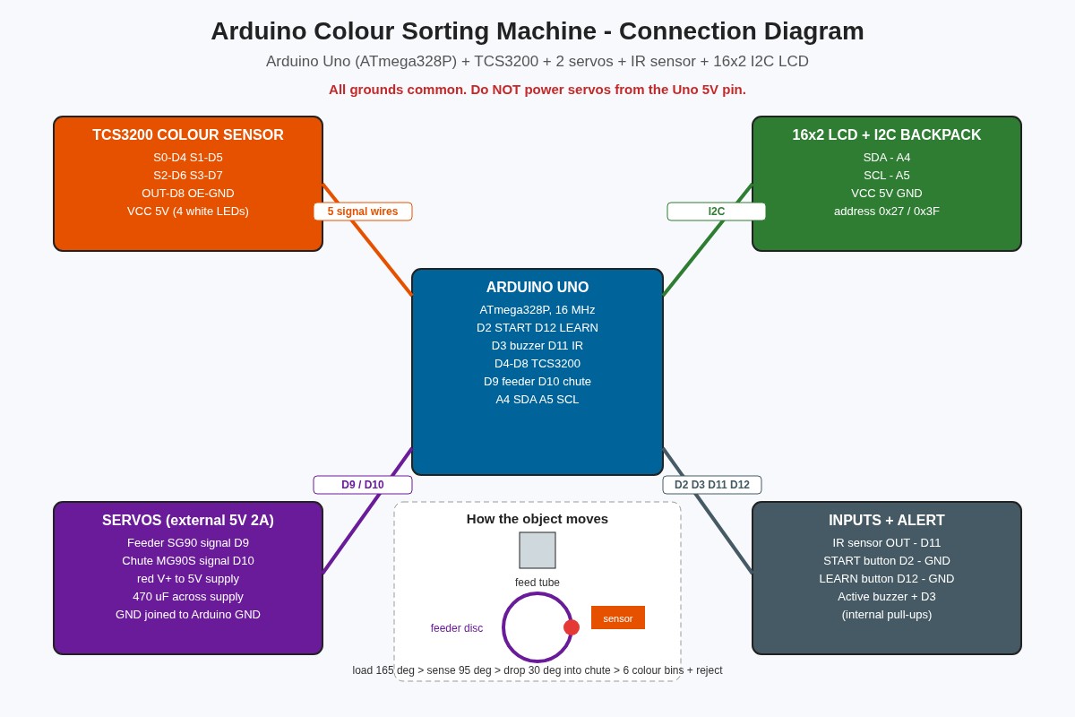
Connection diagram of the Arduino Uno colour sorting machine with TCS3200 colour sensor, feeder and chute servos, IR sensor, buttons, buzzer and 16x2 I2C LCD

Build an Arduino Uno colour sorting machine that feeds objects one by one, reads their colour with a TCS3200 sensor, turns a servo chute to the right bin and counts every colour on a 16×2 LCD, with a learn mode and EEPROM memory.

  • DifficultyAdvanced
  • Build time5–8 hours
  • Board / MCUArduino Uno (ATmega328P)
  • Parts12 items
  • CodeArduino C++

Need it ready-made? Buy Ready Project

Sorting things by colour is a real job in factories: sweets, plastic pellets, pharmacy capsules, beads and even recycled bottle caps are sorted by machines that look at each piece and push it into the right bin. This Arduino colour sorting machine is a desktop version of that idea. You pour objects into a tube, and the machine takes them one at a time, checks the colour, and drops each one into its own cup while the LCD keeps count.

It is a complete combination project: a TCS3200 colour sensor, two servo motors working in sequence, an IR sensor that knows when the tube is empty, two buttons, a buzzer and a 16×2 I2C LCD, all controlled by one ATmega328P. You will learn how a colour sensor turns light into frequency, how to calibrate a sensor with white and black references, nearest-colour matching, smooth servo motion and saving data in EEPROM.

Connection diagram of the Arduino Uno colour sorting machine with TCS3200 colour sensor, feeder and chute servos, IR sensor, buttons, buzzer and 16x2 I2C LCD

How It Works

  • Feeding: the top servo turns a disc with one hole in it. At 165° the hole sits under the feed tube and one object falls in. The disc then turns slowly to 95°, which carries the object under the colour sensor.
  • Presence check: an IR obstacle sensor looks into the hole at the sensing position. If nothing is there, the tube is empty: the machine beeps, shows Tube empty? and pauses until you refill it and press START.
  • Reading the colour: the TCS3200 has an 8×8 grid of photodiodes with red, green, blue and clear filters. Pins S2 and S3 select the filter, and the OUT pin gives a square wave whose frequency rises with the amount of light. The Arduino measures the period of that wave with pulseIn() for each filter, averaging 8 readings.
  • Normalising: raw periods depend on distance and lighting, so the sketch maps each one between your black-card and white-card readings to a value from 0 to 255. This makes the numbers stable and easy to compare.
  • Matching: the reading is compared with six learned reference colours (red, orange, yellow, green, blue and brown) using the sum of the R, G and B differences. The closest colour wins. If even the closest one is more than 60 points away, the object goes to the reject bin.
  • Sorting: the bottom servo turns the chute to the angle for that colour (20° to 170°, seven positions), then the feeder disc turns to 30° and the object drops down the chute into its cup.
  • Counting and memory: each bin has a counter shown on the LCD and printed on the Serial Monitor. Counters and the learned colours are saved in EEPROM, so they are still there after power-off. A long press (2 s) on START resets the counters.

Components Required

  • Arduino Uno R3 or Nano (ATmega328P, 16 MHz) – 1
  • TCS3200 / TCS230 colour sensor module (with 4 white LEDs) – 1
  • SG90 micro servo for the feeder disc – 1
  • MG90S metal-gear servo for the chute – 1
  • IR obstacle sensor module (FC-51 or similar) – 1
  • 16×2 LCD with I2C backpack (PCF8574, address 0x27 or 0x3F) – 1
  • 5 V active buzzer – 1
  • 12 mm tactile push buttons (START and LEARN) – 2
  • 5 V 2 A power supply or LM2596 buck converter for the servos – 1
  • 470 µF 16 V electrolytic capacitor (across the servo supply) – 1
  • Breadboard or perfboard, jumper wires and a white/black calibration card – 1 set
  • Frame: 3 mm MDF, acrylic or 3D-printed parts, a 12 mm feed tube and 7 small cups – 1 set

Wiring Table

Module / pinArduino Uno pinNotes
TCS3200 VCC / GND5V / GNDModule also powers its 4 white LEDs
TCS3200 S0D4HIGH together with S1 LOW = 20 % output scaling
TCS3200 S1D5LOW
TCS3200 S2D6Filter select
TCS3200 S3D7Filter select
TCS3200 OUTD8Square-wave output measured with pulseIn()
TCS3200 OEGNDOutput enable (active LOW); some modules tie it already
Feeder servo SG90 signalD9Red to external 5 V, brown to common GND
Chute servo MG90S signalD10Red to external 5 V, brown to common GND
IR sensor OUTD11VCC 5V, GND; output LOW when an object is in front
START buttonD2Other leg to GND, internal pull-up
LEARN buttonD12Other leg to GND, internal pull-up
Active buzzer +D3Buzzer – to GND (use a buzzer under 30 mA)
LCD I2C SDA / SCLA4 / A5VCC 5V, GND
External 5 V 2 A supply (–)GNDMust be joined to the Arduino GND

Pin check: D9 and D10 both work for servos because the Servo library uses Timer1 on the Uno. That also disables analogWrite() on D9 and D10, which this project does not need. The on-board LED on D13 lights while the machine is running.

Connection Diagram

The diagram above shows how the modules connect to the Arduino and how an object moves through the machine. The drawing below lists every pin exactly as used in the code.

Arduino Colour Sorting Machine – Pin-Accurate Wiring Arduino Uno D2 START button → GND (internal pull-up) D3 Active buzzer (+), buzzer (–) → GND D4 TCS3200 S0 (frequency scale) D5 TCS3200 S1 D6 TCS3200 S2 (filter select) D7 TCS3200 S3 D8 TCS3200 OUT (square wave); OE → GND D9 Feeder servo SG90 signal (orange wire) D10 Chute servo MG90S signal (orange wire) D11 IR obstacle sensor OUT (LOW = object) D12 LEARN button → GND (internal pull-up) A4 / A5 LCD I2C SDA / SCL 5V VCC of TCS3200, IR sensor and LCD only GND Common GND: Uno, sensors, LCD AND servo supply (–) External 5 V 2 A supply (+) → red wire of both servos (–) → servo brown wires + Uno GND 470 µF across (+) and (–) Never power the two servos from the Uno 5V pin: the current spikes reset the board and spoil colour readings. Mount the TCS3200 about 10–15 mm above the feeder hole and shade it from room light with a black tube or box.
Pin-accurate connection diagram for the Arduino colour sorting machine.

Building the Mechanism

  • Feed tube: a 12–15 mm plastic tube or a rolled card tube, a little wider than your objects. Fix it vertically above the feeder disc.
  • Feeder disc: a 50 mm round disc (MDF, acrylic or 3D print) with one hole slightly bigger than one object, screwed to the SG90 horn. Under the disc, a fixed base plate has no hole except at the drop position (30°), so the object rides in the hole until it reaches the chute.
  • Sensor window: mount the TCS3200 looking down on the hole at 95°, 10–15 mm above it, inside a small black shroud so room light does not change the reading. Put the IR sensor at the side of the same position.
  • Chute: a 120 mm half pipe (cut PVC pipe or folded card) glued to the MG90S horn. Arrange 7 cups in a half circle under the end of the chute.
  • Tune the angles: adjust FEED_LOAD, FEED_SENSE, FEED_DROP and CHUTE_ANGLE[] at the top of the sketch to match your build.

Code

Install LiquidCrystal I2C (by Frank de Brabander) from the Library Manager. Servo, Wire and EEPROM come with the Arduino IDE. Select Arduino Uno (or Nano, ATmega328P) and upload. The sketch was compile-checked for the Uno: about 11 KB of flash and 870 bytes of RAM.

/*
  Arduino Colour Sorting Machine
  TCS3200 colour sensor + 2 servos + 16x2 I2C LCD + IR presence sensor + buzzer
  Board: Arduino Uno / Nano (ATmega328P, 16 MHz)
  Arduino Project Hub - ardiunoprojecthub.online - Project #68

  How it works:
   1. The feeder servo picks one object (bead, candy, small block) from the tube
      and carries it under the TCS3200 colour sensor.
   2. The sensor measures red, green, blue and clear light. The sketch compares
      the reading with six learned reference colours (nearest match).
   3. The chute servo turns to the bin for that colour, the feeder drops the
      object, and the LCD shows the colour and the count for each bin.
   4. Counts and learned colours are kept in EEPROM, so they survive power-off.

  Buttons (to GND, internal pull-ups):
   START (D2)  : short press = run / pause, long press (2 s) = reset counters
   LEARN (D12) : hold while powering up = learn mode (teach the 6 colours)
*/

#include <Wire.h>
#include <Servo.h>
#include <EEPROM.h>
#include <LiquidCrystal_I2C.h>

// ---------------- Pin map ----------------
const uint8_t PIN_START  = 2;   // start / pause button
const uint8_t PIN_BUZZER = 3;   // active buzzer (+)
const uint8_t PIN_S0     = 4;   // TCS3200 frequency scaling
const uint8_t PIN_S1     = 5;
const uint8_t PIN_S2     = 6;   // TCS3200 photodiode filter select
const uint8_t PIN_S3     = 7;
const uint8_t PIN_OUT    = 8;   // TCS3200 square-wave output
const uint8_t PIN_FEED   = 9;   // feeder (top) servo signal
const uint8_t PIN_CHUTE  = 10;  // chute (bottom) servo signal
const uint8_t PIN_IR     = 11;  // IR obstacle sensor OUT (LOW = object present)
const uint8_t PIN_LEARN  = 12;  // learn button
const uint8_t PIN_LED    = 13;  // status LED (on-board)

// ---------------- Mechanics (tune for your build) ----------------
const uint8_t FEED_LOAD   = 165;  // feeder hole under the tube
const uint8_t FEED_SENSE  = 95;   // feeder hole under the colour sensor
const uint8_t FEED_DROP   = 30;   // feeder hole over the chute
const uint8_t CHUTE_ANGLE[7] = {20, 45, 70, 95, 120, 145, 170}; // 6 colours + reject bin

// ---------------- Colour table ----------------
const uint8_t NUM_COLOURS = 6;
const char* const COLOUR_NAME[7] = {"Red", "Orange", "Yellow", "Green", "Blue", "Brown", "Reject"};
const uint8_t REJECT = 6;
const uint16_t MATCH_LIMIT = 60;   // larger distance than this = unknown colour

struct Rgb { uint16_t r, g, b; };  // normalised values 0..255 (higher = more of that colour)

// Typical defaults for a TCS3200 at 20% scaling, ~15 mm above the object.
// Run learn mode once for best results with your own lighting and objects.
Rgb ref[NUM_COLOURS] = {
  {190,  60,  70}, {200, 110,  60}, {200, 185,  80},
  { 80, 170,  90}, { 60, 110, 200}, {120,  90,  80}
};

uint16_t binCount[7] = {0};

// ---------------- EEPROM layout ----------------
const uint16_t EE_MAGIC_ADDR = 0;     // 2 bytes
const uint16_t EE_REF_ADDR   = 2;     // 6 x 6 bytes
const uint16_t EE_COUNT_ADDR = 40;    // 7 x 2 bytes
const uint16_t EE_MAGIC      = 0xC068;

LiquidCrystal_I2C lcd(0x27, 16, 2);   // change to 0x3F if your LCD stays blank
Servo feeder, chute;

bool running = false;
uint16_t whiteRef[3] = {0, 0, 0};     // period (us) under white card, for normalising
uint16_t blackRef[3] = {0, 0, 0};     // period (us) under black card

// ---------------- Helpers ----------------
void beep(uint16_t ms) {
  digitalWrite(PIN_BUZZER, HIGH);
  delay(ms);
  digitalWrite(PIN_BUZZER, LOW);
}

void lcdLine(uint8_t row, const char* text) {
  lcd.setCursor(0, row);
  uint8_t n = 0;
  while (text[n] && n < 16) { lcd.write(text[n]); n++; }
  while (n < 16) { lcd.write(' '); n++; }    // clear the rest of the row
}

// Wait for a button press and its release (with debounce). Returns press time in ms.
uint32_t waitPress(uint8_t pin) {
  while (digitalRead(pin) == HIGH) {}
  delay(25);
  uint32_t t0 = millis();
  while (digitalRead(pin) == LOW) {}
  delay(25);
  return millis() - t0;
}

// Move a servo slowly so the object does not jump out of the feeder hole.
void moveSlow(Servo &s, uint8_t target) {
  int pos = s.read();
  int step = (target > pos) ? 1 : -1;
  while (pos != target) {
    pos += step;
    s.write(pos);
    delay(6);
  }
}

// Read one filter channel: average period of the OUT square wave in microseconds.
// Lower period = more light of that colour.
uint16_t readPeriod(bool s2, bool s3) {
  digitalWrite(PIN_S2, s2);
  digitalWrite(PIN_S3, s3);
  delay(5);                                  // let the filter settle
  uint32_t sum = 0;
  uint8_t ok = 0;
  for (uint8_t i = 0; i < 8; i++) {
    uint32_t p = pulseIn(PIN_OUT, LOW, 20000UL);
    if (p > 0) { sum += p; ok++; }
  }
  if (ok == 0) return 0xFFFF;               // no signal: sensor not wired or too dark
  return (uint16_t)(sum / ok);
}

// Raw periods for red, green and blue filters
void readRaw(uint16_t raw[3]) {
  raw[0] = readPeriod(LOW, LOW);      // red filter
  raw[1] = readPeriod(HIGH, HIGH);    // green filter
  raw[2] = readPeriod(LOW, HIGH);     // blue filter
}

// Convert periods to 0..255 using the black and white calibration
Rgb readColour() {
  uint16_t raw[3];
  readRaw(raw);
  uint16_t v[3];
  for (uint8_t i = 0; i < 3; i++) {
    long x = map((long)raw[i], (long)blackRef[i], (long)whiteRef[i], 0L, 255L);
    v[i] = (uint16_t)constrain(x, 0L, 255L);
  }
  Rgb c = {v[0], v[1], v[2]};
  return c;
}

// Nearest reference colour (Manhattan distance). Returns REJECT if nothing is close.
uint8_t classify(const Rgb &c, uint16_t &bestDist) {
  uint8_t best = REJECT;
  bestDist = 0xFFFF;
  for (uint8_t i = 0; i < NUM_COLOURS; i++) {
    uint16_t d = abs((int)c.r - (int)ref[i].r) +
                 abs((int)c.g - (int)ref[i].g) +
                 abs((int)c.b - (int)ref[i].b);
    if (d < bestDist) { bestDist = d; best = i; }
  }
  if (bestDist > MATCH_LIMIT) best = REJECT;
  return best;
}

// ---------------- EEPROM ----------------
void saveCounts() {
  for (uint8_t i = 0; i < 7; i++) EEPROM.put(EE_COUNT_ADDR + i * 2, binCount[i]);
}

void saveRefs() {
  EEPROM.put(EE_MAGIC_ADDR, EE_MAGIC);
  for (uint8_t i = 0; i < NUM_COLOURS; i++) EEPROM.put(EE_REF_ADDR + i * 6, ref[i]);
  // black/white calibration stored after the colour table
  EEPROM.put(EE_REF_ADDR + 36 + 16, whiteRef);
  EEPROM.put(EE_REF_ADDR + 36 + 22, blackRef);
}

bool loadEeprom() {
  uint16_t magic;
  EEPROM.get(EE_MAGIC_ADDR, magic);
  if (magic != EE_MAGIC) return false;
  for (uint8_t i = 0; i < NUM_COLOURS; i++) EEPROM.get(EE_REF_ADDR + i * 6, ref[i]);
  for (uint8_t i = 0; i < 7; i++) {
    EEPROM.get(EE_COUNT_ADDR + i * 2, binCount[i]);
    if (binCount[i] == 0xFFFF) binCount[i] = 0;
  }
  EEPROM.get(EE_REF_ADDR + 36 + 16, whiteRef);
  EEPROM.get(EE_REF_ADDR + 36 + 22, blackRef);
  return true;
}

// ---------------- Learn mode ----------------
// Step 1: white card, step 2: black card, steps 3..8: one sample of each colour.
void learnMode() {
  char buf[17];
  moveSlow(feeder, FEED_SENSE);

  lcdLine(0, "LEARN: put WHITE");
  lcdLine(1, "card, press LRN");
  waitPress(PIN_LEARN);
  readRaw(whiteRef);
  beep(60);

  lcdLine(0, "LEARN: put BLACK");
  lcdLine(1, "card, press LRN");
  waitPress(PIN_LEARN);
  readRaw(blackRef);
  beep(60);

  for (uint8_t i = 0; i < NUM_COLOURS; i++) {
    snprintf(buf, sizeof(buf), "LEARN: %s", COLOUR_NAME[i]);
    lcdLine(0, buf);
    lcdLine(1, "place, press LRN");
    waitPress(PIN_LEARN);
    // average three readings for a stable reference
    uint32_t r = 0, g = 0, b = 0;
    for (uint8_t k = 0; k < 3; k++) {
      Rgb c = readColour();
      r += c.r; g += c.g; b += c.b;
    }
    ref[i].r = r / 3; ref[i].g = g / 3; ref[i].b = b / 3;
    snprintf(buf, sizeof(buf), "R%3u G%3u B%3u", ref[i].r, ref[i].g, ref[i].b);
    lcdLine(1, buf);
    beep(60);
    delay(800);
  }
  saveRefs();
  lcdLine(0, "Colours saved!");
  lcdLine(1, "Press START");
  beep(200);
}

// ---------------- Display ----------------
void showIdle() {
  char buf[17];
  uint16_t total = 0;
  for (uint8_t i = 0; i < 7; i++) total += binCount[i];
  lcdLine(0, running ? "RUNNING" : "PAUSED - START");
  snprintf(buf, sizeof(buf), "Total sorted %u", total);
  lcdLine(1, buf);
}

// ---------------- Sort one object ----------------
void sortOne() {
  char buf[17];

  // 1. pick up an object from the tube
  moveSlow(feeder, FEED_LOAD);
  delay(400);

  // 2. carry it under the sensor
  moveSlow(feeder, FEED_SENSE);
  delay(300);

  // 3. is there really an object? (IR sensor looks into the feeder hole)
  if (digitalRead(PIN_IR) == HIGH) {
    lcdLine(0, "Tube empty?");
    lcdLine(1, "Refill & START");
    beep(400);
    running = false;
    return;
  }

  // 4. read and classify the colour
  Rgb c = readColour();
  uint16_t dist;
  uint8_t bin = classify(c, dist);

  snprintf(buf, sizeof(buf), "%-7s d=%u", COLOUR_NAME[bin], dist);
  lcdLine(0, buf);
  snprintf(buf, sizeof(buf), "R%3u G%3u B%3u", c.r, c.g, c.b);
  lcdLine(1, buf);

  Serial.print(F("RGB "));
  Serial.print(c.r); Serial.print(' ');
  Serial.print(c.g); Serial.print(' ');
  Serial.print(c.b);
  Serial.print(F(" -> "));
  Serial.println(COLOUR_NAME[bin]);

  // 5. turn the chute, then drop the object
  moveSlow(chute, CHUTE_ANGLE[bin]);
  delay(150);
  moveSlow(feeder, FEED_DROP);
  delay(350);

  binCount[bin]++;
  saveCounts();                // EEPROM.put only writes bytes that changed
  if (bin == REJECT) beep(150);

  snprintf(buf, sizeof(buf), "%s bin: %u", COLOUR_NAME[bin], binCount[bin]);
  lcdLine(1, buf);
}

// ---------------- Setup / loop ----------------
void setup() {
  Serial.begin(9600);
  pinMode(PIN_START, INPUT_PULLUP);
  pinMode(PIN_LEARN, INPUT_PULLUP);
  pinMode(PIN_IR, INPUT);
  pinMode(PIN_BUZZER, OUTPUT);
  pinMode(PIN_LED, OUTPUT);
  pinMode(PIN_S0, OUTPUT); pinMode(PIN_S1, OUTPUT);
  pinMode(PIN_S2, OUTPUT); pinMode(PIN_S3, OUTPUT);
  pinMode(PIN_OUT, INPUT);
  digitalWrite(PIN_S0, HIGH);  // 20% output frequency scaling (S0=H, S1=L)
  digitalWrite(PIN_S1, LOW);

  lcd.init();
  lcd.backlight();

  feeder.attach(PIN_FEED);
  chute.attach(PIN_CHUTE);
  feeder.write(FEED_SENSE);
  chute.write(CHUTE_ANGLE[3]);

  bool haveData = loadEeprom();
  if (!haveData) {
    // first power-up: sensible default periods (white ~ 40 us, black ~ 400 us)
    for (uint8_t i = 0; i < 3; i++) { whiteRef[i] = 40; blackRef[i] = 400; }
    for (uint8_t i = 0; i < 7; i++) binCount[i] = 0;
    saveRefs();            // write defaults so counts are kept from now on
    saveCounts();
  }

  lcdLine(0, "Colour Sorter");
  lcdLine(1, haveData ? "Data loaded" : "Defaults - LEARN");
  beep(80);
  delay(1200);

  if (digitalRead(PIN_LEARN) == LOW) {   // LEARN held at power-up
    while (digitalRead(PIN_LEARN) == LOW) {}
    delay(50);
    learnMode();
  }
  showIdle();
}

void loop() {
  // START button: short press toggles run/pause, long press resets the counters
  if (digitalRead(PIN_START) == LOW) {
    uint32_t held = waitPress(PIN_START);
    if (held > 2000) {
      for (uint8_t i = 0; i < 7; i++) binCount[i] = 0;
      saveCounts();
      running = false;
      lcdLine(0, "Counters reset");
      beep(300);
      delay(1000);
    } else {
      running = !running;
      beep(40);
    }
    showIdle();
  }

  digitalWrite(PIN_LED, running);
  if (running) {
    sortOne();
    if (!running) showIdle();
  }
}

Calibration and Testing

  • Learn mode: hold the LEARN button while you power up (or press reset), then release it. The LCD asks for a white card, then a black card, then one sample of each of the six colours. Place each one in the feeder hole under the sensor and press LEARN. The values are saved in EEPROM.
  • Check readings: open the Serial Monitor at 9600 baud. Each sorted object prints a line like RGB 192 64 71 -> Red. If two colours give very similar numbers (for example orange and brown), run learn mode again with better shading.
  • Run: press START to begin. The LED on D13 lights and the machine sorts about one object every 2–3 seconds. Press START again to pause; hold it for 2 seconds to reset the counters.
  • Tune the reject limit: raise MATCH_LIMIT if too many good objects go to reject, lower it if wrong colours slip into a bin.

Troubleshooting

ProblemFix
LCD backlight is on but no textTurn the blue contrast pot on the I2C backpack. If still blank, change the address in the sketch from 0x27 to 0x3F.
Arduino resets when the servos moveThe servos are drawing current from the Uno. Power them from a separate 5 V 2 A supply, join the grounds and add the 470 µF capacitor.
All readings are 0 or 255OUT is not reaching D8 or OE is not tied to GND. Check S0 to S3 wiring and that the four white LEDs on the module are lit.
Colour changes with room lightShade the sensor with a black tube or box and run learn mode again in the same lighting.
Every object goes to rejectLearn mode was skipped and the defaults do not match your objects. Hold LEARN at power-up and teach all six colours.
Machine says Tube empty? with objects presentAdjust the IR sensor’s blue trim pot until its LED turns on only when an object is in the hole. Matt black objects may need the sensor moved closer.
Objects jam between disc and baseMake the hole 1–2 mm bigger than the object and sand the edges. The slow servo movement in the code also helps.
Chute misses the cupsChange the values in CHUTE_ANGLE[] in 5° steps until each object lands in the middle of its cup.

Ideas to Extend

  • Add an HC-05 Bluetooth module to send the counts to a phone.
  • Replace the SG90 feeder with a small stepper motor for faster, more precise feeding.
  • Add a seventh learned colour (purple or white) by using the reject position as a real bin.

Wemos D1 Mini Bidirectional Visitor Counter with IR Sensors, OLED, Auto Light & Wi-Fi Dashboard

Wemos D1 Mini bidirectional visitor counter with two IR obstacle sensors on a door frame, OLED showing people inside, relay module with lamp, buzzer, BC547 and reset button

Build a Wemos D1 Mini bidirectional visitor counter that uses two IR sensors to tell entries from exits, shows people inside on an OLED, switches the room light on while anyone is inside, beeps at full capacity and serves a live Wi-Fi dashboard.

  • DifficultyAdvanced
  • Build time5–8 hours
  • Board / MCUWemos D1 Mini (ESP8266)
  • Parts11 items
  • CodeArduino C++

Need it ready-made? Buy Ready Project

Shops, classrooms, libraries and small offices often want to know how many people are inside right now, not just how many walked past the door. A single sensor cannot tell the difference between someone coming in and someone going out. This Wemos D1 Mini visitor counter uses two IR sensors placed side by side on the door frame, so it knows the direction of every person and keeps an accurate count of entries, exits and people inside.

It combines several useful features in one build: a 0.96″ OLED shows the live count, a relay switches the room light on as soon as the first person enters and off when the last one leaves (an easy energy saver), a buzzer warns when the room reaches its maximum capacity, and a Wi-Fi dashboard on your phone shows everything and lets you change the limit or reset the counts. Counts are saved to flash, so a power cut does not lose them.

Wemos D1 Mini bidirectional visitor counter with two IR obstacle sensors on a door frame, OLED showing people inside, relay module with lamp, buzzer, BC547 and reset button

How It Works

  • Two beams, one direction: sensor A faces across the outer edge of the door and sensor B across the inner edge. A person walking in blocks A first and then B. A person walking out blocks B first and then A.
  • State machine: the code waits in IDLE. If A goes LOW first it moves to A_FIRST and counts an entry when B is also blocked within 1.5 seconds. If B goes LOW first it counts an exit when A follows. It then waits until both beams are clear before it looks for the next person, so one person is never counted twice.
  • People inside: inside = entries − exits. Exits are never allowed to exceed entries, so the number cannot go negative after a false trigger.
  • Auto light: the relay on D7 is ON whenever at least one person is inside and OFF when the room is empty.
  • Capacity alarm: when inside reaches the maximum (20 by default) the buzzer gives a double beep for every new entry and the OLED and web page show FULL.
  • Wi-Fi dashboard: the D1 Mini runs a web server at its IP address and at http://visitors.local. The page asks /data every 2 seconds for a small JSON reply and has buttons to set the maximum capacity and reset the counts.
  • Saving counts: entries, exits and the maximum are stored in the ESP8266 EEPROM area every 5 minutes when they change, which keeps flash wear low. Hold the reset button for 2 seconds to clear them.

Components Required

  • Wemos D1 Mini (ESP8266) – 1
  • FC-51 IR obstacle sensor module (3.3–5 V) – 2
  • 0.96″ SSD1306 I2C OLED display (128×64) – 1
  • 5V single-channel relay module (opto/transistor input, works with 3.3 V signal) – 1
  • Active 5V buzzer – 1
  • BC547 NPN transistor + 1 kΩ resistor – 1 each
  • Tactile push button (reset) – 1
  • 5V 2A USB power supply – 1
  • Breadboard or perfboard, jumper wires and 3-core cable for the sensors – 1 set
  • Small enclosure and double-sided tape for mounting the sensors on the door frame – 1
  • LED bulb/lamp with holder for the relay (or use the existing room light through the relay, with care) – 1

Wiring Table

Module pinWemos D1 Mini pinNotes
IR sensor A VCC / GND / OUT5V / GND / D5 (GPIO14)Outside edge of door; OUT is LOW when blocked
IR sensor B VCC / GND / OUT5V / GND / D6 (GPIO12)Inside edge of door, 8–12 cm from A
OLED VCC / GND5V / GNDUse 3V3 if your OLED has no regulator
OLED SDA / SCLD2 (GPIO4) / D1 (GPIO5)I2C address 0x3C
Relay module VCC / GND / IN5V / GND / D7 (GPIO13)Choose a module that triggers from a 3.3 V signal
Relay COM / NOLamp live wire (switched)Lamp is ON when relay is energised
BC547 baseD8 (GPIO15) through 1 kΩEmitter to GND
Buzzer + / –5V / BC547 collectorActive buzzer
Reset buttonD3 (GPIO0) and GNDInternal pull-up; don’t hold it while powering up

Connection Diagram

The illustration above shows a typical breadboard layout and is a layout guide only. Follow the pin-accurate drawing below, which matches the wiring table and the code.

Wemos D1 Mini Bidirectional Visitor Counter – Pin-Accurate Wiring WEMOS D1 MINI 5V 5V to IR A/B VCC, relay VCC, buzzer +, OLED VCC GND Common ground for every module D5 GPIO14 IR sensor A (outside) OUT D6 GPIO12 IR sensor B (inside) OUT D2 GPIO4 OLED SDA D1 GPIO5 OLED SCL D7 GPIO13 Relay module IN (HIGH = light ON) D8 GPIO15 1 kΩ to BC547 base, buzzer – to collector D3 GPIO0 Reset button to GND (hold 2 s) IR sensors: mount A on the outside edge and B on the inside edge of the door frame, 8–12 cm apart, about 90 cm high. BC547: emitter to GND, collector to buzzer –, buzzer + to 5V. OLED here runs from 5V (most modules have a 3.3 V regulator). Relay contacts (COM/NO) switch the lamp. Mains wiring must be enclosed and done by a qualified person.
Pin-accurate connection diagram for the Wemos D1 Mini bidirectional visitor counter.

Mounting the Sensors

  • Fix both IR modules on the same side of the door frame at about waist height (85–100 cm) so they see a body, not legs or a swinging bag.
  • Keep them 8–12 cm apart along the direction of walking. Too close and both trigger at the same moment; too far and a slow person times out.
  • Point them across the doorway and turn each blue trimmer until the module’s LED just lights when you stand in the doorway and goes off when it is empty. For doors wider than about 30 cm, use E18-D80NK sensors (up to 80 cm) instead of FC-51.
  • Avoid direct sunlight on the sensors; IR modules get confused by strong sunlight.

Code

Install the ESP8266 board package in the Arduino IDE and the Adafruit SSD1306 and Adafruit GFX libraries. Select LOLIN(WEMOS) D1 R2 & mini, put your Wi-Fi name and password in place of the placeholders and upload. The sketch compiles for the D1 Mini with the ESP8266 core 3.1.2.

/*
  Wemos D1 Mini Bidirectional Visitor Counter
  2x IR obstacle sensors + 0.96" SSD1306 OLED + auto light relay + buzzer + Wi-Fi dashboard
  Arduino Project Hub - ardiunoprojecthub.online

  Pins (Wemos D1 Mini):
    IR sensor A (outside of door) OUT -> D5 (GPIO14)   (LOW = beam blocked)
    IR sensor B (inside of door)  OUT -> D6 (GPIO12)   (LOW = beam blocked)
    OLED SDA / SCL                    -> D2 (GPIO4) / D1 (GPIO5)
    Relay module IN (room light)      -> D7 (GPIO13)   (HIGH = light ON)
    Buzzer driver                     -> D8 (GPIO15) -> 1k -> BC547 base
    Reset button                      -> D3 (GPIO0) to GND (do not hold it while powering up)
*/
#include <ESP8266WiFi.h>
#include <ESP8266WebServer.h>
#include <ESP8266mDNS.h>
#include <EEPROM.h>
#include <Wire.h>
#include <Adafruit_GFX.h>
#include <Adafruit_SSD1306.h>

// ---------- Wi-Fi (replace the placeholders) ----------
const char* WIFI_SSID = "YOUR_WIFI_SSID";
const char* WIFI_PASS = "YOUR_WIFI_PASSWORD";

// ---------- Pins ----------
const uint8_t PIN_IR_A   = D5;   // outside sensor
const uint8_t PIN_IR_B   = D6;   // inside sensor
const uint8_t PIN_RELAY  = D7;   // room light relay
const uint8_t PIN_BUZZER = D8;   // buzzer transistor
const uint8_t PIN_RESET  = D3;   // reset counts button

// ---------- Settings ----------
const unsigned long PASS_TIMEOUT_MS = 1500;   // max time between sensor A and B for one person
const unsigned long SAVE_EVERY_MS   = 300000; // save counts to flash every 5 min if changed
int maxCapacity = 20;                         // buzzer warns when inside >= this (change from web)

Adafruit_SSD1306 oled(128, 64, &Wire, -1);
ESP8266WebServer server(80);

struct Counts { uint32_t magic; long entries; long exits; int maxCap; };
long entries = 0, exitsCount = 0;
bool dirty = false;
unsigned long lastSave = 0;

// direction state machine
enum State { IDLE, A_FIRST, B_FIRST, WAIT_CLEAR };
State state = IDLE;
unsigned long stateTime = 0;

long inside() { long n = entries - exitsCount; return n < 0 ? 0 : n; }

bool blockedA() { return digitalRead(PIN_IR_A) == LOW; }
bool blockedB() { return digitalRead(PIN_IR_B) == LOW; }

void beep(int ms) { digitalWrite(PIN_BUZZER, HIGH); delay(ms); digitalWrite(PIN_BUZZER, LOW); }

void loadCounts() {
  Counts c; EEPROM.get(0, c);
  if (c.magic == 0xC0FFEE65) { entries = c.entries; exitsCount = c.exits; maxCapacity = c.maxCap; }
}
void saveCounts() {
  Counts c = { 0xC0FFEE65, entries, exitsCount, maxCapacity };
  EEPROM.put(0, c); EEPROM.commit(); dirty = false; lastSave = millis();
}
void resetCounts() { entries = 0; exitsCount = 0; saveCounts(); beep(80); }

void updateOutputs() {
  digitalWrite(PIN_RELAY, inside() > 0 ? HIGH : LOW);   // light on while anyone is inside
}

void drawOled() {
  oled.clearDisplay();
  oled.setTextColor(SSD1306_WHITE);
  oled.setTextSize(1); oled.setCursor(0, 0); oled.print("INSIDE");
  oled.setCursor(80, 0); oled.print(inside() > 0 ? "LIGHT ON" : "LIGHT OFF");
  oled.setTextSize(3); oled.setCursor(0, 14); oled.print(inside());
  oled.setTextSize(1);
  oled.setCursor(0, 44); oled.print("IN:"); oled.print(entries);
  oled.setCursor(64, 44); oled.print("OUT:"); oled.print(exitsCount);
  oled.setCursor(0, 56);
  if (inside() >= maxCapacity) oled.print("FULL! max "); else oled.print("max ");
  oled.print(maxCapacity);
  if (WiFi.status() == WL_CONNECTED) { oled.setCursor(80, 56); oled.print("WiFi OK"); }
  oled.display();
}

void countEntry() {
  entries++; dirty = true; beep(40);
  if (inside() >= maxCapacity) { beep(150); delay(80); beep(150); }
}
void countExit() {
  if (exitsCount < entries) { exitsCount++; dirty = true; }
}

// Reads the two sensors and decides the direction of each person.
void handleSensors() {
  bool a = blockedA(), b = blockedB();
  unsigned long now = millis();
  switch (state) {
    case IDLE:
      if (a && !b) { state = A_FIRST; stateTime = now; }
      else if (b && !a) { state = B_FIRST; stateTime = now; }
      break;
    case A_FIRST:                       // outside first -> person coming in
      if (b) { countEntry(); state = WAIT_CLEAR; }
      else if (now - stateTime > PASS_TIMEOUT_MS) state = WAIT_CLEAR;
      break;
    case B_FIRST:                       // inside first -> person going out
      if (a) { countExit(); state = WAIT_CLEAR; }
      else if (now - stateTime > PASS_TIMEOUT_MS) state = WAIT_CLEAR;
      break;
    case WAIT_CLEAR:                    // wait until the doorway is empty again
      if (!a && !b) { state = IDLE; delay(50); }
      break;
  }
}

// ---------- Web dashboard ----------
const char PAGE[] PROGMEM = R"HTML(<!DOCTYPE html><html><head><meta name="viewport" content="width=device-width,initial-scale=1">
<title>Visitor Counter</title><style>body{font-family:Arial;background:#0f172a;color:#e2e8f0;text-align:center;margin:0;padding:16px}
.big{font-size:72px;font-weight:bold;color:#38bdf8}.row{display:flex;gap:10px;justify-content:center}
.card{background:#1e293b;border-radius:12px;padding:12px 18px;min-width:90px}.full{color:#f87171}
button,input{font-size:16px;padding:8px 12px;border-radius:8px;border:0;margin:6px}</style></head><body>
<h2>Room Visitor Counter</h2><div class="card"><div>People inside</div><div class="big" id="in">-</div><div id="st"></div></div><br>
<div class="row"><div class="card">Entries<br><b id="e">-</b></div><div class="card">Exits<br><b id="x">-</b></div><div class="card">Light<br><b id="l">-</b></div></div>
<p>Max capacity: <input id="m" type="number" min="1" max="500" style="width:80px"><button onclick="setMax()">Save</button></p>
<button onclick="if(confirm('Reset all counts?'))fetch('/reset').then(load)">Reset counts</button>
<script>function load(){fetch('/data').then(r=>r.json()).then(d=>{in_.textContent=d.inside;e.textContent=d.entries;x.textContent=d.exits;
l.textContent=d.light?'ON':'OFF';if(document.activeElement!==m)m.value=d.max;st.textContent=d.inside>=d.max?'ROOM FULL':'';st.className=d.inside>=d.max?'full':'';})}
var in_=document.getElementById('in');function setMax(){fetch('/setmax?v='+m.value).then(load)}load();setInterval(load,2000);</script></body></html>)HTML";

void handleRoot() { server.send_P(200, "text/html", PAGE); }
void handleData() {
  String j = "{\"inside\":" + String(inside()) + ",\"entries\":" + String(entries) +
             ",\"exits\":" + String(exitsCount) + ",\"max\":" + String(maxCapacity) +
             ",\"light\":" + String(inside() > 0 ? "true" : "false") + "}";
  server.send(200, "application/json", j);
}
void handleReset() { resetCounts(); server.send(200, "text/plain", "OK"); }
void handleSetMax() {
  int v = server.arg("v").toInt();
  if (v >= 1 && v <= 500) { maxCapacity = v; saveCounts(); }
  server.send(200, "text/plain", "OK");
}

void setup() {
  Serial.begin(115200);
  pinMode(PIN_IR_A, INPUT_PULLUP);
  pinMode(PIN_IR_B, INPUT_PULLUP);
  pinMode(PIN_RESET, INPUT_PULLUP);
  pinMode(PIN_RELAY, OUTPUT);  digitalWrite(PIN_RELAY, LOW);
  pinMode(PIN_BUZZER, OUTPUT); digitalWrite(PIN_BUZZER, LOW);

  EEPROM.begin(64);
  loadCounts();

  Wire.begin(D2, D1);
  if (!oled.begin(SSD1306_SWITCHCAPVCC, 0x3C)) Serial.println("OLED not found at 0x3C");
  oled.clearDisplay(); oled.setTextColor(SSD1306_WHITE); oled.setCursor(0, 0);
  oled.print("Connecting Wi-Fi..."); oled.display();

  WiFi.mode(WIFI_STA);
  WiFi.begin(WIFI_SSID, WIFI_PASS);
  unsigned long t = millis();
  while (WiFi.status() != WL_CONNECTED && millis() - t < 15000) delay(250);
  if (WiFi.status() == WL_CONNECTED) {
    Serial.print("Open http://"); Serial.println(WiFi.localIP());
    MDNS.begin("visitors");             // also http://visitors.local
  } else {
    Serial.println("Wi-Fi not connected - counter still works offline");
  }
  server.on("/", handleRoot);
  server.on("/data", handleData);
  server.on("/reset", handleReset);
  server.on("/setmax", handleSetMax);
  server.begin();
  updateOutputs();
  drawOled();
}

void loop() {
  handleSensors();
  server.handleClient();
  MDNS.update();

  if (digitalRead(PIN_RESET) == LOW) {          // long press 2 s = reset counts
    unsigned long t = millis();
    while (digitalRead(PIN_RESET) == LOW && millis() - t < 2000) delay(10);
    if (millis() - t >= 2000) resetCounts();
  }

  static unsigned long lastDraw = 0;
  if (millis() - lastDraw > 250) { updateOutputs(); drawOled(); lastDraw = millis(); }
  if (dirty && millis() - lastSave > SAVE_EVERY_MS) saveCounts();
}

Testing

  • Open the Serial Monitor at 115200 baud and note the IP address after “Open http://”.
  • Walk in slowly through the door: IN should rise by one, INSIDE should show 1, the relay should click and the lamp should turn on.
  • Walk out: OUT rises, INSIDE returns to 0 and the lamp turns off.
  • Set the maximum to 2 on the web page, walk in twice and check the double beep and the FULL message.
  • Hold the reset button for 2 seconds and check that all counts go to zero.

Troubleshooting

ProblemFix
Entries counted as exitsSensors A and B are swapped. Swap the D5 and D6 wires or swap the pin numbers in the code.
One person counted twiceMove the sensors a little further apart or increase the 50 ms delay in WAIT_CLEAR. Make sure both module LEDs go off when the doorway is empty.
Nothing counted when walking fastReduce the gap between the sensors or raise PASS_TIMEOUT_MS only if people walk very slowly; fast walking needs a smaller gap, not a longer timeout.
Relay does not switchSome relay modules need a 5 V signal. Use a module with an optocoupler or transistor input, or drive IN through a BC547 like the buzzer.
Board will not boot or uploadD3 (GPIO0) and D8 (GPIO15) are boot pins. Do not hold the reset button at power-up and keep the 1 kΩ base resistor on D8.
Web page does not openCheck the IP address in the Serial Monitor, keep the phone on the same Wi-Fi, and try the IP if visitors.local does not work on Android.
OLED stays blankCheck SDA on D2 and SCL on D1, and try address 0x3D if 0x3C is not found.

Ideas to Extend

  • Log hourly entries to Google Sheets or ThingSpeak for footfall reports.
  • Add a DS3231 RTC to reset the counts automatically at midnight.
  • Add a second relay for a fan, or a green/red LED at the door showing whether the room is full.

Arduino Nano Every Fridge Door Alarm with Reed Switch, Buzzer & Delay Knob

Arduino Nano Every fridge door alarm on a breadboard with reed switch and magnet on a fridge door, active buzzer with 2N2222, green and red LEDs, MUTE button and 10k potentiometer

Build a simple fridge door alarm with an Arduino Nano Every (ATmega4809) and a magnetic reed switch: it beeps when the fridge door is left open, gets louder after a while, has an adjustable delay knob and a 60-second mute button.

  • DifficultyEasy
  • Build time1–2 hours
  • Board / MCUArduino Nano Every (ATmega4809)
  • Parts10 items
  • CodeArduino C++

Need it ready-made? Buy Ready Project

Leaving the fridge door slightly open wastes electricity, makes the compressor work harder and spoils food. This Arduino Nano Every fridge door alarm fixes that with a tiny, low-cost circuit. A magnetic reed switch is stuck to the fridge body and a small magnet to the door. When the door opens, the magnet moves away, the switch opens and the ATmega4809 starts a timer. If the door is still open after the delay you set with a knob, a buzzer starts beeping.

It is a great small project for beginners: you learn digital inputs with internal pull-ups, debouncing, non-blocking timing with millis(), reading a potentiometer and driving a buzzer through a transistor. The same circuit works for a freezer, a cupboard, a main door or a cash drawer.

Arduino Nano Every fridge door alarm on a breadboard with reed switch and magnet on a fridge door, active buzzer with 2N2222, green and red LEDs, MUTE button and 10k potentiometer

How It Works

  • Door sensing (D2): the reed switch is wired between D2 and GND with the internal pull-up turned on. With the magnet close, the switch is closed and D2 reads LOW (door closed). When the door opens, the switch opens and D2 goes HIGH.
  • Debouncing: a change on D2 is accepted only after it stays the same for 50 ms, so door bumps and contact bounce do not cause false beeps.
  • Adjustable delay (A0): the 10 kΩ pot sets the allowed open time from 10 to 120 seconds. The code maps the 0–1023 reading to this range every loop, so you can turn the knob at any time.
  • Two alarm levels: while the door is open but within the delay, the red LED stays on. After the delay, the buzzer gives a short beep every second (WARNING). After twice the delay it beeps fast, five times per second (ALARM), so it is hard to ignore.
  • Mute button (D3): pressing it while the door is open silences the buzzer for 60 seconds, handy when you are loading groceries. The LEDs keep blinking to remind you.
  • Auto reset: closing the door switches the buzzer off, turns the green LED on and clears the mute timer, ready for the next opening.
  • Non-blocking code: everything runs on millis() with no long delay() calls, so the button and the door are checked hundreds of times per second.

Components Required

  • Arduino Nano Every (ATmega4809) – 1
  • Magnetic reed switch (door sensor, normally open) with magnet – 1
  • Active buzzer 5V – 1
  • 2N2222 (or BC547) NPN transistor + 1 kΩ base resistor – 1 set
  • Green and red 5 mm LEDs with 220 Ω resistors – 1 each
  • Tactile push button (MUTE) – 1
  • 10 kΩ potentiometer (delay knob) – 1
  • 5V USB adapter or USB power bank with micro-USB cable – 1
  • Small breadboard or perfboard, jumper wires and 2-core wire for the door – 1 set
  • Double-sided tape for the reed switch and magnet – 1

Wiring Table

Part / pinNano Every pinNotes
Reed switch leg 1D2Internal pull-up in code, no resistor needed
Reed switch leg 2GNDUse thin 2-core wire along the door seal
MUTE buttonD3 and GNDInternal pull-up
Green LED anodeD5 through 220 ΩCathode to GND – lit when door is closed
Red LED anodeD6 through 220 ΩCathode to GND – lit/blinking when door is open
2N2222 baseD9 through 1 kΩEmitter to GND
Active buzzer+ to 5V, – to 2N2222 collectorThe transistor lets a louder buzzer run without loading the pin
10 kΩ potEnds to 5V and GND, wiper to A0Turn right for a longer delay
PowerUSB connector5V USB adapter or power bank

Mounting tip: fix the reed switch on the fridge body near the handle side and the magnet on the door so they are within 10 mm of each other when the door is shut. Keep the main board outside the fridge, on top or on the side.

Connection Diagram

The illustration above shows the parts laid out on a breadboard. It is a layout guide only, so follow the pin-accurate drawing below, which matches the wiring table.

Arduino Nano Every Fridge Door Alarm – Pin-Accurate Wiring Nano Every 5V Pot left end; buzzer + pin GND Reed, button, LED cathodes, emitter, pot right end D2 Reed switch (other leg to GND) D3 MUTE button (other leg to GND) D5 220 Ω to green LED (door closed) D6 220 Ω to red LED (door open) D9 1 kΩ to 2N2222 base; buzzer – on collector A0 10 kΩ pot wiper (10–120 s delay) Power the Nano Every from a 5V USB adapter. Reed switch closed (magnet near) = door closed.
Pin-accurate connection diagram for the Arduino Nano Every fridge door alarm.

Code

In the Arduino IDE open Boards Manager, install Arduino megaAVR Boards, then select Tools → Board → Arduino Nano Every and keep Registers emulation at its default. No extra libraries are needed. The sketch uses about 4 KB of flash.

/*
  Arduino Nano Every (ATmega4809) Fridge Door Alarm
  Arduino Project Hub - ardiunoprojecthub.online

  Reed switch + magnet on the fridge door. If the door stays open
  longer than OPEN_WARN_MS the buzzer beeps slowly; after
  OPEN_ALARM_MS it beeps fast. The MUTE button silences the
  buzzer for SNOOZE_MS. Closing the door resets everything.

  Wiring:
    Reed switch  : D2 and GND (internal pull-up, LOW = door closed)
    MUTE button  : D3 and GND (internal pull-up)
    Active buzzer: D9 -> 1k -> 2N2222 base (buzzer on collector)
    Green LED    : D5 -> 220R -> LED -> GND (door closed)
    Red LED      : D6 -> 220R -> LED -> GND (door open)
    Delay pot    : 10k pot, ends on 5V/GND, wiper on A0 (10-120 s)
*/

const uint8_t PIN_REED   = 2;
const uint8_t PIN_MUTE   = 3;
const uint8_t PIN_GREEN  = 5;
const uint8_t PIN_RED    = 6;
const uint8_t PIN_BUZZER = 9;
const uint8_t PIN_POT    = A0;

const unsigned long DEBOUNCE_MS = 50;      // reed/button debounce time
const unsigned long SNOOZE_MS   = 60000UL; // mute time after button press
const unsigned long MIN_WARN_S  = 10;      // pot fully left
const unsigned long MAX_WARN_S  = 120;     // pot fully right

bool doorOpen = false;            // debounced door state
bool lastRawReed = false;
unsigned long reedChangedAt = 0;
unsigned long openedAt = 0;       // when the door was opened
unsigned long mutedUntil = 0;     // buzzer silent until this time
bool lastMute = HIGH;
unsigned long muteChangedAt = 0;

// Read the delay pot and turn it into a warning time in milliseconds
unsigned long warnDelayMs() {
  int raw = analogRead(PIN_POT);                       // 0..1023
  unsigned long s = MIN_WARN_S + (unsigned long)raw * (MAX_WARN_S - MIN_WARN_S) / 1023UL;
  return s * 1000UL;
}

void setup() {
  pinMode(PIN_REED, INPUT_PULLUP);
  pinMode(PIN_MUTE, INPUT_PULLUP);
  pinMode(PIN_GREEN, OUTPUT);
  pinMode(PIN_RED, OUTPUT);
  pinMode(PIN_BUZZER, OUTPUT);
  Serial.begin(9600);

  // Short start-up beep and LED test
  digitalWrite(PIN_GREEN, HIGH);
  digitalWrite(PIN_RED, HIGH);
  digitalWrite(PIN_BUZZER, HIGH);
  delay(150);
  digitalWrite(PIN_BUZZER, LOW);
  digitalWrite(PIN_RED, LOW);

  lastRawReed = (digitalRead(PIN_REED) == HIGH);   // HIGH = magnet away = open
  doorOpen = lastRawReed;
  openedAt = millis();
  Serial.println(F("Fridge door alarm ready"));
}

void loop() {
  unsigned long now = millis();

  // ---- Debounce the reed switch ----
  bool rawOpen = (digitalRead(PIN_REED) == HIGH);
  if (rawOpen != lastRawReed) {
    lastRawReed = rawOpen;
    reedChangedAt = now;
  }
  if ((now - reedChangedAt) > DEBOUNCE_MS && rawOpen != doorOpen) {
    doorOpen = rawOpen;
    if (doorOpen) {
      openedAt = now;
      Serial.println(F("Door OPEN"));
    } else {
      mutedUntil = 0;                       // reset snooze when closed
      Serial.println(F("Door CLOSED"));
    }
  }

  // ---- MUTE button (falling edge) ----
  bool mute = digitalRead(PIN_MUTE);
  if (mute != lastMute && (now - muteChangedAt) > DEBOUNCE_MS) {
    muteChangedAt = now;
    lastMute = mute;
    if (mute == LOW && doorOpen) {
      mutedUntil = now + SNOOZE_MS;
      Serial.println(F("Buzzer muted for 60 s"));
    }
  }

  // ---- LEDs and buzzer ----
  if (!doorOpen) {
    digitalWrite(PIN_GREEN, HIGH);
    digitalWrite(PIN_RED, LOW);
    digitalWrite(PIN_BUZZER, LOW);
    return;
  }

  digitalWrite(PIN_GREEN, LOW);
  unsigned long openFor = now - openedAt;
  unsigned long warnMs = warnDelayMs();
  bool muted = (mutedUntil != 0) && ((long)(mutedUntil - now) > 0);

  if (openFor < warnMs) {
    digitalWrite(PIN_RED, HIGH);            // open, still OK
    digitalWrite(PIN_BUZZER, LOW);
  } else if (openFor < warnMs * 2) {
    // WARNING: slow beep (150 ms every second), red LED blinks
    bool on = (openFor % 1000UL) < 150;
    digitalWrite(PIN_RED, (openFor % 1000UL) < 500);
    digitalWrite(PIN_BUZZER, (on && !muted) ? HIGH : LOW);
  } else {
    // ALARM: fast beep (100 ms on / 100 ms off), red LED fast blink
    bool on = (openFor % 200UL) < 100;
    digitalWrite(PIN_RED, on);
    digitalWrite(PIN_BUZZER, (on && !muted) ? HIGH : LOW);
  }
}

Testing

  • Open the Serial Monitor at 9600 baud. Move the magnet away from the reed switch: you should see Door OPEN and the red LED turns on.
  • Turn the pot fully left (10 s). Keep the magnet away: after 10 s the slow beep starts, after 20 s the fast beep starts.
  • Press MUTE: the buzzer stops for 60 seconds but the red LED keeps blinking.
  • Bring the magnet back: Door CLOSED appears, the buzzer stops and the green LED lights. Now set the pot to the delay you want, for example 30–60 seconds.

Troubleshooting

ProblemFix
Alarm says open even when the door is shutThe magnet is too far from the reed switch. Move them closer (under 10 mm) or use a stronger magnet. Check the switch type is normally open.
Buzzer never soundsCheck the transistor pins (E-B-C), the 1 kΩ base resistor and that the buzzer is an active type with + on 5V.
Random beeps when the door is closedLong door wires pick up noise. Twist the two wires, keep them away from the compressor cable, or add a 100 nF capacitor from D2 to GND.
Delay does not change with the knobCheck the pot wiper goes to A0 and the outer pins go to 5V and GND.
Upload fails on the Nano EverySelect Arduino Nano Every in the board menu, choose the right COM port and use a data USB cable, not a charge-only one.
MUTE button does nothingIt only works while the door is open. Check the button goes between D3 and GND on opposite legs.

Ideas to Extend

  • Add a DS18B20 sensor inside the fridge and beep if the temperature rises above 8 °C.
  • Count how many times the door is opened per day and store it in EEPROM.
  • Swap the Nano Every for a Wemos D1 Mini to get a phone notification when the door is left open.

ATmega16 Fire & Gas Safety System with MQ-2, Flame Sensor, LCD & Exhaust Fan

ATmega16 fire and gas safety system on a breadboard with MQ-2 gas sensor, flame sensor, LM35, 16x2 LCD showing SAFE, 2-channel relay with exhaust fan, buzzer, red and green LEDs and push button

Build an ATmega16 fire and gas safety system that watches an MQ-2 gas/smoke sensor, an IR flame sensor and an LM35 temperature sensor, shows the status on a 16×2 LCD, switches on an exhaust fan, closes a gas valve relay and sounds a latched alarm.

  • DifficultyAdvanced
  • Build time5–6 hours
  • Board / MCUATmega16 (8 MHz internal)
  • Parts15 items
  • CodeEmbedded C (AVR-GCC)

Need it ready-made? Buy Ready Project

This ATmega16 fire and gas safety system is a complete kitchen and workshop safety controller built around one 40-pin AVR chip. It watches three sensors at the same time: an MQ-2 module for LPG, smoke and other combustible gases, an IR flame sensor that sees an open flame, and an LM35 for room temperature. A 16×2 LCD shows the live gas level, temperature and system state, while a 2-channel relay module drives an exhaust fan and a gas solenoid valve (or a mains cut-off contactor).

When gas starts to build up, the fan switches on automatically and the buzzer gives a slow warning beep. If there is a flame, heavy gas or smoke, or a very high temperature, the system goes into a latched ALARM: the fan runs, the valve relay closes the gas supply, the red LED flashes and the buzzer sounds fast. The alarm stays on until the danger is gone and someone presses the RESET button, just like a real fire panel. It is a big combination project that teaches multi-channel ADC, sensor calibration, state machines, relay control and 4-bit LCD driving in plain AVR C.

Safety note: this is a learning project, not a certified gas or fire detector. Keep a certified smoke and LPG alarm installed, and let a qualified electrician do any 230V mains wiring.

ATmega16 fire and gas safety system on a breadboard with MQ-2 gas sensor, flame sensor, LM35, 16x2 LCD showing SAFE, 2-channel relay with exhaust fan, buzzer, red and green LEDs and push button

How It Works

  • Warm-up and auto-calibration: the MQ-2 heater needs about a minute to stabilise, so the LCD counts down 60 seconds while the LEDs blink. The ATmega16 then averages 200 readings from ADC0 in clean air and stores this as the baseline. All gas readings are shown as a rise above the baseline (for example Gas:+35), which makes the project work with any MQ-2 module.
  • Gas and smoke (PA0): the MQ-2 tin-dioxide element lowers its resistance when LPG, methane, propane, hydrogen or smoke reaches it, so the AOUT voltage rises. 16 samples are averaged every 100 ms to remove noise.
  • Temperature (PA1): the LM35 outputs 10 mV per °C. With the 5V AVCC reference each ADC step is about 4.9 mV, so the code converts it with temp = raw × 500 / 1023.
  • Flame (PD2): the flame module’s comparator output goes LOW when it sees the infrared light from a flame. The internal pull-up keeps the line HIGH otherwise.
  • Three states: SAFE (green LED, relays off), WARNING (gas rise of 80+ counts or 45 °C+: fan on and a slow beep) and ALARM (flame, gas rise of 220+ counts or 60 °C+: fan on, valve relay on, red LED flashing and a fast beep). All limits are #define values at the top of the code.
  • Latched alarm and silence: during an alarm, one press of the button mutes the buzzer for 60 seconds (an M appears on the LCD). After the sensors return to normal the alarm stays latched until you press the button again, so nobody misses a short event.
  • Fan run-on: after gas clears, the exhaust fan keeps running for 30 more seconds to push the remaining gas out of the room.

Components Required

  • ATmega16 microcontroller (40-pin DIP) – 1
  • USBasp programmer (10-pin to 6-pin adapter if needed) – 1
  • MQ-2 gas/smoke sensor module (with AOUT pin) – 1
  • IR flame sensor module (3-pin, DO output) – 1
  • LM35 temperature sensor (TO-92) – 1
  • 16×2 character LCD (HD44780) with 10 kΩ contrast pot – 1
  • 2-channel 5V relay module (opto-isolated) – 1
  • 12V DC exhaust fan (or small 5V fan for the demo) – 1
  • 12V solenoid gas valve (or any load for the demo) – 1
  • Active buzzer 5V + 2N2222 transistor + 1 kΩ resistor – 1 set
  • Red and green 5 mm LEDs with 220 Ω resistors – 1 each
  • Tactile push button (SILENCE / RESET) – 1
  • 10 kΩ resistor (RESET pull-up) and 100 nF capacitors – 1 and 3
  • 12V 2A adapter + LM7805 regulator (or 5V 2A supply) – 1
  • Large breadboard or perfboard and jumper wires – 1 set

Wiring Table

Part / pinATmega16 pinNotes
7805 output +5VVCC (10), AVCC (30)100 nF from each to GND; AREF (32) 100 nF to GND
GNDGND (11, 31)Common ground for sensors, relay module, LCD and 12V supply
RESETPin 910 kΩ to +5V (also to USBasp RESET)
MQ-2 AOUTPA0 / ADC0 (40)MQ-2 VCC to +5V (heater draws about 150 mA)
LM35 Vout (middle pin)PA1 / ADC1 (39)Left pin +5V, right pin GND (flat face towards you)
Flame sensor DOPD2 (16)Module VCC +5V, GND; set sensitivity with its blue pot
SILENCE / RESET buttonPD3 (17) and GNDInternal pull-up, no resistor needed
LCD RS / RW / ENPB0 (1) / GND / PB1 (2)LCD VSS GND, VDD +5V, V0 to 10 kΩ pot wiper
LCD D4, D5, D6, D7PB4, PB5, PB6, PB7 (5–8)D0–D3 unused; backlight A via 220 Ω to +5V, K to GND
Relay IN1 (exhaust fan)PC0 (22)Fan +12V through relay COM/NO
Relay IN2 (gas valve / cut-off)PC1 (23)Valve +12V through relay COM/NO
Relay module VCC / GND+5V / GNDActive-LOW inputs; set RELAY_ACTIVE_LOW 0 for active-HIGH boards
Buzzer driverPD5 (19)1 kΩ to 2N2222 base, emitter GND, buzzer between +5V and collector
Red ALARM LEDPD6 (20)Through 220 Ω, cathode to GND
Green SAFE LEDPD7 (21)Through 220 Ω, cathode to GND

Fuses: the code runs on the internal 8 MHz oscillator with JTAG disabled so all of PORTC is free: lfuse = 0xE4, hfuse = 0xD9. A fresh ATmega16 has JTAG enabled, which blocks PC2–PC5, so always set the fuses first.

Connection Diagram

The illustration above shows the parts laid out on a breadboard. It is a layout guide only, so follow the pin-accurate drawing below, which matches the wiring table.

ATmega16 Fire & Gas Safety System – Pin-Accurate Wiring ATmega16 VCC/AVCC (10,30) +5V from 7805; AREF (32) via 100 nF to GND GND (11,31) Common GND for all modules and supplies PA0 / ADC0 (40) MQ-2 module AOUT PA1 / ADC1 (39) LM35 middle pin (Vout) PB0 (1) LCD RS (pin 4); LCD RW (pin 5) to GND PB1 (2) LCD EN (pin 6) PB4-PB7 (5-8) LCD D4-D7 (pins 11-14) PC0 (22) Relay IN1 – exhaust fan PC1 (23) Relay IN2 – gas valve / cut-off PD2 / INT0 (16) Flame sensor DO (LOW = flame) PD3 (17) SILENCE/RESET button to GND PD5 (19) 1 kΩ to 2N2222 base; buzzer on collector PD6 (20) 220 Ω to red ALARM LED PD7 (21) 220 Ω to green SAFE LED RESET (9): 10 kΩ to +5V. Program with USBasp: MOSI PB5, MISO PB6, SCK PB7, RESET.
Pin-accurate connection diagram for the ATmega16 fire and gas safety system.

Code

The firmware is plain AVR C with no external libraries (about 1.9 KB of flash). Save it as main.c, then compile and flash it with avr-gcc and a USBasp:

avr-gcc -mmcu=atmega16 -Os -o main.elf main.c
avr-objcopy -O ihex -R .eeprom main.elf main.hex
avrdude -c usbasp -p m16 -U lfuse:w:0xE4:m -U hfuse:w:0xD9:m
avrdude -c usbasp -p m16 -U flash:w:main.hex:i

You can also use Microchip Studio: create a GCC C project for the ATmega16, paste the code and build. Keep F_CPU at 8000000 to match the fuses.

/*
 * ATmega16 Fire & Gas Safety System
 * MQ-2 gas/smoke sensor + IR flame sensor + LM35 temperature sensor,
 * 16x2 LCD, 2-channel relay (exhaust fan + gas valve / mains cut-off),
 * buzzer, LEDs and a SILENCE / RESET button.
 * ardiunoprojecthub.online
 *
 * MCU   : ATmega16 @ 8 MHz internal oscillator
 * Fuses : lfuse=0xE4 (internal 8 MHz), hfuse=0xD9 (JTAG off so PORTC is free)
 *
 * Pins
 *   MQ-2 AOUT        -> PA0 (ADC0)
 *   LM35 Vout        -> PA1 (ADC1)
 *   Flame sensor DO  -> PD2 (LOW = flame seen, internal pull-up on)
 *   SILENCE button   -> PD3 to GND (internal pull-up)
 *   LCD 16x2 4-bit   : RS=PB0, EN=PB1, D4=PB4, D5=PB5, D6=PB6, D7=PB7, RW=GND
 *   Relay CH1 (fan)  -> PC0
 *   Relay CH2 (valve)-> PC1
 *   Buzzer (active)  -> PD5 (via 2N2222 or direct if < 20 mA)
 *   Red LED ALARM    -> PD6 (220 ohm)
 *   Green LED SAFE   -> PD7 (220 ohm)
 *   AVCC -> 5V, AREF -> 100 nF to GND (AVCC used as ADC reference)
 *
 * States
 *   SAFE    : green LED, relays off.
 *   WARNING : gas rising or temperature high -> exhaust fan ON, slow beep.
 *   ALARM   : flame, heavy gas/smoke or very high temperature ->
 *             fan ON, gas valve relay CLOSES supply, fast beep, red LED.
 *   ALARM is latched: once conditions are safe again, press SILENCE/RESET
 *   to return to SAFE. While in ALARM, SILENCE mutes the buzzer for 60 s.
 */
#define F_CPU 8000000UL
#include <avr/io.h>
#include <util/delay.h>
#include <stdint.h>
#include <stdlib.h>

/* ---------- user settings ---------- */
#define WARMUP_S        60     /* MQ-2 heater warm-up time            */
#define GAS_WARN_DELTA  80     /* ADC counts above clean-air baseline */
#define GAS_ALARM_DELTA 220
#define TEMP_WARN_C     45
#define TEMP_ALARM_C    60
#define FAN_RUNON_S     30     /* fan keeps running after gas clears  */
#define SILENCE_S       60
#define RELAY_ACTIVE_LOW 1     /* most blue relay modules are active-LOW */

/* ---------- LCD (HD44780 4-bit on PORTB) ---------- */
#define LCD_RS PB0
#define LCD_EN PB1

static void lcd_pulse(void)
{
    PORTB |= (1 << LCD_EN); _delay_us(1);
    PORTB &= ~(1 << LCD_EN); _delay_us(50);
}
static void lcd_nibble(uint8_t n)
{
    PORTB = (PORTB & 0x0F) | (n & 0xF0);
    lcd_pulse();
}
static void lcd_byte(uint8_t b, uint8_t rs)
{
    if (rs) PORTB |= (1 << LCD_RS); else PORTB &= ~(1 << LCD_RS);
    lcd_nibble(b);
    lcd_nibble(b << 4);
    if (!rs && b < 4) _delay_ms(2);
}
static void lcd_cmd(uint8_t c)  { lcd_byte(c, 0); }
static void lcd_char(char c)    { lcd_byte((uint8_t)c, 1); }
static void lcd_goto(uint8_t col, uint8_t row) { lcd_cmd(0x80 | (row ? 0x40 : 0x00) | col); }
static void lcd_print(const char *s) { while (*s) lcd_char(*s++); }
static void lcd_line(uint8_t row, const char *s)
{   /* print a full 16-char line, padding with spaces (no flicker) */
    uint8_t i = 0;
    lcd_goto(0, row);
    while (*s && i < 16) { lcd_char(*s++); i++; }
    while (i++ < 16) lcd_char(' ');
}
static void lcd_init(void)
{
    DDRB |= 0xF3;                 /* PB0, PB1, PB4..PB7 outputs */
    _delay_ms(50);
    PORTB &= ~(1 << LCD_RS);
    lcd_nibble(0x30); _delay_ms(5);
    lcd_nibble(0x30); _delay_us(150);
    lcd_nibble(0x30); _delay_us(150);
    lcd_nibble(0x20);             /* 4-bit mode */
    lcd_cmd(0x28);                /* 2 lines, 5x8 font */
    lcd_cmd(0x0C);                /* display on, cursor off */
    lcd_cmd(0x06);                /* entry mode */
    lcd_cmd(0x01);                /* clear */
}

/* ---------- ADC ---------- */
static void adc_init(void)
{
    ADMUX  = (1 << REFS0);                                 /* AVCC ref */
    ADCSRA = (1 << ADEN) | (1 << ADPS2) | (1 << ADPS1);    /* 8 MHz/64 = 125 kHz */
}
static uint16_t adc_read(uint8_t ch)
{
    ADMUX = (1 << REFS0) | (ch & 0x07);
    _delay_us(20);
    ADCSRA |= (1 << ADSC);
    while (ADCSRA & (1 << ADSC));
    return ADC;
}
static uint16_t adc_avg(uint8_t ch, uint8_t n)
{
    uint32_t sum = 0;
    for (uint8_t i = 0; i < n; i++) sum += adc_read(ch);
    return (uint16_t)(sum / n);
}

/* ---------- outputs ---------- */
static void relay(uint8_t pin, uint8_t on)
{
#if RELAY_ACTIVE_LOW
    if (on) PORTC &= ~(1 << pin); else PORTC |= (1 << pin);
#else
    if (on) PORTC |= (1 << pin); else PORTC &= ~(1 << pin);
#endif
}
#define FAN   PC0
#define VALVE PC1
#define BUZ_ON()   (PORTD |=  (1 << PD5))
#define BUZ_OFF()  (PORTD &= ~(1 << PD5))
#define RED(x)     ((x) ? (PORTD |= (1 << PD6)) : (PORTD &= ~(1 << PD6)))
#define GREEN(x)   ((x) ? (PORTD |= (1 << PD7)) : (PORTD &= ~(1 << PD7)))
#define FLAME_SEEN()   (!(PIND & (1 << PD2)))
#define BTN_PRESSED()  (!(PIND & (1 << PD3)))

enum { SAFE, WARNING, ALARM };

static void beep(uint16_t ms) { BUZ_ON(); while (ms--) _delay_ms(1); BUZ_OFF(); }

int main(void)
{
    char num[7];

    /* I/O setup */
    DDRC |= (1 << FAN) | (1 << VALVE);
    relay(FAN, 0); relay(VALVE, 0);
    DDRD |= (1 << PD5) | (1 << PD6) | (1 << PD7);
    DDRD &= ~((1 << PD2) | (1 << PD3));
    PORTD |= (1 << PD2) | (1 << PD3);           /* pull-ups */

    lcd_init();
    adc_init();

    /* ---- warm-up of the MQ-2 heater ---- */
    lcd_line(0, "Fire&Gas Safety");
    for (int s = WARMUP_S; s > 0; s--) {
        itoa(s, num, 10);
        lcd_line(1, "");
        lcd_goto(0, 1); lcd_print("Warm-up "); lcd_print(num); lcd_print(" s");
        RED(s & 1); GREEN(!(s & 1));
        _delay_ms(1000);
    }

    /* ---- learn clean-air baseline ---- */
    lcd_line(1, "Calibrating...");
    uint32_t sum = 0;
    for (uint16_t i = 0; i < 200; i++) { sum += adc_read(0); _delay_ms(5); }
    uint16_t baseline = (uint16_t)(sum / 200);
    RED(0); GREEN(1);
    beep(100);

    uint8_t  state = SAFE, latched = 0;
    uint16_t fan_runon = 0, silence = 0;   /* in 100 ms ticks */
    uint8_t  tick = 0, btn_prev = 0;

    for (;;) {
        /* ---- read sensors (every 100 ms) ---- */
        uint16_t gas  = adc_avg(0, 16);
        int16_t  diff = (int16_t)gas - (int16_t)baseline;
        if (diff < 0) diff = 0;
        uint16_t traw = adc_avg(1, 16);
        int16_t  temp = (int16_t)((traw * 500UL) / 1023);   /* LM35: 10 mV/C */
        uint8_t  flame = FLAME_SEEN();

        /* ---- decide state ---- */
        uint8_t now;
        if (flame || diff >= GAS_ALARM_DELTA || temp >= TEMP_ALARM_C) now = ALARM;
        else if (diff >= GAS_WARN_DELTA || temp >= TEMP_WARN_C)      now = WARNING;
        else                                                          now = SAFE;

        if (now == ALARM) { latched = 1; }
        if (latched) state = ALARM; else state = now;

        /* ---- button: silence buzzer or reset latched alarm ---- */
        uint8_t btn = BTN_PRESSED();
        if (btn && !btn_prev) {
            if (latched && now != ALARM) { latched = 0; state = now; silence = 0; beep(60); }
            else if (state == ALARM) { silence = SILENCE_S * 10; }
        }
        btn_prev = btn;
        if (silence) silence--;

        /* ---- outputs ---- */
        if (state != SAFE || diff >= GAS_WARN_DELTA) fan_runon = FAN_RUNON_S * 10;
        else if (fan_runon) fan_runon--;
        relay(FAN, fan_runon > 0);
        relay(VALVE, state == ALARM);           /* close gas / cut supply */

        GREEN(state == SAFE);
        if (state == ALARM)        { RED(tick & 2); if (!silence && (tick & 2)) BUZ_ON(); else BUZ_OFF(); }
        else if (state == WARNING) { RED(tick < 2); if (tick == 0) BUZ_ON(); else BUZ_OFF(); }
        else                       { RED(0); BUZ_OFF(); }

        /* ---- LCD every 500 ms ---- */
        if (tick % 5 == 0) {
            const char *msg;
            if (state == ALARM)
                msg = flame ? "!! FIRE ALARM !!" : (diff >= GAS_ALARM_DELTA ? "!! GAS  ALARM !!" :
                      (temp >= TEMP_ALARM_C ? "!! HEAT ALARM !!" : "ALARM-press RST "));
            else if (state == WARNING) msg = "WARNING  Fan ON ";
            else msg = fan_runon ? "SAFE    Fan ON  " : "SAFE  All normal";
            lcd_line(0, msg);

            /* line 2: "Gas:+123 T:31C F" */
            itoa(diff, num, 10);
            lcd_goto(0, 1);
            lcd_print("Gas:+"); lcd_print(num); lcd_print("   ");
            lcd_goto(9, 1);
            itoa(temp, num, 10);
            lcd_print("T:"); lcd_print(num); lcd_print("C");
            lcd_print(temp < 10 ? "  " : (temp < 100 ? " " : ""));
            lcd_goto(15, 1);
            lcd_char(flame ? 'F' : (silence ? 'M' : ' '));
        }

        if (++tick >= 10) tick = 0;
        _delay_ms(100 - 20);   /* ~100 ms loop including ADC time */
    }
}

Testing and Calibration

  • Power up in clean air. After the warm-up the LCD should read SAFE All normal with a gas value close to +0 and the room temperature.
  • Gas test: hold an unlit lighter near the MQ-2 and press its gas button briefly (do not light it). The gas value rises, the fan relay clicks on (WARNING) and, with more gas, the system goes to GAS ALARM and the valve relay turns on.
  • Flame test: light a candle about 30–50 cm in front of the flame sensor. Its DO LED lights and the LCD shows FIRE ALARM. Adjust the module’s pot so normal room light does not trigger it.
  • Heat test: warm the LM35 gently with your fingers or a hair dryer on low to see the temperature go up; lower TEMP_WARN_C temporarily to test the warning.
  • Press the button during an alarm to mute it, then again after the reading is normal to reset. Tune GAS_WARN_DELTA and GAS_ALARM_DELTA to suit your room.

Troubleshooting

ProblemFix
LCD shows black boxes or nothingTurn the 10 kΩ contrast pot. Check RW is tied to GND and the D4–D7 lines go to PB4–PB7 in order.
LCD garbled or code runs very slowlyThe fuses are still at 1 MHz or the clock does not match F_CPU. Program lfuse 0xE4 and hfuse 0xD9.
Relays click the wrong way (on when SAFE)Your relay board is active-HIGH. Change RELAY_ACTIVE_LOW to 0 and rebuild.
Goes to GAS ALARM right after startIt calibrated in dirty air or the MQ-2 is new. Burn in a new sensor for 24–48 hours, then reset the ATmega16 in fresh air.
FIRE ALARM in sunlight or bright lampSunlight contains infrared. Turn the flame module’s pot to lower sensitivity and point it away from windows.
Temperature reads 0 or jumps a lotCheck the LM35 pin order and add a 100 nF capacitor from its output to GND. Keep its wires away from the relay wires.
Controller resets when the fan or valve switchesFeed the 12V loads from their own supply, keep only GND common, add a flyback diode across the solenoid valve and a 470 µF capacitor on the 5V rail.

Ideas to Extend

  • Add a SIM800L GSM module on the ATmega16 UART (PD0/PD1) to send an SMS on alarm.
  • Log alarm events with a time stamp using a DS1307 RTC and the internal EEPROM.
  • Add a second MQ-2 in another room on ADC2 and show which zone is in alarm.

Arduino Breathalyzer with MQ-3 Alcohol Sensor, I2C LCD & Buzzer

Arduino Uno breathalyzer on a breadboard with MQ-3 alcohol sensor module, green, yellow and red LEDs, active buzzer, push button and 16x2 I2C LCD showing CLEAR

Build an Arduino breathalyzer with an MQ-3 alcohol sensor that warms up, calibrates itself in clean air, runs a 5-second blow test and shows CLEAR, LOW or HIGH on a 16×2 I2C LCD with LEDs and a buzzer.

  • DifficultyMedium
  • Build time2–3 hours
  • Board / MCUArduino Uno (ATmega328P)
  • Parts10 items
  • CodeArduino C++

Need it ready-made? Buy Ready Project

This Arduino breathalyzer uses the MQ-3 alcohol sensor to detect ethanol vapour in a breath sample. After a 60-second heater warm-up it learns the clean-air reading by itself, then you press a button and blow for 5 seconds. The Arduino records the peak reading, compares it with the clean-air baseline and shows CLEAR, ALCOHOL LOW or ALCOHOL HIGH on a 16×2 I2C LCD, lights a green, yellow or red LED and beeps a matching pattern.

It is a great medium-level project to learn analog sensors, averaging and noise filtering, auto-calibration, peak detection and I2C displays. Important: this is an educational vapour indicator, not a certified breath alcohol tester. Its readings change with temperature, humidity and sensor age, so never use it to decide whether anyone is fit to drive.

Arduino Uno breathalyzer on a breadboard with MQ-3 alcohol sensor module, green, yellow and red LEDs, active buzzer, push button and 16x2 I2C LCD showing CLEAR

How It Works

  • MQ-3 sensor: inside the metal mesh is a tin dioxide (SnO2) element with a small heater. When alcohol vapour reaches the hot surface its resistance drops, so the voltage on the module’s AOUT pin rises. The Arduino reads it on A0 as a number from 0 to 1023.
  • Warm-up: the heater needs time to reach a stable temperature, so the LCD counts down 60 seconds with the yellow LED on. A brand-new sensor should be powered for 24–48 hours once (burn-in) before readings settle.
  • Auto-calibration: the sketch averages 500 readings in clean air and stores that as the baseline. Every result is shown as a rise above this baseline, so the project works even though every MQ-3 module reads a little differently.
  • Blow test: press the button, wait for the beep and blow steadily for 5 seconds from about 2–3 cm away. The yellow LED blinks while the Arduino samples and keeps the highest reading (the peak).
  • Result: a rise under 60 counts is CLEAR (green, one short beep), 60–199 is LOW (yellow, two beeps) and 200 or more is HIGH (red, five beeps). A 0–100% level bar value is also shown. The thresholds are constants at the top of the code, so you can tune them.
  • Recovery: after a test the sensor needs a few seconds to clear. The sketch waits until the reading falls back near the baseline before it shows Ready again, so a second test is not falsely high.

Components Required

  • Arduino Uno R3 (or Nano, ATmega328P) – 1
  • MQ-3 alcohol sensor module (with AOUT pin) – 1
  • 16×2 LCD with I2C backpack (PCF8574, address 0x27 or 0x3F) – 1
  • Green, yellow and red 5 mm LEDs – 1 each
  • 220 Ω resistors – 3
  • Active buzzer 5V – 1
  • Tactile push button 12 mm – 1
  • Half-size breadboard – 1
  • Jumper wires (male-to-male and male-to-female) – 15
  • USB cable or 9V 1A adapter (MQ-3 heater draws about 150 mA) – 1

Wiring Table

Part / pinArduino pinNotes
MQ-3 VCC5VHeater needs a full 5V; 3.3V will not work
MQ-3 GNDGND
MQ-3 AOUTA0Analog output; DOUT pin is not used
LCD I2C VCC / GND5V / GND
LCD I2C SDAA4On the Uno R3 SDA is also next to AREF
LCD I2C SCLA5
Push buttonD2 and GNDInternal pull-up, no resistor needed
Green LED (via 220 Ω)D5Cathode (short leg) to GND
Yellow LED (via 220 Ω)D6Cathode to GND
Red LED (via 220 Ω)D7Cathode to GND
Active buzzer + / –D8 / GNDUse an active (self-oscillating) buzzer

Connection Diagram

The illustration above shows the parts laid out on the breadboard. It is a layout guide only, so follow the pin-accurate drawing below, which matches the wiring table.

Arduino MQ-3 Breathalyzer – Pin-Accurate Wiring Arduino Uno 5V MQ-3 VCC and LCD VCC (5V rail) GND GND rail: MQ-3, LCD, button, LEDs, buzzer A0 MQ-3 module AOUT (analog output) A4 (SDA) I2C LCD SDA A5 (SCL) I2C LCD SCL D2 Push button to GND (internal pull-up) D5 220 Ω to green LED anode, cathode to GND D6 220 Ω to yellow LED anode, cathode to GND D7 220 Ω to red LED anode, cathode to GND D8 Active buzzer +, buzzer – to GND
Pin-accurate connection diagram for the Arduino MQ-3 breathalyzer.

Code

In the Arduino IDE open Library Manager and install LiquidCrystal I2C (by Frank de Brabander). Select Arduino Uno as the board, paste the sketch and upload. Open the Serial Monitor at 9600 baud to see the baseline and each test result.

/*
  Arduino Breathalyzer with MQ-3 Alcohol Sensor, I2C LCD & Buzzer
  Arduino Project Hub - ardiunoprojecthub.online

  Educational alcohol-vapour indicator. NOT a legal or medical breath test:
  never use it to decide whether someone is fit to drive.

  Wiring:
    MQ-3 module  VCC -> 5V, GND -> GND, AOUT -> A0
    I2C LCD 16x2 VCC -> 5V, GND -> GND, SDA -> A4, SCL -> A5
    Push button  D2 -> GND (internal pull-up)
    Green LED    D5 -> 220R -> GND
    Yellow LED   D6 -> 220R -> GND
    Red LED      D7 -> 220R -> GND
    Active buzzer + -> D8, - -> GND
*/
#include <Wire.h>
#include <LiquidCrystal_I2C.h>

const uint8_t PIN_MQ3    = A0;
const uint8_t PIN_BTN    = 2;
const uint8_t PIN_GREEN  = 5;
const uint8_t PIN_YELLOW = 6;
const uint8_t PIN_RED    = 7;
const uint8_t PIN_BUZZ   = 8;

const uint16_t WARMUP_S     = 60;    // heater warm-up time (longer on first use)
const uint16_t BLOW_MS      = 5000;  // how long the user blows
const int      LOW_DELTA    = 60;    // ADC rise above baseline for "LOW"
const int      HIGH_DELTA   = 200;   // ADC rise above baseline for "HIGH"

LiquidCrystal_I2C lcd(0x27, 16, 2);  // change to 0x3F if the screen stays blank
int baseline = 0;

int readAvg(uint8_t n) {             // average n readings to reduce noise
  long sum = 0;
  for (uint8_t i = 0; i < n; i++) { sum += analogRead(PIN_MQ3); delay(5); }
  return sum / n;
}

void setLeds(bool g, bool y, bool r) {
  digitalWrite(PIN_GREEN, g);
  digitalWrite(PIN_YELLOW, y);
  digitalWrite(PIN_RED, r);
}

void beep(uint8_t times, uint16_t onMs) {
  for (uint8_t i = 0; i < times; i++) {
    digitalWrite(PIN_BUZZ, HIGH); delay(onMs);
    digitalWrite(PIN_BUZZ, LOW);  delay(onMs);
  }
}

void calibrate() {                   // learn the clean-air reading
  lcd.clear();
  lcd.print("Calibrating...");
  lcd.setCursor(0, 1);
  lcd.print("Keep clean air");
  long sum = 0;
  for (uint8_t i = 0; i < 50; i++) { sum += readAvg(10); delay(40); }
  baseline = sum / 50;
  Serial.print(F("Baseline ADC: "));
  Serial.println(baseline);
}

void warmUp() {
  setLeds(false, true, false);
  for (int s = WARMUP_S; s > 0; s--) {
    lcd.setCursor(0, 0);
    lcd.print("Sensor warm-up  ");
    lcd.setCursor(0, 1);
    lcd.print("Wait ");
    lcd.print(s);
    lcd.print(" s       ");
    delay(1000);
  }
}

void showReady() {
  setLeds(true, false, false);
  lcd.clear();
  lcd.print("Ready. Press btn");
  lcd.setCursor(0, 1);
  lcd.print("Base: ");
  lcd.print(baseline);
}

void runTest() {
  lcd.clear();
  lcd.print("Blow steadily");
  beep(1, 150);
  int peak = 0;
  unsigned long start = millis();
  while (millis() - start < BLOW_MS) {
    int v = readAvg(5);
    if (v > peak) peak = v;
    uint8_t left = (BLOW_MS - (millis() - start)) / 1000 + 1;
    lcd.setCursor(0, 1);
    lcd.print("ADC ");
    lcd.print(v);
    lcd.print("  ");
    lcd.print(left);
    lcd.print("s   ");
    setLeds(false, (millis() / 250) % 2, false);   // blink yellow while sampling
  }

  int delta = peak - baseline;
  if (delta < 0) delta = 0;
  uint8_t percent = constrain(map(delta, 0, 600, 0, 100), 0, 100);

  lcd.clear();
  lcd.print("Peak ");
  lcd.print(peak);
  lcd.print(" (+");
  lcd.print(delta);
  lcd.print(")");
  lcd.setCursor(0, 1);
  if (delta < LOW_DELTA) {
    lcd.print("CLEAR       ");
    setLeds(true, false, false);
    beep(1, 80);
  } else if (delta < HIGH_DELTA) {
    lcd.print("ALCOHOL LOW ");
    setLeds(false, true, false);
    beep(2, 150);
  } else {
    lcd.print("ALCOHOL HIGH");
    setLeds(false, false, true);
    beep(5, 200);
  }
  lcd.setCursor(12, 1);
  if (percent < 100) lcd.print(" ");
  if (percent < 10) lcd.print(" ");
  lcd.print(percent);
  lcd.print("%");

  Serial.print(F("Peak: ")); Serial.print(peak);
  Serial.print(F("  Delta: ")); Serial.print(delta);
  Serial.print(F("  Level: ")); Serial.print(percent); Serial.println(F("%"));

  delay(4000);
  // wait until the sensor has recovered close to baseline before the next test
  lcd.clear();
  lcd.print("Clearing sensor");
  while (readAvg(10) > baseline + LOW_DELTA / 2) {
    lcd.setCursor(0, 1);
    lcd.print("ADC ");
    lcd.print(readAvg(10));
    lcd.print("     ");
    delay(500);
  }
  showReady();
}

void setup() {
  Serial.begin(9600);
  pinMode(PIN_BTN, INPUT_PULLUP);
  pinMode(PIN_GREEN, OUTPUT);
  pinMode(PIN_YELLOW, OUTPUT);
  pinMode(PIN_RED, OUTPUT);
  pinMode(PIN_BUZZ, OUTPUT);

  lcd.init();
  lcd.backlight();
  lcd.print("MQ-3 Breath Test");
  lcd.setCursor(0, 1);
  lcd.print("Project Hub");
  delay(1500);

  warmUp();
  calibrate();
  showReady();
}

void loop() {
  if (digitalRead(PIN_BTN) == LOW) {         // button pressed
    delay(30);                               // debounce
    if (digitalRead(PIN_BTN) == LOW) {
      while (digitalRead(PIN_BTN) == LOW) {} // wait for release
      runTest();
    }
  }
}

Testing and Calibration

  • Power the circuit in clean air, away from perfume, hand sanitiser and cooking fumes. The LCD counts down the warm-up and then shows Ready with the baseline value (typically 100–300).
  • Press the button and blow normally. With clean breath the result should be CLEAR.
  • To test the alarm safely, rub a little hand sanitiser on a cotton bud and hold it about 2 cm from the sensor during the 5-second test. The reading should rise to LOW or HIGH.
  • If results feel too sensitive or not sensitive enough, change LOW_DELTA and HIGH_DELTA. You can also turn the small potentiometer on the module, which changes its load resistance, then restart so it recalibrates.

Troubleshooting

ProblemFix
LCD backlight on but no textTurn the blue contrast pot on the I2C backpack. If still blank, change the address in the code from 0x27 to 0x3F (run an I2C scanner to check).
Baseline keeps rising for minutesThe sensor is still warming. Let a new MQ-3 burn in for 24–48 hours once, or increase WARMUP_S to 180.
Always shows ALCOHOL HIGHIt calibrated in dirty air (sanitiser, perfume nearby). Move to fresh air and press reset to recalibrate.
Reading never changesCheck AOUT goes to A0, not DOUT. The sensor should feel warm after a minute; if not, check 5V and GND.
Arduino resets or LCD flickersThe heater draws about 150 mA. Use a good USB port or a 9V 1A adapter instead of a weak power bank.
Stuck on Clearing sensorWave fresh air over the sensor. If the room air changed, press reset to take a new baseline.

Ideas to Extend

  • Add a DHT22 sensor and correct the reading for temperature and humidity.
  • Store the last 10 results in the ATmega328P EEPROM and show them with a second button.
  • Replace the Uno with an ESP32 to log readings to a phone over Wi-Fi.

ESP32 Smart Pet Feeder with Load Cell, Servo, OLED & Web Schedule

ESP32 smart pet feeder with servo-driven kibble hopper, bowl on a load cell with HX711, OLED display, buzzer, button and a phone showing the meal schedule web page

Build an ESP32 smart pet feeder that serves up to four scheduled meals, weighs every portion with a load cell, shows the bowl weight on an OLED and lets you feed or change the schedule from your phone.

  • DifficultyAdvanced
  • Build time5–7 hours
  • Board / MCUESP32 DevKit V1
  • Parts13 items
  • CodeArduino C++

Need it ready-made? Buy Ready Project

This ESP32 smart pet feeder feeds your dog or cat on time even when nobody is home. A servo opens a gate under a kibble hopper, and the bowl sits on a load cell, so the ESP32 keeps the gate open until the bowl has gained exactly the grams you asked for. You get up to four meals a day, a small OLED that shows the bowl weight and the next meal, a chime that calls your pet, and a phone web page to change the schedule or press Feed now.

It is a big combination project: Wi-Fi and NTP time, a weighing scale, a motor, a display and a web app all running on one board. Because it measures food by weight instead of by servo time, every portion is the same size no matter how full the hopper is, and it can tell you when the hopper is empty or jammed.

ESP32 smart pet feeder with servo-driven kibble hopper, bowl on a load cell with HX711, OLED display, buzzer, button and a phone showing the meal schedule web page

How It Works

  • Keeping time: after joining your Wi-Fi the ESP32 gets the time from an NTP server and sets it to Indian Standard Time (UTC+5:30). The internal clock keeps running if Wi-Fi drops later.
  • Weighing the bowl: the load cell bends very slightly under the bowl and its four strain gauges change resistance. The HX711 is a 24-bit amplifier and converter that turns this tiny change into a number. The code averages five readings and divides by a calibration factor to get grams. At power-on the empty bowl is tared to 0 g.
  • Closed-loop portions: at meal time the buzzer chimes twice, the servo swings the gate to 80°, and the ESP32 reads the bowl about 10 times a second. As soon as the bowl has gained the set grams (minus 2 g for kibble still falling), the gate closes. A 15 second timeout and a 400 g bowl limit stop it from ever overfilling.
  • Jam and empty hopper alarm: while the gate is open it wiggles by 15° every 2 seconds to break up stuck kibble. If less than 30 percent of the portion arrives, the OLED shows CHECK HOPPER / JAM, the web page turns red and the buzzer beeps every 30 seconds until you press the button.
  • Schedule in flash: the four meal slots (on/off, time and grams) are saved with the ESP32 Preferences library, so a power cut does not erase them. Each meal fires once per day.
  • Web app: open the IP address or http://petfeeder.local on a phone on the same Wi-Fi. The page shows the live bowl weight, next meal and last feed, and has Feed now, Tare scale and a schedule form.
  • Button: a short press feeds one portion (the size of meal 1) and clears the alarm. Holding it for 3 seconds tares the scale; do this with the empty bowl in place.

Components Required

  • ESP32 DevKit V1 (30-pin) – 1
  • MG996R metal-gear servo (or SG90 for a small feeder) – 1
  • 1 kg or 5 kg bar load cell – 1
  • HX711 load cell amplifier module – 1
  • 0.96 inch SSD1306 I2C OLED display (128×64) – 1
  • Active 5V buzzer – 1
  • BC547 NPN transistor and 1 kΩ base resistor – 1 each
  • Push button (feed now / tare) – 1
  • 5V 2A power adapter with DC jack – 1
  • 470 µF 16V electrolytic capacitor (across servo supply) – 1
  • Food hopper (2 L plastic container or cereal dispenser), gate flap or paddle, and a steel bowl – 1 set
  • Two small plates of acrylic or MDF to mount the load cell, M4/M5 screws – 1 set
  • Perfboard or breadboard and jumper wires – 1 set

Wiring Table

Part / pinESP32 pinNotes
HX711 VCC / GND3V3 / GNDKeeps HX711 outputs at 3.3V logic
HX711 DT / SCKGPIO16 / GPIO17
Load cell red / black / white / greenHX711 E+ / E- / A- / A+Swap white and green if weight reads negative
Servo signal (orange)GPIO18Servo power from the 5V 2A supply, not the ESP32 3V3
Servo red / brown5V / GND470 µF capacitor across these two
OLED VCC / GND3V3 / GND
OLED SDA / SCLGPIO21 / GPIO22I2C address 0x3C
BC547 baseGPIO25 through 1 kΩEmitter to GND, collector to buzzer -, buzzer + to 5V
ButtonGPIO27 and GNDInternal pull-up
5V supply +ESP32 VINDo not also power from USB while the servo runs

Connection Diagram

The illustration near the top shows how the parts fit together. It is a layout guide only, so follow the pin-accurate drawing below, which matches the wiring table.

ESP32 Smart Pet Feeder – Pin-Accurate Wiring 5V 2A supply 5V to ESP32 VIN, servo red wire and buzzer + 470 µF capacitor across servo 5V and GND All GND pins joined together HX711 + load cell HX711 VCC to 3V3, GND to GND DT to GPIO16, SCK to GPIO17 Load cell: red E+, black E-, white A-, green A+ MG996R servo Signal (orange) to GPIO18 Red to 5V supply, brown to GND OLED (I2C) VCC to 3V3, GND to GND SDA to GPIO21, SCL to GPIO22 (address 0x3C) Buzzer driver GPIO25 to 1 kΩ to BC547 base Emitter to GND, collector to buzzer – Buzzer + to 5V Button One leg to GPIO27, other leg to GND (internal pull-up)
Pin-accurate connection diagram for the ESP32 smart pet feeder.

Building the Feeder

  • Mount the bar load cell between two plates in a Z shape: one end screwed to the base plate, the other end to the top plate that holds the bowl. Use spacers so the middle of the bar can bend freely and the arrow on it points down.
  • Cut a hole in the bottom of the hopper and fit a hinged flap or a small paddle on the servo horn so 80° opens it and 10° closes it. Test the two angles before you fix anything and change GATE_OPEN and GATE_CLOSED if needed.
  • Place the hopper outlet above the bowl but make sure the hopper and chute never touch the bowl or top plate, or the scale will read wrong.
  • Keep the electronics in a box away from water and the pet, and route all wires so the pet cannot chew them.

Calibrating the Scale

  • Upload the sketch with the empty bowl on the scale. It tares to 0 g at power-on.
  • Put a known weight on the bowl, for example a 200 g packet from the kitchen, and read the grams on the OLED.
  • New factor = current CAL_FACTOR × shown grams ÷ real grams. Put that in the code and upload again. Repeat once to check it reads within 2 g.
  • Run a test feed of 40 g and weigh the bowl on a kitchen scale to confirm.

Code

Install the esp32 by Espressif Systems board package in the Arduino IDE and select ESP32 Dev Module. From the Library Manager install HX711 by Rob Tillaart, ESP32Servo, Adafruit SSD1306 and Adafruit GFX Library. Replace the Wi-Fi placeholders with your own network name and password, then upload.

/*
  ESP32 Smart Pet Feeder with Load Cell, Servo, OLED & Web Schedule
  Arduino Project Hub - https://ardiunoprojecthub.online

  - Up to 4 daily meals, set from a phone web page (saved in flash)
  - Servo opens the hopper gate until the bowl gains the set grams (closed loop)
  - HX711 + load cell weighs the bowl, OLED shows time, bowl weight and next meal
  - Buzzer chime before each meal, jam/empty-hopper alarm
  - Button: short press = feed one portion now, hold 3 s = tare (zero) the scale

  Board: ESP32 Dev Module   Libraries: HX711 (Rob Tillaart), ESP32Servo,
  Adafruit SSD1306, Adafruit GFX
*/
#include <WiFi.h>
#include <WebServer.h>
#include <ESPmDNS.h>
#include <Preferences.h>
#include <Wire.h>
#include <Adafruit_GFX.h>
#include <Adafruit_SSD1306.h>
#include <ESP32Servo.h>
#include <HX711.h>
#include <time.h>

// ---------- Wi-Fi (replace with your own) ----------
const char* WIFI_SSID = "YOUR_WIFI_NAME";
const char* WIFI_PASS = "YOUR_WIFI_PASSWORD";

// ---------- Pins ----------
const int HX_DT    = 16;
const int HX_SCK   = 17;
const int SERVO_PIN = 18;
const int BUZZER   = 25;   // through BC547
const int BUTTON   = 27;   // to GND, internal pull-up

// ---------- Settings ----------
float CAL_FACTOR = 420.0;        // change after calibration (see post)
const int GATE_CLOSED = 10;      // servo angle with gate closed
const int GATE_OPEN   = 80;      // servo angle with gate open
const unsigned long FEED_TIMEOUT_MS = 15000; // max gate-open time
const float MAX_BOWL_G = 400;    // never feed above this bowl weight

Adafruit_SSD1306 oled(128, 64, &Wire, -1);
Servo gate;
HX711 scale;
WebServer server(80);
Preferences prefs;

struct Meal { bool on; uint8_t h; uint8_t m; uint16_t grams; };
Meal meals[4];
int lastFedDay[4] = {-1, -1, -1, -1};
float bowlG = 0;
String lastFeed = "none";
bool jamAlarm = false;

// ---------- Helpers ----------
void beep(int times, int ms) {
  for (int i = 0; i < times; i++) {
    digitalWrite(BUZZER, HIGH); delay(ms);
    digitalWrite(BUZZER, LOW);  delay(ms);
  }
}

float readBowl() {
  if (!scale.is_ready()) return bowlG;
  float g = scale.get_units(5);
  if (g < 0 && g > -3) g = 0;     // hide tiny negative drift
  return g;
}

void loadMeals() {
  prefs.begin("feeder", true);
  for (int i = 0; i < 4; i++) {
    String k = "m" + String(i);
    meals[i].on    = prefs.getBool((k + "on").c_str(), i < 2);
    meals[i].h     = prefs.getUChar((k + "h").c_str(), i == 0 ? 8 : (i == 1 ? 18 : 12));
    meals[i].m     = prefs.getUChar((k + "m").c_str(), 0);
    meals[i].grams = prefs.getUShort((k + "g").c_str(), 40);
  }
  CAL_FACTOR = prefs.getFloat("cal", CAL_FACTOR);
  prefs.end();
}

void saveMeals() {
  prefs.begin("feeder", false);
  for (int i = 0; i < 4; i++) {
    String k = "m" + String(i);
    prefs.putBool((k + "on").c_str(), meals[i].on);
    prefs.putUChar((k + "h").c_str(), meals[i].h);
    prefs.putUChar((k + "m").c_str(), meals[i].m);
    prefs.putUShort((k + "g").c_str(), meals[i].grams);
  }
  prefs.end();
}

String nowText() {
  struct tm t;
  if (!getLocalTime(&t, 10)) return "--:--";
  char b[6]; sprintf(b, "%02d:%02d", t.tm_hour, t.tm_min);
  return String(b);
}

String nextMealText() {
  struct tm t;
  if (!getLocalTime(&t, 10)) return "no time";
  int nowMin = t.tm_hour * 60 + t.tm_min, best = 9999, idx = -1;
  for (int i = 0; i < 4; i++) {
    if (!meals[i].on) continue;
    int mm = meals[i].h * 60 + meals[i].m;
    int diff = (mm - nowMin + 1440) % 1440;
    if (diff == 0) diff = 1440;
    if (diff < best) { best = diff; idx = i; }
  }
  if (idx < 0) return "none";
  char b[16]; sprintf(b, "%02d:%02d %dg", meals[idx].h, meals[idx].m, meals[idx].grams);
  return String(b);
}

// ---------- Feeding (closed loop on bowl weight) ----------
bool feed(uint16_t grams) {
  float start = readBowl();
  if (start >= MAX_BOWL_G) return true;          // bowl already full
  float target = min(start + grams, MAX_BOWL_G);
  beep(2, 120);                                   // dinner chime
  gate.write(GATE_OPEN);
  unsigned long t0 = millis();
  float g = start;
  while (millis() - t0 < FEED_TIMEOUT_MS) {
    g = readBowl();
    if (g >= target - 2) break;                   // 2 g allowance for falling kibble
    // wiggle the gate every 2 s to clear a jam
    if (((millis() - t0) / 2000) % 2 == 1) gate.write(GATE_OPEN - 15); else gate.write(GATE_OPEN);
    delay(50);
  }
  gate.write(GATE_CLOSED);
  delay(800);
  bowlG = readBowl();
  float added = bowlG - start;
  lastFeed = nowText() + " +" + String(added, 0) + " g";
  Serial.printf("Fed %.0f g (target %u g)\n", added, grams);
  jamAlarm = (added < grams * 0.3);               // little food came out: hopper empty or jammed
  return !jamAlarm;
}

void checkSchedule() {
  struct tm t;
  if (!getLocalTime(&t, 10)) return;
  for (int i = 0; i < 4; i++) {
    if (meals[i].on && t.tm_hour == meals[i].h && t.tm_min == meals[i].m && lastFedDay[i] != t.tm_yday) {
      lastFedDay[i] = t.tm_yday;
      feed(meals[i].grams);
    }
  }
}

// ---------- Display ----------
void drawOled() {
  oled.clearDisplay();
  oled.setTextColor(SSD1306_WHITE);
  oled.setTextSize(1); oled.setCursor(0, 0);
  oled.print(nowText()); oled.print("  ");
  oled.print(WiFi.status() == WL_CONNECTED ? "WiFi OK" : "No WiFi");
  oled.setTextSize(2); oled.setCursor(0, 14);
  oled.print(bowlG, 0); oled.print(" g");
  oled.setTextSize(1); oled.setCursor(0, 36);
  oled.print("Next: "); oled.print(nextMealText());
  oled.setCursor(0, 48);
  if (jamAlarm) oled.print("CHECK HOPPER / JAM!");
  else { oled.print("Last: "); oled.print(lastFeed); }
  oled.display();
}

// ---------- Web page ----------
const char PAGE[] PROGMEM = R"HTML(<!DOCTYPE html><html><head><meta name="viewport" content="width=device-width,initial-scale=1">
<title>Pet Feeder</title><style>body{font-family:Arial;margin:16px;background:#f4f7f7}
.c{background:#fff;border-radius:10px;padding:14px;margin-bottom:12px;box-shadow:0 1px 4px #0002}
h2{margin:0 0 8px;color:#00796b}.big{font-size:32px;font-weight:bold}
button{background:#ef6c00;color:#fff;border:0;border-radius:8px;padding:10px 16px;font-size:16px;margin:4px 4px 0 0}
input{width:70px;padding:4px}.row{margin:6px 0}</style></head><body>
<div class="c"><h2>Bowl</h2><div class="big" id="w">--</div>
<div id="info"></div>
<button onclick="act('/feed')">Feed now</button><button onclick="act('/tare')">Tare scale</button></div>
<div class="c"><h2>Meal schedule</h2><form id="f"></form><button onclick="save()">Save schedule</button></div>
<script>
function act(u){fetch(u,{method:'POST'}).then(r=>r.text()).then(t=>alert(t))}
function load(){fetch('/data').then(r=>r.json()).then(d=>{
 w.innerHTML=d.bowl+' g';info.innerHTML='Time '+d.time+'<br>Next meal '+d.next+'<br>Last feed '+d.last+(d.jam?'<br><b style="color:red">Check hopper or jam!</b>':'');
 if(!f.dataset.done){let h='';d.meals.forEach((m,i)=>{h+=`<div class="row"><input type="checkbox" id="on${i}" ${m.on?'checked':''}> Meal ${i+1}
 <input type="time" id="t${i}" value="${String(m.h).padStart(2,'0')}:${String(m.m).padStart(2,'0')}"> <input type="number" id="g${i}" min="5" max="200" value="${m.g}"> g</div>`});
 f.innerHTML=h;f.dataset.done=1}})}
function save(){let q=[];for(let i=0;i<4;i++){let t=document.getElementById('t'+i).value.split(':');
 q.push(`on${i}=${document.getElementById('on'+i).checked?1:0}&h${i}=${t[0]}&m${i}=${t[1]}&g${i}=${document.getElementById('g'+i).value}`)}
 fetch('/save?'+q.join('&'),{method:'POST'}).then(r=>r.text()).then(t=>alert(t))}
load();setInterval(load,3000);
</script></body></html>)HTML";

void handleData() {
  String j = "{\"bowl\":" + String(bowlG, 0) + ",\"time\":\"" + nowText() + "\",\"next\":\"" + nextMealText() +
             "\",\"last\":\"" + lastFeed + "\",\"jam\":" + (jamAlarm ? "true" : "false") + ",\"meals\":[";
  for (int i = 0; i < 4; i++) {
    j += "{\"on\":" + String(meals[i].on ? "true" : "false") + ",\"h\":" + meals[i].h + ",\"m\":" + meals[i].m + ",\"g\":" + meals[i].grams + "}";
    if (i < 3) j += ",";
  }
  j += "]}";
  server.send(200, "application/json", j);
}

void handleSave() {
  for (int i = 0; i < 4; i++) {
    String s = String(i);
    if (!server.hasArg("h" + s)) continue;
    meals[i].on = server.arg("on" + s) == "1";
    meals[i].h = constrain(server.arg("h" + s).toInt(), 0, 23);
    meals[i].m = constrain(server.arg("m" + s).toInt(), 0, 59);
    meals[i].grams = constrain(server.arg("g" + s).toInt(), 5, 200);
  }
  saveMeals();
  server.send(200, "text/plain", "Schedule saved");
}

void setup() {
  Serial.begin(115200);
  pinMode(BUZZER, OUTPUT);
  pinMode(BUTTON, INPUT_PULLUP);
  gate.setPeriodHertz(50);
  gate.attach(SERVO_PIN, 500, 2400);
  gate.write(GATE_CLOSED);

  Wire.begin(21, 22);
  oled.begin(SSD1306_SWITCHCAPVCC, 0x3C);
  oled.clearDisplay(); oled.setTextColor(SSD1306_WHITE);
  oled.setCursor(0, 0); oled.print("Pet feeder starting"); oled.display();

  loadMeals();
  scale.begin(HX_DT, HX_SCK);
  scale.set_scale(CAL_FACTOR);
  scale.tare(20);   // keep the EMPTY bowl on the scale at power-on

  WiFi.mode(WIFI_STA);
  WiFi.begin(WIFI_SSID, WIFI_PASS);
  unsigned long t0 = millis();
  while (WiFi.status() != WL_CONNECTED && millis() - t0 < 20000) delay(300);
  if (WiFi.status() == WL_CONNECTED) {
    Serial.print("Open http://"); Serial.println(WiFi.localIP());
    MDNS.begin("petfeeder");
  }
  configTime(19800, 0, "pool.ntp.org", "time.google.com"); // IST = UTC+5:30

  server.on("/", []() { server.send_P(200, "text/html", PAGE); });
  server.on("/data", handleData);
  server.on("/save", HTTP_POST, handleSave);
  server.on("/feed", HTTP_POST, []() {
    server.send(200, "text/plain", "Feeding one portion");
    feed(meals[0].grams);
  });
  server.on("/tare", HTTP_POST, []() { scale.tare(20); server.send(200, "text/plain", "Scale set to zero"); });
  server.begin();
  beep(1, 80);
}

unsigned long lastUi = 0, lastAlarm = 0;

void loop() {
  server.handleClient();

  // Button: short press feeds, 3 s hold tares
  if (digitalRead(BUTTON) == LOW) {
    unsigned long t0 = millis();
    while (digitalRead(BUTTON) == LOW && millis() - t0 < 3000) delay(10);
    if (millis() - t0 >= 3000) { scale.tare(20); beep(3, 60); }
    else { jamAlarm = false; feed(meals[0].grams); }
    while (digitalRead(BUTTON) == LOW) delay(10);
  }

  if (millis() - lastUi > 1000) {
    lastUi = millis();
    bowlG = readBowl();
    checkSchedule();
    drawOled();
  }

  if (jamAlarm && millis() - lastAlarm > 30000) {  // remind every 30 s
    lastAlarm = millis();
    beep(3, 200);
  }
}

Testing

  • Open the Serial Monitor at 115200 baud and note the IP address after “Open http://”.
  • Check that the OLED shows the correct time within a minute of boot.
  • Press the button once and check that the gate opens, closes when about 40 g has dropped, and the serial line shows the grams fed.
  • Set a meal two minutes ahead on the web page, save it and wait for the chime and feed.
  • Empty the hopper and press Feed now to check the jam alarm.

Troubleshooting

ProblemFix
ESP32 resets when the servo movesThe servo is pulling too much current. Use a 5V 2A supply, add the 470 µF capacitor, and keep the servo off the ESP32 3V3 pin.
Weight reads negative or does not changeSwap the load cell white and green wires, check that the bar is mounted with room to bend, and make sure nothing touches the top plate.
Weight drifts slowlyLet the HX711 warm up for a few minutes, keep the load cell wires short and twisted, and tare again with the empty bowl.
Portions are too bigKibble keeps falling after the gate closes. Raise the 2 g allowance in feed() or make the outlet smaller.
Time shows –:–The ESP32 has not reached the NTP server. Check the Wi-Fi name and password and that the router has internet.
Jam alarm with a full hopperLarge kibble is blocking the outlet. Make the hole bigger or increase GATE_OPEN.

Ideas to Extend

  • Add an IR break-beam sensor in the hopper to warn when food is low before it runs out.
  • Send a phone notification with ntfy after each meal with the grams eaten.
  • Weigh the bowl before the next meal to log how much your pet actually ate each day.

Wemos D1 Mini Wi-Fi Water Tank Level Monitor with JSN-SR04T & OLED

Wemos D1 Mini water tank level monitor with JSN-SR04T waterproof ultrasonic sensor on a tank lid, OLED display, buzzer and a phone showing the level gauge web page

Build a Wi-Fi water tank level monitor with a Wemos D1 Mini and a waterproof JSN-SR04T sensor that shows the level on an OLED and a phone web page and beeps when the tank is low or full.

  • DifficultyIntermediate
  • Build time2–4 hours
  • Board / MCUWemos D1 Mini (ESP8266)
  • Parts10 items
  • CodeArduino C++

Need it ready-made? Buy Ready Project

This Wemos D1 Mini water tank level monitor tells you how much water is in your overhead tank without climbing up to check. A waterproof JSN-SR04T ultrasonic sensor sits in the tank lid and measures the distance down to the water. The D1 Mini turns that into a percentage and litres, shows it on a small OLED display, serves a live tank gauge to any phone on your Wi-Fi, and beeps when the tank is nearly empty or about to overflow.

It is a practical intermediate project for homes, hostels and shops in India where rooftop tanks are filled by a motor. Because nothing touches the water except a sealed sensor head, there are no probes to rust, and the same build works for a 500 litre or a 2000 litre tank after you enter its depth.

Wemos D1 Mini water tank level monitor with JSN-SR04T waterproof ultrasonic sensor on a tank lid, OLED display, buzzer and a phone showing the level gauge web page

How It Works

  • Measuring the water: every 2 seconds the D1 Mini sends a 20 µs pulse on TRIG. The JSN-SR04T fires an ultrasonic ping and holds ECHO high until the echo comes back from the water surface. The pulse width divided by 58 gives the distance in centimetres. The sketch takes five readings and uses the middle one, which ignores ripples and stray echoes.
  • Distance to level: you enter two numbers: the distance from the sensor to the water when the tank is full, and the distance to the tank floor. The code maps the measured distance between those two points to 0 to 100 percent and then to litres using the tank capacity.
  • Blind zone: the JSN-SR04T cannot see anything closer than about 25 cm. Mount the sensor so the full water line stays at least 25 cm below its face, for example on a short pipe above the lid.
  • Level shifting: the sensor runs on 5V and its ECHO output is 5V. The D1 Mini pins are 3.3V only, so a 1 kΩ and 2 kΩ divider drops the echo signal to about 3.3V. TRIG works directly from the 3.3V pin.
  • Display and web page: the OLED shows the percentage in large digits, the litres, and a filling bar. The D1 Mini also runs a small web server at its IP address or http://watertank.local. The page draws a tank that fills up and asks /data every 3 seconds for fresh numbers.
  • Alarm: below 15 percent the buzzer gives a slow beep, and above 95 percent it beeps fast so you can switch off the pump. The button or the Mute button on the web page silences it, and the alarm turns itself back on the next time the level state changes.

Components Required

  • Wemos D1 Mini (ESP8266) – 1
  • JSN-SR04T (or AJ-SR04M) waterproof ultrasonic sensor with 2.5 m cable – 1
  • 0.96 inch SSD1306 I2C OLED display (128×64) – 1
  • Active 5V buzzer – 1
  • BC547 NPN transistor and 1 kΩ base resistor – 1 each
  • 1 kΩ resistor and 2 kΩ resistor (echo voltage divider) – 1 each
  • Push button (alarm mute) – 1
  • 5V 1A USB power adapter and long USB cable – 1
  • Small waterproof enclosure, cable glands and PVC pipe cap for the sensor – 1 set
  • Perfboard or breadboard and jumper wires – 1 set

Wiring Table

Part / pinWemos D1 Mini pinNotes
JSN-SR04T 5V / GND5V / GNDSensor board needs 5V
JSN-SR04T TRIGD5 (GPIO14)3.3V trigger is enough
JSN-SR04T ECHOD6 (GPIO12) through 1 kΩ, 2 kΩ from D6 to GNDNever connect ECHO directly
OLED VCC / GND3V3 / GND
OLED SDA / SCLD2 (GPIO4) / D1 (GPIO5)I2C address 0x3C
BC547 baseD8 (GPIO15) through 1 kΩD8 has a pull-down, so the buzzer stays quiet at boot
BC547 emitter / collectorGND / buzzer –Buzzer + goes to 5V
Mute buttonD7 (GPIO13) and GNDUses the internal pull-up

Connection Diagram

The illustration at the top shows how the parts are arranged. It is a layout guide only, and the pin labels in it are not exact. Follow the pin-accurate drawing below, which matches the wiring table.

Wemos D1 Mini Water Tank Level Monitor – Pin-Accurate Wiring 5V USB power D1 Mini 5V pin to JSN-SR04T 5V and buzzer + D1 Mini 3V3 to OLED VCC All GND pins joined together JSN-SR04T TRIG to D5 (GPIO14) ECHO to 1 kΩ to D6 (GPIO12) 2 kΩ from D6 to GND (5V echo becomes 3.3V) OLED (I2C) SDA to D2 (GPIO4) SCL to D1 (GPIO5) Address 0x3C Buzzer driver D8 (GPIO15) to 1 kΩ to BC547 base BC547 emitter to GND, collector to buzzer – Buzzer + to 5V Mute button One leg to D7 (GPIO13), other leg to GND (internal pull-up)
Pin-accurate connection diagram for the Wemos D1 Mini water tank level monitor.

Mounting on the Tank

  • Drill a hole in the tank lid that fits the JSN-SR04T head, or fix the head in a PVC end cap glued to a short pipe so it points straight down at the water.
  • Keep the sensor away from the inlet pipe and the tank walls so falling water and the walls do not cause false echoes.
  • Measure from the sensor face to the overflow level and to the tank floor with a tape, and put those numbers in SENSOR_TO_FULL_CM and SENSOR_TO_EMPTY_CM.
  • Put the D1 Mini, OLED and buzzer in a waterproof box near the tank or run the sensor cable down to a box inside the house. The JSN-SR04T cable can be extended to about 5 m with shielded wire.

Code

Install the esp8266 by ESP8266 Community board package in the Arduino IDE and select LOLIN(WEMOS) D1 R2 & mini. From the Library Manager install Adafruit SSD1306 and Adafruit GFX Library. Replace the Wi-Fi placeholders with your own network name and password, set the tank distances and capacity, then upload.

/*
  Wemos D1 Mini Wi-Fi Water Tank Level Monitor
  JSN-SR04T waterproof ultrasonic sensor + 0.96" SSD1306 OLED + buzzer alarm + web gauge
  Arduino Project Hub - ardiunoprojecthub.online

  Pins (Wemos D1 Mini):
    JSN-SR04T TRIG  -> D5 (GPIO14)
    JSN-SR04T ECHO  -> 1k -> D6 (GPIO12), 2k from D6 to GND (5V echo -> 3.3V)
    OLED SDA / SCL  -> D2 (GPIO4) / D1 (GPIO5)
    Buzzer driver   -> D8 (GPIO15) -> 1k -> BC547 base (buzzer on collector)
    Mute button     -> D7 (GPIO13) to GND (internal pull-up)
*/
#include <ESP8266WiFi.h>
#include <ESP8266WebServer.h>
#include <ESP8266mDNS.h>
#include <Wire.h>
#include <Adafruit_GFX.h>
#include <Adafruit_SSD1306.h>

// ---------- Wi-Fi (replace the placeholders) ----------
const char* WIFI_SSID = "YOUR_WIFI_NAME";
const char* WIFI_PASS = "YOUR_WIFI_PASSWORD";

// ---------- Pins ----------
const uint8_t PIN_TRIG = D5;
const uint8_t PIN_ECHO = D6;
const uint8_t PIN_BUZZ = D8;
const uint8_t PIN_MUTE = D7;

// ---------- Tank settings (measure your own tank) ----------
const float SENSOR_TO_FULL_CM  = 25.0;   // distance from sensor face to water when the tank is FULL (>= 25 cm, the JSN-SR04T blind zone)
const float SENSOR_TO_EMPTY_CM = 125.0;  // distance from sensor face to the tank floor (EMPTY)
const float TANK_LITRES        = 1000.0; // total capacity, used to show litres
const int   LOW_ALARM_PCT      = 15;     // beep when the level falls below this
const int   HIGH_ALARM_PCT     = 95;     // beep when the tank is almost overflowing

Adafruit_SSD1306 oled(128, 64, &Wire, -1);
ESP8266WebServer server(80);

float lastDistance = -1;   // cm, -1 = no echo
int   levelPct = 0;
bool  muted = false;
int   lastAlarmState = 0;  // 0 none, 1 low, 2 high
unsigned long lastRead = 0, lastBeep = 0;

// One distance reading in cm, or -1 if no echo
float readOnce() {
  digitalWrite(PIN_TRIG, LOW);
  delayMicroseconds(5);
  digitalWrite(PIN_TRIG, HIGH);
  delayMicroseconds(20);             // JSN-SR04T likes a longer trigger pulse
  digitalWrite(PIN_TRIG, LOW);
  unsigned long us = pulseIn(PIN_ECHO, HIGH, 30000UL); // ~5 m max
  if (us == 0) return -1;
  return us * 0.0343f / 2.0f;
}

// Median of 5 readings to ignore stray echoes from ripples
float readDistance() {
  float v[5]; int n = 0;
  for (int i = 0; i < 5; i++) {
    float d = readOnce();
    if (d > 0) v[n++] = d;
    delay(60);
  }
  if (n == 0) return -1;
  for (int i = 0; i < n - 1; i++)
    for (int j = i + 1; j < n; j++)
      if (v[j] < v[i]) { float t = v[i]; v[i] = v[j]; v[j] = t; }
  return v[n / 2];
}

int distanceToPercent(float d) {
  float span = SENSOR_TO_EMPTY_CM - SENSOR_TO_FULL_CM;
  float pct = (SENSOR_TO_EMPTY_CM - d) * 100.0f / span;
  if (pct < 0) pct = 0;
  if (pct > 100) pct = 100;
  return (int)(pct + 0.5f);
}

void drawOled() {
  oled.clearDisplay();
  oled.setTextColor(SSD1306_WHITE);
  oled.setTextSize(1);
  oled.setCursor(0, 0);
  oled.print("WATER TANK");
  oled.setCursor(80, 0);
  oled.print(muted ? "MUTED" : WiFi.isConnected() ? "WiFi" : "noWiFi");

  if (lastDistance < 0) {
    oled.setTextSize(2);
    oled.setCursor(0, 24);
    oled.print("NO ECHO");
  } else {
    oled.setTextSize(3);
    oled.setCursor(0, 16);
    oled.print(levelPct);
    oled.print("%");
    oled.setTextSize(1);
    oled.setCursor(0, 46);
    oled.print((int)(TANK_LITRES * levelPct / 100));
    oled.print(" L");
    if (levelPct <= LOW_ALARM_PCT) oled.print("  LOW!");
    if (levelPct >= HIGH_ALARM_PCT) oled.print("  FULL!");
  }
  // vertical tank bar on the right
  oled.drawRect(104, 12, 22, 50, SSD1306_WHITE);
  int h = (lastDistance < 0) ? 0 : 46 * levelPct / 100;
  oled.fillRect(106, 60 - h, 18, h, SSD1306_WHITE);
  oled.display();
}

void handleRoot() {
  String ip = WiFi.localIP().toString();
  String page =
    "<!DOCTYPE html><html><head><meta name='viewport' content='width=device-width,initial-scale=1'>"
    "<title>Water Tank</title><style>body{font-family:Arial;text-align:center;background:#eef4fb;margin:0;padding:20px}"
    ".tank{width:140px;height:260px;border:4px solid #1565c0;border-radius:10px;margin:20px auto;position:relative;background:#fff;overflow:hidden}"
    "#w{position:absolute;bottom:0;width:100%;background:#42a5f5;transition:height 1s}"
    "#p{font-size:42px;font-weight:bold}button{padding:10px 18px;font-size:16px;border:0;border-radius:6px;background:#1565c0;color:#fff}</style></head>"
    "<body><h2>Water Tank Level</h2><div class='tank'><div id='w' style='height:0'></div></div>"
    "<div id='p'>--%</div><div id='l'></div><p id='s'></p><button onclick=\"fetch('/mute')\">Mute / Unmute alarm</button>"
    "<script>function u(){fetch('/data').then(r=>r.json()).then(d=>{"
    "document.getElementById('w').style.height=d.pct+'%';"
    "document.getElementById('p').textContent=d.ok?d.pct+'%':'No echo';"
    "document.getElementById('l').textContent=d.litres+' litres, '+d.cm+' cm to water';"
    "document.getElementById('w').style.background=d.pct<=" + String(LOW_ALARM_PCT) + "?'#e53935':'#42a5f5';"
    "document.getElementById('s').textContent=(d.muted?'Alarm muted':'Alarm on');})}"
    "setInterval(u,3000);u();</script></body></html>";
  server.send(200, "text/html", page);
}

void handleData() {
  String j = "{\"ok\":" + String(lastDistance > 0 ? "true" : "false") +
             ",\"pct\":" + String(levelPct) +
             ",\"litres\":" + String((int)(TANK_LITRES * levelPct / 100)) +
             ",\"cm\":" + String(lastDistance, 1) +
             ",\"muted\":" + String(muted ? "true" : "false") + "}";
  server.send(200, "application/json", j);
}

void handleMute() {
  muted = !muted;
  server.send(200, "text/plain", muted ? "muted" : "alarm on");
}

void setup() {
  Serial.begin(115200);
  pinMode(PIN_TRIG, OUTPUT);
  pinMode(PIN_ECHO, INPUT);
  pinMode(PIN_BUZZ, OUTPUT);
  digitalWrite(PIN_BUZZ, LOW);
  pinMode(PIN_MUTE, INPUT_PULLUP);

  Wire.begin(D2, D1);
  if (!oled.begin(SSD1306_SWITCHCAPVCC, 0x3C)) Serial.println("OLED not found at 0x3C");
  oled.clearDisplay(); oled.setTextColor(SSD1306_WHITE);
  oled.setCursor(0, 0); oled.print("Connecting Wi-Fi..."); oled.display();

  WiFi.mode(WIFI_STA);
  WiFi.begin(WIFI_SSID, WIFI_PASS);
  unsigned long t0 = millis();
  while (WiFi.status() != WL_CONNECTED && millis() - t0 < 15000) delay(250);
  if (WiFi.isConnected()) {
    Serial.print("Open http://"); Serial.println(WiFi.localIP());
    MDNS.begin("watertank");   // http://watertank.local
  } else {
    Serial.println("Wi-Fi not connected, running offline (OLED + buzzer still work)");
  }
  server.on("/", handleRoot);
  server.on("/data", handleData);
  server.on("/mute", handleMute);
  server.begin();
}

void loop() {
  server.handleClient();
  MDNS.update();

  // Mute button (simple debounce)
  static bool lastBtn = HIGH;
  bool btn = digitalRead(PIN_MUTE);
  if (lastBtn == HIGH && btn == LOW) { muted = !muted; delay(30); }
  lastBtn = btn;

  if (millis() - lastRead > 2000) {
    lastRead = millis();
    lastDistance = readDistance();
    if (lastDistance > 0) levelPct = distanceToPercent(lastDistance);
    Serial.printf("Distance %.1f cm, level %d %%\n", lastDistance, levelPct);

    int state = 0;
    if (lastDistance > 0 && levelPct <= LOW_ALARM_PCT) state = 1;
    if (lastDistance > 0 && levelPct >= HIGH_ALARM_PCT) state = 2;
    if (state != lastAlarmState) { muted = false; lastAlarmState = state; } // un-mute when the alarm changes
    drawOled();
  }

  // Alarm: short beeps for LOW, fast beeps for FULL
  if (lastAlarmState != 0 && !muted) {
    unsigned long period = (lastAlarmState == 2) ? 400 : 1500;
    if (millis() - lastBeep > period) {
      lastBeep = millis();
      digitalWrite(PIN_BUZZ, HIGH); delay(120); digitalWrite(PIN_BUZZ, LOW);
    }
  }
}

Testing

  • Open the Serial Monitor at 115200 baud and note the IP address after “Open http://”.
  • Before fitting the sensor on the tank, point it at a wall 50 cm and 100 cm away and check that the distance readings are close.
  • Mount it on the tank and compare the percentage with the real water level you see.
  • Let the level drop below 15 percent (or temporarily raise LOW_ALARM_PCT) and check the slow beep, then press the button to mute it.
  • Open the web page on your phone and make sure the tank picture follows the OLED.

Troubleshooting

ProblemFix
OLED or web page shows No echoCheck the 5V supply to the sensor and the ECHO divider. Make sure the sensor head points straight down and is not touching anything.
Readings stuck near 20 to 25 cmThe water is inside the blind zone. Raise the sensor on a pipe so the full level is at least 25 cm below it.
Level jumps while the pump runsFalling water and splashes reflect the sound. Move the sensor away from the inlet or ignore readings while filling.
D1 Mini does not boot with the buzzer circuitUse D8 only through the 1 kΩ resistor to the transistor base. Do not add a pull-up on D8, as it must be low at boot.
Web page does not openThe phone must be on the same 2.4 GHz Wi-Fi. Use the IP address if watertank.local does not work on Android.
Wrong percentageRe-measure the full and empty distances from the sensor face, not from the lid.

Ideas to Extend

  • Add a relay module to switch the pump on at 20 percent and off at 95 percent for a fully automatic tank.
  • Send a phone notification with ntfy when the tank is low.
  • Log daily water use by recording the level every hour.