Arduino Mega 2560 Calculator with 4×4 Keypad, 16×2 I2C LCD & Buzzer

Arduino Mega 2560 calculator project with a 4x4 keypad, 16x2 I2C LCD, CLR DEL and FUNC buttons, and a buzzer

Build an Arduino Mega 2560 calculator with a 4×4 keypad and three extra buttons for clear, delete and shift functions, a 16×2 I2C LCD that shows the sum and the result, and a key-click buzzer.

  • DifficultyIntermediate
  • Build time2–4 hours
  • Board / MCUArduino Mega 2560 (ATmega2560)
  • Parts8 items
  • CodeArduino C++

Need it ready-made? Buy Ready Project

A pocket calculator is a familiar tool, and building one yourself is a clear way to learn how a microcontroller reads a keypad, keeps a running total and drives a display. This Arduino Mega 2560 calculator uses a 4×4 membrane keypad for the digits and the four basic operations, a 16×2 I2C LCD to show the expression and the result, and three extra buttons for clear, backspace and a shift layer with square root, square, percent and sign change. A short beep from a buzzer follows every key press, so the unit feels like a real calculator.

The Mega 2560 is a good board for this project because it has plenty of 5 V-tolerant pins. The keypad takes eight pins on the double-row header (D22 to D36), the LCD uses the hardware I2C pins D20 and D21, and the three extra buttons plus the buzzer use D2, D3, D4 and D8. You can power the whole build from the USB cable, or from a 7–12 V adapter on the barrel jack.

Arduino Mega 2560 calculator project with a 4x4 keypad, 16x2 I2C LCD, CLR DEL and FUNC buttons, and a buzzer

How It Works

  • Keypad scanning: the Keypad library drives one row LOW at a time and reads the four columns. The 4×4 layout in the code is 1–9 and 0 for digits, * for the decimal point, # for equals, and A / B / C / D for + / − / × / ÷.
  • Running total: the first number is stored in an accumulator. When you press an operator, that number is kept and the next number is typed. Pressing equals, or pressing another operator, applies the pending operation. You can chain sums such as 12 + 7 − 3.
  • Shift functions: the FUNC button toggles a shift layer (the on-board LED on D13 lights when it is on, and a small F appears on the LCD). Then A takes the square root, B squares the number, C converts it to a percentage, and D changes the sign. Percent after + or − means “this percent of the running total” (200 + 10% = 220).
  • Display: line 1 shows the expression you have typed so far (it scrolls to the last 15 characters if it gets long). Line 2 shows the number being entered, or the result, right-aligned like a pocket calculator. Very large or very small values switch to scientific notation.
  • Errors: divide by zero, the square root of a negative number, or an overflow puts the calculator into an error state. A long beep sounds, the LCD shows Error, and the next key press clears everything.
  • Serial log: each completed sum is also printed on the Serial Monitor at 9600 baud, which is useful when you are checking the firmware.

Components Required

  • Arduino Mega 2560 board – 1
  • 4×4 membrane keypad – 1
  • 16×2 LCD with I2C backpack (address 0x27 or 0x3F) – 1
  • 12 mm tactile push buttons (CLR, DEL, FUNC) – 3
  • Active 5 V buzzer – 1
  • 100 Ω resistor (series with the buzzer) – 1
  • Breadboard and jumper wires – 1 set
  • USB-A to USB-B cable (or 7–12 V DC adapter for the barrel jack) – 1

Wiring Table

Part / pinMega 2560 pinNotes
Keypad row 1, 2, 3, 4D22, D24, D26, D28Ribbon pins 1–4 on a typical 4×4 keypad
Keypad column 1, 2, 3, 4D30, D32, D34, D36Ribbon pins 5–8
LCD I2C SDAD20 (SDA)Hardware I2C; do not use A4
LCD I2C SCLD21 (SCL)Hardware I2C; do not use A5
LCD VCC / GND5 V / GNDThe backpack is a 5 V module
CLR buttonD2Other leg to GND; internal pull-up, no resistor
DEL buttonD3Other leg to GND; internal pull-up
FUNC (shift) buttonD4Other leg to GND; internal pull-up
Active buzzer (+)D8 through 100 ΩBuzzer (−) to GND
FUNC indicatorD13 (on-board LED)Already on the Mega, no extra wiring needed
PowerUSB or barrel jackUSB 5 V, or 7–12 V DC on the jack

The Mega’s hardware I2C pins are D20 (SDA) and D21 (SCL). A4 and A5, which you may know from the Arduino Uno, are ordinary analog pins on the Mega and will not talk to the LCD. If your keypad keys come out shuffled, swap the row and column wires, or count the ribbon from pin 1 (usually the far left pin when the letters face you). The three extra buttons only need a ground connection; the code turns on the internal pull-up resistors.

Connection Diagram

The photo above shows the Mega, the keypad, the LCD, the three buttons and the buzzer together. The drawing below lists every pin exactly as used in the code, so you can check your wiring before you upload the sketch.

Arduino Mega 2560 Calculator – Pin-Accurate Wiring Arduino Mega 2560 D22, D24, D26, D28 Keypad rows R1–R4 (pins 1–4 of the ribbon) D30, D32, D34, D36 Keypad columns C1–C4 (pins 5–8 of the ribbon) D20 (SDA) LCD I2C backpack SDA D21 (SCL) LCD I2C backpack SCL 5 V / GND LCD VCC to 5 V, LCD GND to GND D2 CLR button, other leg to GND (internal pull-up) D3 DEL button, other leg to GND (internal pull-up) D4 FUNC (shift) button, other leg to GND (internal pull-up) D8 100 Ω → active buzzer (+), buzzer (–) → GND D13 On-board LED, lights when FUNC (shift) is on USB or DC jack Power from USB 5 V, or 7–12 V on the barrel jack GND Common ground for keypad, LCD, buttons and buzzer On the Mega, hardware I2C is D20 / D21, not A4 / A5 (those are the Uno pins). If the LCD stays blank, try address 0x3F in the code.
Pin-accurate connection diagram for the Arduino Mega 2560 calculator.

Code

The sketch is written in Arduino C++. It needs two libraries from the Library Manager: Keypad by Mark Stanley and Alexander Brevig, and LiquidCrystal I2C by Frank de Brabander. It was compile-checked for the Arduino Mega 2560 (arduino:avr:mega): about 13.0 KB of flash (5 %) and 720 bytes of RAM (8 %). In the Arduino IDE choose Tools → Board → Arduino AVR Boards → Arduino Mega or Mega 2560 and set the processor to ATmega2560, then upload.

/*
  Arduino Mega 2560 Calculator with 4x4 Keypad, 16x2 I2C LCD & Buzzer
  Arduino Project Hub - https://ardiunoprojecthub.online

  Keys on the 4x4 keypad:
    0-9 = digits      * = decimal point     # = equals
    A = +   B = -   C = x   D = /
  Extra push buttons (to GND, internal pull-ups):
    CLR (pin 2)  = clear everything (AC)
    DEL (pin 3)  = delete the last typed digit
    FUNC (pin 4) = shift key. Press FUNC, then:
                   A = square root, B = square, C = percent, D = +/- sign
  LCD line 1 shows the expression, line 2 shows the number / result.

  Libraries: Keypad (Mark Stanley, Alexander Brevig)
             LiquidCrystal I2C (Frank de Brabander)
*/

#include <Keypad.h>
#include <Wire.h>
#include <LiquidCrystal_I2C.h>

// ---------- Hardware ----------
const byte ROWS = 4, COLS = 4;
char keys[ROWS][COLS] = {
  {'1', '2', '3', 'A'},
  {'4', '5', '6', 'B'},
  {'7', '8', '9', 'C'},
  {'*', '0', '#', 'D'}
};
byte rowPins[ROWS] = {22, 24, 26, 28};   // keypad R1-R4
byte colPins[COLS] = {30, 32, 34, 36};   // keypad C1-C4
Keypad keypad = Keypad(makeKeymap(keys), rowPins, colPins, ROWS, COLS);

LiquidCrystal_I2C lcd(0x27, 16, 2);      // try 0x3F if the screen stays blank

const byte PIN_CLR  = 2;
const byte PIN_DEL  = 3;
const byte PIN_FUNC = 4;
const byte PIN_BUZZ = 8;                 // active buzzer (+) through 100 ohm
const byte PIN_LED  = 13;                // on-board LED = FUNC (shift) active

// ---------- Calculator state ----------
char   entry[13] = "";      // number being typed (max 12 characters)
double accumulator = 0;     // result so far
char   pendingOp = 0;       // '+', '-', 'x', '/' or 0
bool   justEvaluated = false;
bool   errorState = false;
bool   shiftOn = false;
char   expr[40] = "";       // text for LCD line 1

// ---------- Small helpers ----------
void beep(int ms) {
  digitalWrite(PIN_BUZZ, HIGH);
  delay(ms);
  digitalWrite(PIN_BUZZ, LOW);
}

// Format a number into text that fits in 'width' characters
void formatNumber(double v, char *out, byte width) {
  if (isnan(v) || isinf(v)) { strcpy(out, "Error"); return; }
  double a = fabs(v);
  if (a >= 1e9 || (a > 0 && a < 0.0001)) {
    dtostre(v, out, 3, 0);                // scientific, e.g. 1.235e+10
    return;
  }
  // AVR double has ~7 significant digits, so choose decimals to match
  byte decimals = 6;
  if (a >= 10) decimals = 5;
  if (a >= 100) decimals = 4;
  if (a >= 1000) decimals = 3;
  if (a >= 10000) decimals = 2;
  if (a >= 100000) decimals = 1;
  if (a >= 1000000) decimals = 0;
  dtostrf(v, 1, decimals, out);
  // remove trailing zeros and a trailing decimal point
  if (strchr(out, '.')) {
    int n = strlen(out) - 1;
    while (n > 0 && out[n] == '0') out[n--] = '\0';
    if (out[n] == '.') out[n] = '\0';
  }
  if (strcmp(out, "-0") == 0) strcpy(out, "0");
  if (strlen(out) > width) dtostre(v, out, 3, 0);
}

void showScreen() {
  char line2[17];
  lcd.clear();
  // Line 1: last 16 characters of the expression (+ shift marker)
  int len = strlen(expr);
  const char *start = (len > 15) ? expr + (len - 15) : expr;
  lcd.setCursor(0, 0);
  lcd.print(shiftOn ? 'F' : ' ');
  lcd.print(start);

  // Line 2: the number being typed, or the current result
  if (errorState)            strcpy(line2, "Error");
  else if (entry[0] != '\0') strncpy(line2, entry, 16);
  else                       formatNumber(accumulator, line2, 16);
  line2[16] = '\0';
  lcd.setCursor(16 - strlen(line2), 1);   // right-aligned like a real calculator
  lcd.print(line2);
}

void clearAll() {
  entry[0] = '\0';
  expr[0] = '\0';
  accumulator = 0;
  pendingOp = 0;
  justEvaluated = false;
  errorState = false;
  shiftOn = false;
  digitalWrite(PIN_LED, LOW);
}

double entryValue() { return entry[0] ? atof(entry) : accumulator; }

// Apply the pending operation to the accumulator and the typed number
void applyPending() {
  double b = entryValue();
  switch (pendingOp) {
    case '+': accumulator += b; break;
    case '-': accumulator -= b; break;
    case 'x': accumulator *= b; break;
    case '/':
      if (b == 0) { errorState = true; return; }   // divide by zero
      accumulator /= b;
      break;
    default: accumulator = b; break;
  }
  if (isnan(accumulator) || isinf(accumulator)) errorState = true;
}

void appendExpr(const char *s) {
  if (strlen(expr) + strlen(s) < sizeof(expr) - 1) strcat(expr, s);
  else {                                   // keep only the end if it gets long
    memmove(expr, expr + strlen(s), strlen(expr) - strlen(s) + 1);
    strcat(expr, s);
  }
}

// ---------- Key handlers ----------
void digitKey(char k) {
  if (justEvaluated) { clearAll(); }      // new calculation after '='
  byte n = strlen(entry);
  if (n >= 12) { beep(80); return; }      // too many digits
  if (k == '.') {
    if (strchr(entry, '.')) return;       // only one decimal point
    if (n == 0) { strcpy(entry, "0"); n = 1; }
  }
  if (n == 1 && entry[0] == '0' && k != '.') n = 0;   // no leading zeros
  entry[n] = k;
  entry[n + 1] = '\0';
}

void operatorKey(char op) {
  char buf[17];
  if (justEvaluated) {                    // keep using the last answer
    formatNumber(accumulator, buf, 12);
    strcpy(expr, buf);
    justEvaluated = false;
  } else if (entry[0] != '\0') {
    appendExpr(entry);
    applyPending();
  } else if (pendingOp != 0) {            // change operator, e.g. + then -
    expr[strlen(expr) - 1] = '\0';
  } else {
    formatNumber(accumulator, buf, 12);
    strcpy(expr, buf);
  }
  pendingOp = op;
  char s[2] = {op, '\0'};
  appendExpr(s);
  entry[0] = '\0';
}

void equalsKey() {
  if (pendingOp == 0 && entry[0] == '\0') return;
  if (entry[0] != '\0') appendExpr(entry);
  applyPending();
  appendExpr("=");
  pendingOp = 0;
  entry[0] = '\0';
  justEvaluated = true;
  if (!errorState) {
    char buf[17];
    formatNumber(accumulator, buf, 16);
    Serial.print(expr);                   // log each sum to Serial Monitor
    Serial.println(buf);
  }
}

void functionKey(char k) {
  double v = entryValue();
  const char *name = "";
  switch (k) {
    case 'A': if (v < 0) { errorState = true; return; } v = sqrt(v); name = "sqrt"; break;
    case 'B': v = v * v; name = "sqr"; break;
    case 'C': // percent: 200 + 10% = 220, 50 x 20% = 10
      v = (pendingOp == '+' || pendingOp == '-') ? accumulator * v / 100.0 : v / 100.0;
      name = "%"; break;
    case 'D': v = -v; name = "+/-"; break;
    default: return;
  }
  if (isnan(v) || isinf(v)) { errorState = true; return; }
  if (justEvaluated) { accumulator = v; strcpy(expr, name); return; }
  dtostrf(v, 1, 6, entry);                 // put the result back as the entry
  if (strchr(entry, '.')) {                // trim trailing zeros
    int n = strlen(entry) - 1;
    while (n > 0 && entry[n] == '0') entry[n--] = '\0';
    if (entry[n] == '.') entry[n] = '\0';
  }
  entry[12] = '\0';
}

void deleteKey() {
  if (justEvaluated || errorState) { clearAll(); return; }
  byte n = strlen(entry);
  if (n > 0) entry[n - 1] = '\0';
}

// Simple debounced read for the three extra buttons
bool buttonPressed(byte pin) {
  static unsigned long lastPress[5] = {0};
  if (digitalRead(pin) == LOW && millis() - lastPress[pin] > 250) {
    lastPress[pin] = millis();
    return true;
  }
  return false;
}

void setup() {
  pinMode(PIN_CLR, INPUT_PULLUP);
  pinMode(PIN_DEL, INPUT_PULLUP);
  pinMode(PIN_FUNC, INPUT_PULLUP);
  pinMode(PIN_BUZZ, OUTPUT);
  pinMode(PIN_LED, OUTPUT);
  Serial.begin(9600);

  lcd.init();
  lcd.backlight();
  lcd.setCursor(0, 0); lcd.print(" Mega Calculator");
  lcd.setCursor(0, 1); lcd.print(" Project Hub");
  beep(60);
  delay(1500);
  clearAll();
  showScreen();
}

void loop() {
  bool changed = false;

  if (buttonPressed(PIN_CLR))  { clearAll();  beep(40); changed = true; }
  if (buttonPressed(PIN_DEL))  { deleteKey(); beep(20); changed = true; }
  if (buttonPressed(PIN_FUNC)) {
    shiftOn = !shiftOn;
    digitalWrite(PIN_LED, shiftOn);
    beep(20); changed = true;
  }

  char k = keypad.getKey();
  if (k) {
    beep(15);                              // key click
    changed = true;
    if (errorState) clearAll();            // any key clears an error
    if (shiftOn && k >= 'A' && k <= 'D') {
      functionKey(k);
      shiftOn = false;
      digitalWrite(PIN_LED, LOW);
    } else if (k >= '0' && k <= '9') digitKey(k);
    else if (k == '*') digitKey('.');
    else if (k == '#') equalsKey();
    else if (k == 'A') operatorKey('+');
    else if (k == 'B') operatorKey('-');
    else if (k == 'C') operatorKey('x');
    else if (k == 'D') operatorKey('/');
    if (errorState) beep(300);             // long beep on error
  }

  if (changed) showScreen();
}

Using the Calculator

  • Basic sums: type a number, press A for +, B for −, C for × or D for ÷, type the next number and press # for equals. The * key is the decimal point.
  • Chain sums: after a result, press another operator to keep using that answer, for example 8 + 2 × 5 (this calculator applies each operator as you enter it, left to right, so that example gives 50, not 18).
  • Clear and delete: CLR wipes the whole sum. DEL deletes the last digit you typed.
  • Shift functions: press FUNC (the D13 LED turns on), then A for square root, B for square, C for percent or D to change the sign. Press FUNC again to cancel shift.
  • After an error: press any key, or CLR, and start again.

Troubleshooting

ProblemFix
LCD stays blank or only shows boxesOn the Mega, SDA and SCL are D20 and D21, not A4 and A5. If the wiring is correct, change the address in the code from 0x27 to 0x3F. Also turn the backpack contrast pot until the text appears.
Keys print the wrong characterThe row and column wires are swapped, or the ribbon is counted from the wrong end. Check the wiring table and the rowPins / colPins arrays in the sketch.
Some keys do nothingA membrane keypad pin is loose. With a jumper, briefly short one row pin to one column pin; the matching key should register. Replace the keypad if only one row or column is dead.
CLR, DEL or FUNC do nothingEach button must go between its Mega pin and GND. There is no external pull-up. A normally closed switch, or a button wired to 5 V, will not work with this code.
No beepUse an active 5 V buzzer (it has a built-in oscillator) on D8, with the 100 Ω resistor on the + lead. A passive piezo needs a tone signal and will stay quiet here.
Compile error: Keypad.h or LiquidCrystal_I2C.h not foundIn the Arduino IDE open Tools → Manage Libraries and install Keypad (Stanley / Brevig) and LiquidCrystal I2C (de Brabander).
Result shows ErrorYou divided by zero, took the square root of a negative number, or the value overflowed. Press CLR and try again.
Display shows 0.000000 or a long string of digitsThis should not happen with the bundled sketch, which trims trailing zeros. Make sure you uploaded the full file and did not change formatNumber().

Ideas to Extend

  • Save the last result in the Mega’s EEPROM so it comes back after power-off.
  • Add a fourth button for a memory store / recall (M+ and MR).
  • Replace the 16×2 LCD with a 20×4 LCD, or an SSD1306 OLED, to show a longer history of sums.
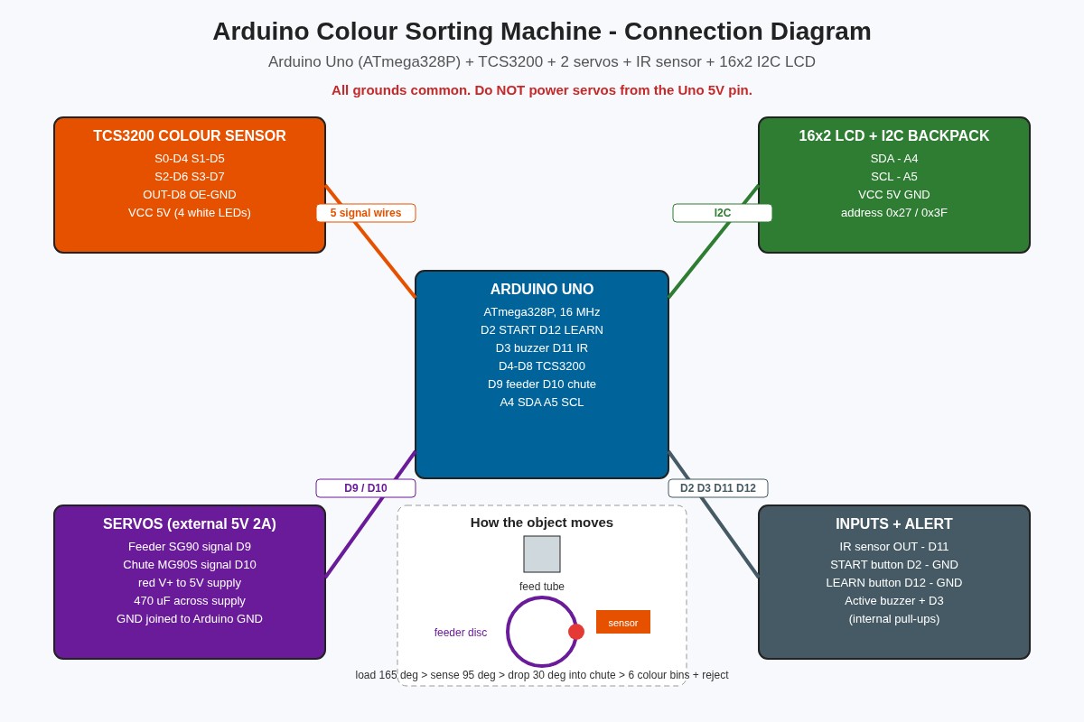
Arduino Colour Sorting Machine with TCS3200, Servo Chute, IR Feeder Check & 16×2 LCD Counter

Connection diagram of the Arduino Uno colour sorting machine with TCS3200 colour sensor, feeder and chute servos, IR sensor, buttons, buzzer and 16x2 I2C LCD

Build an Arduino Uno colour sorting machine that feeds objects one by one, reads their colour with a TCS3200 sensor, turns a servo chute to the right bin and counts every colour on a 16×2 LCD, with a learn mode and EEPROM memory.

  • DifficultyAdvanced
  • Build time5–8 hours
  • Board / MCUArduino Uno (ATmega328P)
  • Parts12 items
  • CodeArduino C++

Need it ready-made? Buy Ready Project

Sorting things by colour is a real job in factories: sweets, plastic pellets, pharmacy capsules, beads and even recycled bottle caps are sorted by machines that look at each piece and push it into the right bin. This Arduino colour sorting machine is a desktop version of that idea. You pour objects into a tube, and the machine takes them one at a time, checks the colour, and drops each one into its own cup while the LCD keeps count.

It is a complete combination project: a TCS3200 colour sensor, two servo motors working in sequence, an IR sensor that knows when the tube is empty, two buttons, a buzzer and a 16×2 I2C LCD, all controlled by one ATmega328P. You will learn how a colour sensor turns light into frequency, how to calibrate a sensor with white and black references, nearest-colour matching, smooth servo motion and saving data in EEPROM.

Connection diagram of the Arduino Uno colour sorting machine with TCS3200 colour sensor, feeder and chute servos, IR sensor, buttons, buzzer and 16x2 I2C LCD

How It Works

  • Feeding: the top servo turns a disc with one hole in it. At 165° the hole sits under the feed tube and one object falls in. The disc then turns slowly to 95°, which carries the object under the colour sensor.
  • Presence check: an IR obstacle sensor looks into the hole at the sensing position. If nothing is there, the tube is empty: the machine beeps, shows Tube empty? and pauses until you refill it and press START.
  • Reading the colour: the TCS3200 has an 8×8 grid of photodiodes with red, green, blue and clear filters. Pins S2 and S3 select the filter, and the OUT pin gives a square wave whose frequency rises with the amount of light. The Arduino measures the period of that wave with pulseIn() for each filter, averaging 8 readings.
  • Normalising: raw periods depend on distance and lighting, so the sketch maps each one between your black-card and white-card readings to a value from 0 to 255. This makes the numbers stable and easy to compare.
  • Matching: the reading is compared with six learned reference colours (red, orange, yellow, green, blue and brown) using the sum of the R, G and B differences. The closest colour wins. If even the closest one is more than 60 points away, the object goes to the reject bin.
  • Sorting: the bottom servo turns the chute to the angle for that colour (20° to 170°, seven positions), then the feeder disc turns to 30° and the object drops down the chute into its cup.
  • Counting and memory: each bin has a counter shown on the LCD and printed on the Serial Monitor. Counters and the learned colours are saved in EEPROM, so they are still there after power-off. A long press (2 s) on START resets the counters.

Components Required

  • Arduino Uno R3 or Nano (ATmega328P, 16 MHz) – 1
  • TCS3200 / TCS230 colour sensor module (with 4 white LEDs) – 1
  • SG90 micro servo for the feeder disc – 1
  • MG90S metal-gear servo for the chute – 1
  • IR obstacle sensor module (FC-51 or similar) – 1
  • 16×2 LCD with I2C backpack (PCF8574, address 0x27 or 0x3F) – 1
  • 5 V active buzzer – 1
  • 12 mm tactile push buttons (START and LEARN) – 2
  • 5 V 2 A power supply or LM2596 buck converter for the servos – 1
  • 470 µF 16 V electrolytic capacitor (across the servo supply) – 1
  • Breadboard or perfboard, jumper wires and a white/black calibration card – 1 set
  • Frame: 3 mm MDF, acrylic or 3D-printed parts, a 12 mm feed tube and 7 small cups – 1 set

Wiring Table

Module / pinArduino Uno pinNotes
TCS3200 VCC / GND5V / GNDModule also powers its 4 white LEDs
TCS3200 S0D4HIGH together with S1 LOW = 20 % output scaling
TCS3200 S1D5LOW
TCS3200 S2D6Filter select
TCS3200 S3D7Filter select
TCS3200 OUTD8Square-wave output measured with pulseIn()
TCS3200 OEGNDOutput enable (active LOW); some modules tie it already
Feeder servo SG90 signalD9Red to external 5 V, brown to common GND
Chute servo MG90S signalD10Red to external 5 V, brown to common GND
IR sensor OUTD11VCC 5V, GND; output LOW when an object is in front
START buttonD2Other leg to GND, internal pull-up
LEARN buttonD12Other leg to GND, internal pull-up
Active buzzer +D3Buzzer – to GND (use a buzzer under 30 mA)
LCD I2C SDA / SCLA4 / A5VCC 5V, GND
External 5 V 2 A supply (–)GNDMust be joined to the Arduino GND

Pin check: D9 and D10 both work for servos because the Servo library uses Timer1 on the Uno. That also disables analogWrite() on D9 and D10, which this project does not need. The on-board LED on D13 lights while the machine is running.

Connection Diagram

The diagram above shows how the modules connect to the Arduino and how an object moves through the machine. The drawing below lists every pin exactly as used in the code.

Arduino Colour Sorting Machine – Pin-Accurate Wiring Arduino Uno D2 START button → GND (internal pull-up) D3 Active buzzer (+), buzzer (–) → GND D4 TCS3200 S0 (frequency scale) D5 TCS3200 S1 D6 TCS3200 S2 (filter select) D7 TCS3200 S3 D8 TCS3200 OUT (square wave); OE → GND D9 Feeder servo SG90 signal (orange wire) D10 Chute servo MG90S signal (orange wire) D11 IR obstacle sensor OUT (LOW = object) D12 LEARN button → GND (internal pull-up) A4 / A5 LCD I2C SDA / SCL 5V VCC of TCS3200, IR sensor and LCD only GND Common GND: Uno, sensors, LCD AND servo supply (–) External 5 V 2 A supply (+) → red wire of both servos (–) → servo brown wires + Uno GND 470 µF across (+) and (–) Never power the two servos from the Uno 5V pin: the current spikes reset the board and spoil colour readings. Mount the TCS3200 about 10–15 mm above the feeder hole and shade it from room light with a black tube or box.
Pin-accurate connection diagram for the Arduino colour sorting machine.

Building the Mechanism

  • Feed tube: a 12–15 mm plastic tube or a rolled card tube, a little wider than your objects. Fix it vertically above the feeder disc.
  • Feeder disc: a 50 mm round disc (MDF, acrylic or 3D print) with one hole slightly bigger than one object, screwed to the SG90 horn. Under the disc, a fixed base plate has no hole except at the drop position (30°), so the object rides in the hole until it reaches the chute.
  • Sensor window: mount the TCS3200 looking down on the hole at 95°, 10–15 mm above it, inside a small black shroud so room light does not change the reading. Put the IR sensor at the side of the same position.
  • Chute: a 120 mm half pipe (cut PVC pipe or folded card) glued to the MG90S horn. Arrange 7 cups in a half circle under the end of the chute.
  • Tune the angles: adjust FEED_LOAD, FEED_SENSE, FEED_DROP and CHUTE_ANGLE[] at the top of the sketch to match your build.

Code

Install LiquidCrystal I2C (by Frank de Brabander) from the Library Manager. Servo, Wire and EEPROM come with the Arduino IDE. Select Arduino Uno (or Nano, ATmega328P) and upload. The sketch was compile-checked for the Uno: about 11 KB of flash and 870 bytes of RAM.

/*
  Arduino Colour Sorting Machine
  TCS3200 colour sensor + 2 servos + 16x2 I2C LCD + IR presence sensor + buzzer
  Board: Arduino Uno / Nano (ATmega328P, 16 MHz)
  Arduino Project Hub - ardiunoprojecthub.online - Project #68

  How it works:
   1. The feeder servo picks one object (bead, candy, small block) from the tube
      and carries it under the TCS3200 colour sensor.
   2. The sensor measures red, green, blue and clear light. The sketch compares
      the reading with six learned reference colours (nearest match).
   3. The chute servo turns to the bin for that colour, the feeder drops the
      object, and the LCD shows the colour and the count for each bin.
   4. Counts and learned colours are kept in EEPROM, so they survive power-off.

  Buttons (to GND, internal pull-ups):
   START (D2)  : short press = run / pause, long press (2 s) = reset counters
   LEARN (D12) : hold while powering up = learn mode (teach the 6 colours)
*/

#include <Wire.h>
#include <Servo.h>
#include <EEPROM.h>
#include <LiquidCrystal_I2C.h>

// ---------------- Pin map ----------------
const uint8_t PIN_START  = 2;   // start / pause button
const uint8_t PIN_BUZZER = 3;   // active buzzer (+)
const uint8_t PIN_S0     = 4;   // TCS3200 frequency scaling
const uint8_t PIN_S1     = 5;
const uint8_t PIN_S2     = 6;   // TCS3200 photodiode filter select
const uint8_t PIN_S3     = 7;
const uint8_t PIN_OUT    = 8;   // TCS3200 square-wave output
const uint8_t PIN_FEED   = 9;   // feeder (top) servo signal
const uint8_t PIN_CHUTE  = 10;  // chute (bottom) servo signal
const uint8_t PIN_IR     = 11;  // IR obstacle sensor OUT (LOW = object present)
const uint8_t PIN_LEARN  = 12;  // learn button
const uint8_t PIN_LED    = 13;  // status LED (on-board)

// ---------------- Mechanics (tune for your build) ----------------
const uint8_t FEED_LOAD   = 165;  // feeder hole under the tube
const uint8_t FEED_SENSE  = 95;   // feeder hole under the colour sensor
const uint8_t FEED_DROP   = 30;   // feeder hole over the chute
const uint8_t CHUTE_ANGLE[7] = {20, 45, 70, 95, 120, 145, 170}; // 6 colours + reject bin

// ---------------- Colour table ----------------
const uint8_t NUM_COLOURS = 6;
const char* const COLOUR_NAME[7] = {"Red", "Orange", "Yellow", "Green", "Blue", "Brown", "Reject"};
const uint8_t REJECT = 6;
const uint16_t MATCH_LIMIT = 60;   // larger distance than this = unknown colour

struct Rgb { uint16_t r, g, b; };  // normalised values 0..255 (higher = more of that colour)

// Typical defaults for a TCS3200 at 20% scaling, ~15 mm above the object.
// Run learn mode once for best results with your own lighting and objects.
Rgb ref[NUM_COLOURS] = {
  {190,  60,  70}, {200, 110,  60}, {200, 185,  80},
  { 80, 170,  90}, { 60, 110, 200}, {120,  90,  80}
};

uint16_t binCount[7] = {0};

// ---------------- EEPROM layout ----------------
const uint16_t EE_MAGIC_ADDR = 0;     // 2 bytes
const uint16_t EE_REF_ADDR   = 2;     // 6 x 6 bytes
const uint16_t EE_COUNT_ADDR = 40;    // 7 x 2 bytes
const uint16_t EE_MAGIC      = 0xC068;

LiquidCrystal_I2C lcd(0x27, 16, 2);   // change to 0x3F if your LCD stays blank
Servo feeder, chute;

bool running = false;
uint16_t whiteRef[3] = {0, 0, 0};     // period (us) under white card, for normalising
uint16_t blackRef[3] = {0, 0, 0};     // period (us) under black card

// ---------------- Helpers ----------------
void beep(uint16_t ms) {
  digitalWrite(PIN_BUZZER, HIGH);
  delay(ms);
  digitalWrite(PIN_BUZZER, LOW);
}

void lcdLine(uint8_t row, const char* text) {
  lcd.setCursor(0, row);
  uint8_t n = 0;
  while (text[n] && n < 16) { lcd.write(text[n]); n++; }
  while (n < 16) { lcd.write(' '); n++; }    // clear the rest of the row
}

// Wait for a button press and its release (with debounce). Returns press time in ms.
uint32_t waitPress(uint8_t pin) {
  while (digitalRead(pin) == HIGH) {}
  delay(25);
  uint32_t t0 = millis();
  while (digitalRead(pin) == LOW) {}
  delay(25);
  return millis() - t0;
}

// Move a servo slowly so the object does not jump out of the feeder hole.
void moveSlow(Servo &s, uint8_t target) {
  int pos = s.read();
  int step = (target > pos) ? 1 : -1;
  while (pos != target) {
    pos += step;
    s.write(pos);
    delay(6);
  }
}

// Read one filter channel: average period of the OUT square wave in microseconds.
// Lower period = more light of that colour.
uint16_t readPeriod(bool s2, bool s3) {
  digitalWrite(PIN_S2, s2);
  digitalWrite(PIN_S3, s3);
  delay(5);                                  // let the filter settle
  uint32_t sum = 0;
  uint8_t ok = 0;
  for (uint8_t i = 0; i < 8; i++) {
    uint32_t p = pulseIn(PIN_OUT, LOW, 20000UL);
    if (p > 0) { sum += p; ok++; }
  }
  if (ok == 0) return 0xFFFF;               // no signal: sensor not wired or too dark
  return (uint16_t)(sum / ok);
}

// Raw periods for red, green and blue filters
void readRaw(uint16_t raw[3]) {
  raw[0] = readPeriod(LOW, LOW);      // red filter
  raw[1] = readPeriod(HIGH, HIGH);    // green filter
  raw[2] = readPeriod(LOW, HIGH);     // blue filter
}

// Convert periods to 0..255 using the black and white calibration
Rgb readColour() {
  uint16_t raw[3];
  readRaw(raw);
  uint16_t v[3];
  for (uint8_t i = 0; i < 3; i++) {
    long x = map((long)raw[i], (long)blackRef[i], (long)whiteRef[i], 0L, 255L);
    v[i] = (uint16_t)constrain(x, 0L, 255L);
  }
  Rgb c = {v[0], v[1], v[2]};
  return c;
}

// Nearest reference colour (Manhattan distance). Returns REJECT if nothing is close.
uint8_t classify(const Rgb &c, uint16_t &bestDist) {
  uint8_t best = REJECT;
  bestDist = 0xFFFF;
  for (uint8_t i = 0; i < NUM_COLOURS; i++) {
    uint16_t d = abs((int)c.r - (int)ref[i].r) +
                 abs((int)c.g - (int)ref[i].g) +
                 abs((int)c.b - (int)ref[i].b);
    if (d < bestDist) { bestDist = d; best = i; }
  }
  if (bestDist > MATCH_LIMIT) best = REJECT;
  return best;
}

// ---------------- EEPROM ----------------
void saveCounts() {
  for (uint8_t i = 0; i < 7; i++) EEPROM.put(EE_COUNT_ADDR + i * 2, binCount[i]);
}

void saveRefs() {
  EEPROM.put(EE_MAGIC_ADDR, EE_MAGIC);
  for (uint8_t i = 0; i < NUM_COLOURS; i++) EEPROM.put(EE_REF_ADDR + i * 6, ref[i]);
  // black/white calibration stored after the colour table
  EEPROM.put(EE_REF_ADDR + 36 + 16, whiteRef);
  EEPROM.put(EE_REF_ADDR + 36 + 22, blackRef);
}

bool loadEeprom() {
  uint16_t magic;
  EEPROM.get(EE_MAGIC_ADDR, magic);
  if (magic != EE_MAGIC) return false;
  for (uint8_t i = 0; i < NUM_COLOURS; i++) EEPROM.get(EE_REF_ADDR + i * 6, ref[i]);
  for (uint8_t i = 0; i < 7; i++) {
    EEPROM.get(EE_COUNT_ADDR + i * 2, binCount[i]);
    if (binCount[i] == 0xFFFF) binCount[i] = 0;
  }
  EEPROM.get(EE_REF_ADDR + 36 + 16, whiteRef);
  EEPROM.get(EE_REF_ADDR + 36 + 22, blackRef);
  return true;
}

// ---------------- Learn mode ----------------
// Step 1: white card, step 2: black card, steps 3..8: one sample of each colour.
void learnMode() {
  char buf[17];
  moveSlow(feeder, FEED_SENSE);

  lcdLine(0, "LEARN: put WHITE");
  lcdLine(1, "card, press LRN");
  waitPress(PIN_LEARN);
  readRaw(whiteRef);
  beep(60);

  lcdLine(0, "LEARN: put BLACK");
  lcdLine(1, "card, press LRN");
  waitPress(PIN_LEARN);
  readRaw(blackRef);
  beep(60);

  for (uint8_t i = 0; i < NUM_COLOURS; i++) {
    snprintf(buf, sizeof(buf), "LEARN: %s", COLOUR_NAME[i]);
    lcdLine(0, buf);
    lcdLine(1, "place, press LRN");
    waitPress(PIN_LEARN);
    // average three readings for a stable reference
    uint32_t r = 0, g = 0, b = 0;
    for (uint8_t k = 0; k < 3; k++) {
      Rgb c = readColour();
      r += c.r; g += c.g; b += c.b;
    }
    ref[i].r = r / 3; ref[i].g = g / 3; ref[i].b = b / 3;
    snprintf(buf, sizeof(buf), "R%3u G%3u B%3u", ref[i].r, ref[i].g, ref[i].b);
    lcdLine(1, buf);
    beep(60);
    delay(800);
  }
  saveRefs();
  lcdLine(0, "Colours saved!");
  lcdLine(1, "Press START");
  beep(200);
}

// ---------------- Display ----------------
void showIdle() {
  char buf[17];
  uint16_t total = 0;
  for (uint8_t i = 0; i < 7; i++) total += binCount[i];
  lcdLine(0, running ? "RUNNING" : "PAUSED - START");
  snprintf(buf, sizeof(buf), "Total sorted %u", total);
  lcdLine(1, buf);
}

// ---------------- Sort one object ----------------
void sortOne() {
  char buf[17];

  // 1. pick up an object from the tube
  moveSlow(feeder, FEED_LOAD);
  delay(400);

  // 2. carry it under the sensor
  moveSlow(feeder, FEED_SENSE);
  delay(300);

  // 3. is there really an object? (IR sensor looks into the feeder hole)
  if (digitalRead(PIN_IR) == HIGH) {
    lcdLine(0, "Tube empty?");
    lcdLine(1, "Refill & START");
    beep(400);
    running = false;
    return;
  }

  // 4. read and classify the colour
  Rgb c = readColour();
  uint16_t dist;
  uint8_t bin = classify(c, dist);

  snprintf(buf, sizeof(buf), "%-7s d=%u", COLOUR_NAME[bin], dist);
  lcdLine(0, buf);
  snprintf(buf, sizeof(buf), "R%3u G%3u B%3u", c.r, c.g, c.b);
  lcdLine(1, buf);

  Serial.print(F("RGB "));
  Serial.print(c.r); Serial.print(' ');
  Serial.print(c.g); Serial.print(' ');
  Serial.print(c.b);
  Serial.print(F(" -> "));
  Serial.println(COLOUR_NAME[bin]);

  // 5. turn the chute, then drop the object
  moveSlow(chute, CHUTE_ANGLE[bin]);
  delay(150);
  moveSlow(feeder, FEED_DROP);
  delay(350);

  binCount[bin]++;
  saveCounts();                // EEPROM.put only writes bytes that changed
  if (bin == REJECT) beep(150);

  snprintf(buf, sizeof(buf), "%s bin: %u", COLOUR_NAME[bin], binCount[bin]);
  lcdLine(1, buf);
}

// ---------------- Setup / loop ----------------
void setup() {
  Serial.begin(9600);
  pinMode(PIN_START, INPUT_PULLUP);
  pinMode(PIN_LEARN, INPUT_PULLUP);
  pinMode(PIN_IR, INPUT);
  pinMode(PIN_BUZZER, OUTPUT);
  pinMode(PIN_LED, OUTPUT);
  pinMode(PIN_S0, OUTPUT); pinMode(PIN_S1, OUTPUT);
  pinMode(PIN_S2, OUTPUT); pinMode(PIN_S3, OUTPUT);
  pinMode(PIN_OUT, INPUT);
  digitalWrite(PIN_S0, HIGH);  // 20% output frequency scaling (S0=H, S1=L)
  digitalWrite(PIN_S1, LOW);

  lcd.init();
  lcd.backlight();

  feeder.attach(PIN_FEED);
  chute.attach(PIN_CHUTE);
  feeder.write(FEED_SENSE);
  chute.write(CHUTE_ANGLE[3]);

  bool haveData = loadEeprom();
  if (!haveData) {
    // first power-up: sensible default periods (white ~ 40 us, black ~ 400 us)
    for (uint8_t i = 0; i < 3; i++) { whiteRef[i] = 40; blackRef[i] = 400; }
    for (uint8_t i = 0; i < 7; i++) binCount[i] = 0;
    saveRefs();            // write defaults so counts are kept from now on
    saveCounts();
  }

  lcdLine(0, "Colour Sorter");
  lcdLine(1, haveData ? "Data loaded" : "Defaults - LEARN");
  beep(80);
  delay(1200);

  if (digitalRead(PIN_LEARN) == LOW) {   // LEARN held at power-up
    while (digitalRead(PIN_LEARN) == LOW) {}
    delay(50);
    learnMode();
  }
  showIdle();
}

void loop() {
  // START button: short press toggles run/pause, long press resets the counters
  if (digitalRead(PIN_START) == LOW) {
    uint32_t held = waitPress(PIN_START);
    if (held > 2000) {
      for (uint8_t i = 0; i < 7; i++) binCount[i] = 0;
      saveCounts();
      running = false;
      lcdLine(0, "Counters reset");
      beep(300);
      delay(1000);
    } else {
      running = !running;
      beep(40);
    }
    showIdle();
  }

  digitalWrite(PIN_LED, running);
  if (running) {
    sortOne();
    if (!running) showIdle();
  }
}

Calibration and Testing

  • Learn mode: hold the LEARN button while you power up (or press reset), then release it. The LCD asks for a white card, then a black card, then one sample of each of the six colours. Place each one in the feeder hole under the sensor and press LEARN. The values are saved in EEPROM.
  • Check readings: open the Serial Monitor at 9600 baud. Each sorted object prints a line like RGB 192 64 71 -> Red. If two colours give very similar numbers (for example orange and brown), run learn mode again with better shading.
  • Run: press START to begin. The LED on D13 lights and the machine sorts about one object every 2–3 seconds. Press START again to pause; hold it for 2 seconds to reset the counters.
  • Tune the reject limit: raise MATCH_LIMIT if too many good objects go to reject, lower it if wrong colours slip into a bin.

Troubleshooting

ProblemFix
LCD backlight is on but no textTurn the blue contrast pot on the I2C backpack. If still blank, change the address in the sketch from 0x27 to 0x3F.
Arduino resets when the servos moveThe servos are drawing current from the Uno. Power them from a separate 5 V 2 A supply, join the grounds and add the 470 µF capacitor.
All readings are 0 or 255OUT is not reaching D8 or OE is not tied to GND. Check S0 to S3 wiring and that the four white LEDs on the module are lit.
Colour changes with room lightShade the sensor with a black tube or box and run learn mode again in the same lighting.
Every object goes to rejectLearn mode was skipped and the defaults do not match your objects. Hold LEARN at power-up and teach all six colours.
Machine says Tube empty? with objects presentAdjust the IR sensor’s blue trim pot until its LED turns on only when an object is in the hole. Matt black objects may need the sensor moved closer.
Objects jam between disc and baseMake the hole 1–2 mm bigger than the object and sand the edges. The slow servo movement in the code also helps.
Chute misses the cupsChange the values in CHUTE_ANGLE[] in 5° steps until each object lands in the middle of its cup.

Ideas to Extend

  • Add an HC-05 Bluetooth module to send the counts to a phone.
  • Replace the SG90 feeder with a small stepper motor for faster, more precise feeding.
  • Add a seventh learned colour (purple or white) by using the reject position as a real bin.

Arduino Nano Every Fridge Door Alarm with Reed Switch, Buzzer & Delay Knob

Arduino Nano Every fridge door alarm on a breadboard with reed switch and magnet on a fridge door, active buzzer with 2N2222, green and red LEDs, MUTE button and 10k potentiometer

Build a simple fridge door alarm with an Arduino Nano Every (ATmega4809) and a magnetic reed switch: it beeps when the fridge door is left open, gets louder after a while, has an adjustable delay knob and a 60-second mute button.

  • DifficultyEasy
  • Build time1–2 hours
  • Board / MCUArduino Nano Every (ATmega4809)
  • Parts10 items
  • CodeArduino C++

Need it ready-made? Buy Ready Project

Leaving the fridge door slightly open wastes electricity, makes the compressor work harder and spoils food. This Arduino Nano Every fridge door alarm fixes that with a tiny, low-cost circuit. A magnetic reed switch is stuck to the fridge body and a small magnet to the door. When the door opens, the magnet moves away, the switch opens and the ATmega4809 starts a timer. If the door is still open after the delay you set with a knob, a buzzer starts beeping.

It is a great small project for beginners: you learn digital inputs with internal pull-ups, debouncing, non-blocking timing with millis(), reading a potentiometer and driving a buzzer through a transistor. The same circuit works for a freezer, a cupboard, a main door or a cash drawer.

Arduino Nano Every fridge door alarm on a breadboard with reed switch and magnet on a fridge door, active buzzer with 2N2222, green and red LEDs, MUTE button and 10k potentiometer

How It Works

  • Door sensing (D2): the reed switch is wired between D2 and GND with the internal pull-up turned on. With the magnet close, the switch is closed and D2 reads LOW (door closed). When the door opens, the switch opens and D2 goes HIGH.
  • Debouncing: a change on D2 is accepted only after it stays the same for 50 ms, so door bumps and contact bounce do not cause false beeps.
  • Adjustable delay (A0): the 10 kΩ pot sets the allowed open time from 10 to 120 seconds. The code maps the 0–1023 reading to this range every loop, so you can turn the knob at any time.
  • Two alarm levels: while the door is open but within the delay, the red LED stays on. After the delay, the buzzer gives a short beep every second (WARNING). After twice the delay it beeps fast, five times per second (ALARM), so it is hard to ignore.
  • Mute button (D3): pressing it while the door is open silences the buzzer for 60 seconds, handy when you are loading groceries. The LEDs keep blinking to remind you.
  • Auto reset: closing the door switches the buzzer off, turns the green LED on and clears the mute timer, ready for the next opening.
  • Non-blocking code: everything runs on millis() with no long delay() calls, so the button and the door are checked hundreds of times per second.

Components Required

  • Arduino Nano Every (ATmega4809) – 1
  • Magnetic reed switch (door sensor, normally open) with magnet – 1
  • Active buzzer 5V – 1
  • 2N2222 (or BC547) NPN transistor + 1 kΩ base resistor – 1 set
  • Green and red 5 mm LEDs with 220 Ω resistors – 1 each
  • Tactile push button (MUTE) – 1
  • 10 kΩ potentiometer (delay knob) – 1
  • 5V USB adapter or USB power bank with micro-USB cable – 1
  • Small breadboard or perfboard, jumper wires and 2-core wire for the door – 1 set
  • Double-sided tape for the reed switch and magnet – 1

Wiring Table

Part / pinNano Every pinNotes
Reed switch leg 1D2Internal pull-up in code, no resistor needed
Reed switch leg 2GNDUse thin 2-core wire along the door seal
MUTE buttonD3 and GNDInternal pull-up
Green LED anodeD5 through 220 ΩCathode to GND – lit when door is closed
Red LED anodeD6 through 220 ΩCathode to GND – lit/blinking when door is open
2N2222 baseD9 through 1 kΩEmitter to GND
Active buzzer+ to 5V, – to 2N2222 collectorThe transistor lets a louder buzzer run without loading the pin
10 kΩ potEnds to 5V and GND, wiper to A0Turn right for a longer delay
PowerUSB connector5V USB adapter or power bank

Mounting tip: fix the reed switch on the fridge body near the handle side and the magnet on the door so they are within 10 mm of each other when the door is shut. Keep the main board outside the fridge, on top or on the side.

Connection Diagram

The illustration above shows the parts laid out on a breadboard. It is a layout guide only, so follow the pin-accurate drawing below, which matches the wiring table.

Arduino Nano Every Fridge Door Alarm – Pin-Accurate Wiring Nano Every 5V Pot left end; buzzer + pin GND Reed, button, LED cathodes, emitter, pot right end D2 Reed switch (other leg to GND) D3 MUTE button (other leg to GND) D5 220 Ω to green LED (door closed) D6 220 Ω to red LED (door open) D9 1 kΩ to 2N2222 base; buzzer – on collector A0 10 kΩ pot wiper (10–120 s delay) Power the Nano Every from a 5V USB adapter. Reed switch closed (magnet near) = door closed.
Pin-accurate connection diagram for the Arduino Nano Every fridge door alarm.

Code

In the Arduino IDE open Boards Manager, install Arduino megaAVR Boards, then select Tools → Board → Arduino Nano Every and keep Registers emulation at its default. No extra libraries are needed. The sketch uses about 4 KB of flash.

/*
  Arduino Nano Every (ATmega4809) Fridge Door Alarm
  Arduino Project Hub - ardiunoprojecthub.online

  Reed switch + magnet on the fridge door. If the door stays open
  longer than OPEN_WARN_MS the buzzer beeps slowly; after
  OPEN_ALARM_MS it beeps fast. The MUTE button silences the
  buzzer for SNOOZE_MS. Closing the door resets everything.

  Wiring:
    Reed switch  : D2 and GND (internal pull-up, LOW = door closed)
    MUTE button  : D3 and GND (internal pull-up)
    Active buzzer: D9 -> 1k -> 2N2222 base (buzzer on collector)
    Green LED    : D5 -> 220R -> LED -> GND (door closed)
    Red LED      : D6 -> 220R -> LED -> GND (door open)
    Delay pot    : 10k pot, ends on 5V/GND, wiper on A0 (10-120 s)
*/

const uint8_t PIN_REED   = 2;
const uint8_t PIN_MUTE   = 3;
const uint8_t PIN_GREEN  = 5;
const uint8_t PIN_RED    = 6;
const uint8_t PIN_BUZZER = 9;
const uint8_t PIN_POT    = A0;

const unsigned long DEBOUNCE_MS = 50;      // reed/button debounce time
const unsigned long SNOOZE_MS   = 60000UL; // mute time after button press
const unsigned long MIN_WARN_S  = 10;      // pot fully left
const unsigned long MAX_WARN_S  = 120;     // pot fully right

bool doorOpen = false;            // debounced door state
bool lastRawReed = false;
unsigned long reedChangedAt = 0;
unsigned long openedAt = 0;       // when the door was opened
unsigned long mutedUntil = 0;     // buzzer silent until this time
bool lastMute = HIGH;
unsigned long muteChangedAt = 0;

// Read the delay pot and turn it into a warning time in milliseconds
unsigned long warnDelayMs() {
  int raw = analogRead(PIN_POT);                       // 0..1023
  unsigned long s = MIN_WARN_S + (unsigned long)raw * (MAX_WARN_S - MIN_WARN_S) / 1023UL;
  return s * 1000UL;
}

void setup() {
  pinMode(PIN_REED, INPUT_PULLUP);
  pinMode(PIN_MUTE, INPUT_PULLUP);
  pinMode(PIN_GREEN, OUTPUT);
  pinMode(PIN_RED, OUTPUT);
  pinMode(PIN_BUZZER, OUTPUT);
  Serial.begin(9600);

  // Short start-up beep and LED test
  digitalWrite(PIN_GREEN, HIGH);
  digitalWrite(PIN_RED, HIGH);
  digitalWrite(PIN_BUZZER, HIGH);
  delay(150);
  digitalWrite(PIN_BUZZER, LOW);
  digitalWrite(PIN_RED, LOW);

  lastRawReed = (digitalRead(PIN_REED) == HIGH);   // HIGH = magnet away = open
  doorOpen = lastRawReed;
  openedAt = millis();
  Serial.println(F("Fridge door alarm ready"));
}

void loop() {
  unsigned long now = millis();

  // ---- Debounce the reed switch ----
  bool rawOpen = (digitalRead(PIN_REED) == HIGH);
  if (rawOpen != lastRawReed) {
    lastRawReed = rawOpen;
    reedChangedAt = now;
  }
  if ((now - reedChangedAt) > DEBOUNCE_MS && rawOpen != doorOpen) {
    doorOpen = rawOpen;
    if (doorOpen) {
      openedAt = now;
      Serial.println(F("Door OPEN"));
    } else {
      mutedUntil = 0;                       // reset snooze when closed
      Serial.println(F("Door CLOSED"));
    }
  }

  // ---- MUTE button (falling edge) ----
  bool mute = digitalRead(PIN_MUTE);
  if (mute != lastMute && (now - muteChangedAt) > DEBOUNCE_MS) {
    muteChangedAt = now;
    lastMute = mute;
    if (mute == LOW && doorOpen) {
      mutedUntil = now + SNOOZE_MS;
      Serial.println(F("Buzzer muted for 60 s"));
    }
  }

  // ---- LEDs and buzzer ----
  if (!doorOpen) {
    digitalWrite(PIN_GREEN, HIGH);
    digitalWrite(PIN_RED, LOW);
    digitalWrite(PIN_BUZZER, LOW);
    return;
  }

  digitalWrite(PIN_GREEN, LOW);
  unsigned long openFor = now - openedAt;
  unsigned long warnMs = warnDelayMs();
  bool muted = (mutedUntil != 0) && ((long)(mutedUntil - now) > 0);

  if (openFor < warnMs) {
    digitalWrite(PIN_RED, HIGH);            // open, still OK
    digitalWrite(PIN_BUZZER, LOW);
  } else if (openFor < warnMs * 2) {
    // WARNING: slow beep (150 ms every second), red LED blinks
    bool on = (openFor % 1000UL) < 150;
    digitalWrite(PIN_RED, (openFor % 1000UL) < 500);
    digitalWrite(PIN_BUZZER, (on && !muted) ? HIGH : LOW);
  } else {
    // ALARM: fast beep (100 ms on / 100 ms off), red LED fast blink
    bool on = (openFor % 200UL) < 100;
    digitalWrite(PIN_RED, on);
    digitalWrite(PIN_BUZZER, (on && !muted) ? HIGH : LOW);
  }
}

Testing

  • Open the Serial Monitor at 9600 baud. Move the magnet away from the reed switch: you should see Door OPEN and the red LED turns on.
  • Turn the pot fully left (10 s). Keep the magnet away: after 10 s the slow beep starts, after 20 s the fast beep starts.
  • Press MUTE: the buzzer stops for 60 seconds but the red LED keeps blinking.
  • Bring the magnet back: Door CLOSED appears, the buzzer stops and the green LED lights. Now set the pot to the delay you want, for example 30–60 seconds.

Troubleshooting

ProblemFix
Alarm says open even when the door is shutThe magnet is too far from the reed switch. Move them closer (under 10 mm) or use a stronger magnet. Check the switch type is normally open.
Buzzer never soundsCheck the transistor pins (E-B-C), the 1 kΩ base resistor and that the buzzer is an active type with + on 5V.
Random beeps when the door is closedLong door wires pick up noise. Twist the two wires, keep them away from the compressor cable, or add a 100 nF capacitor from D2 to GND.
Delay does not change with the knobCheck the pot wiper goes to A0 and the outer pins go to 5V and GND.
Upload fails on the Nano EverySelect Arduino Nano Every in the board menu, choose the right COM port and use a data USB cable, not a charge-only one.
MUTE button does nothingIt only works while the door is open. Check the button goes between D3 and GND on opposite legs.

Ideas to Extend

  • Add a DS18B20 sensor inside the fridge and beep if the temperature rises above 8 °C.
  • Count how many times the door is opened per day and store it in EEPROM.
  • Swap the Nano Every for a Wemos D1 Mini to get a phone notification when the door is left open.

Arduino Breathalyzer with MQ-3 Alcohol Sensor, I2C LCD & Buzzer

Arduino Uno breathalyzer on a breadboard with MQ-3 alcohol sensor module, green, yellow and red LEDs, active buzzer, push button and 16x2 I2C LCD showing CLEAR

Build an Arduino breathalyzer with an MQ-3 alcohol sensor that warms up, calibrates itself in clean air, runs a 5-second blow test and shows CLEAR, LOW or HIGH on a 16×2 I2C LCD with LEDs and a buzzer.

  • DifficultyMedium
  • Build time2–3 hours
  • Board / MCUArduino Uno (ATmega328P)
  • Parts10 items
  • CodeArduino C++

Need it ready-made? Buy Ready Project

This Arduino breathalyzer uses the MQ-3 alcohol sensor to detect ethanol vapour in a breath sample. After a 60-second heater warm-up it learns the clean-air reading by itself, then you press a button and blow for 5 seconds. The Arduino records the peak reading, compares it with the clean-air baseline and shows CLEAR, ALCOHOL LOW or ALCOHOL HIGH on a 16×2 I2C LCD, lights a green, yellow or red LED and beeps a matching pattern.

It is a great medium-level project to learn analog sensors, averaging and noise filtering, auto-calibration, peak detection and I2C displays. Important: this is an educational vapour indicator, not a certified breath alcohol tester. Its readings change with temperature, humidity and sensor age, so never use it to decide whether anyone is fit to drive.

Arduino Uno breathalyzer on a breadboard with MQ-3 alcohol sensor module, green, yellow and red LEDs, active buzzer, push button and 16x2 I2C LCD showing CLEAR

How It Works

  • MQ-3 sensor: inside the metal mesh is a tin dioxide (SnO2) element with a small heater. When alcohol vapour reaches the hot surface its resistance drops, so the voltage on the module’s AOUT pin rises. The Arduino reads it on A0 as a number from 0 to 1023.
  • Warm-up: the heater needs time to reach a stable temperature, so the LCD counts down 60 seconds with the yellow LED on. A brand-new sensor should be powered for 24–48 hours once (burn-in) before readings settle.
  • Auto-calibration: the sketch averages 500 readings in clean air and stores that as the baseline. Every result is shown as a rise above this baseline, so the project works even though every MQ-3 module reads a little differently.
  • Blow test: press the button, wait for the beep and blow steadily for 5 seconds from about 2–3 cm away. The yellow LED blinks while the Arduino samples and keeps the highest reading (the peak).
  • Result: a rise under 60 counts is CLEAR (green, one short beep), 60–199 is LOW (yellow, two beeps) and 200 or more is HIGH (red, five beeps). A 0–100% level bar value is also shown. The thresholds are constants at the top of the code, so you can tune them.
  • Recovery: after a test the sensor needs a few seconds to clear. The sketch waits until the reading falls back near the baseline before it shows Ready again, so a second test is not falsely high.

Components Required

  • Arduino Uno R3 (or Nano, ATmega328P) – 1
  • MQ-3 alcohol sensor module (with AOUT pin) – 1
  • 16×2 LCD with I2C backpack (PCF8574, address 0x27 or 0x3F) – 1
  • Green, yellow and red 5 mm LEDs – 1 each
  • 220 Ω resistors – 3
  • Active buzzer 5V – 1
  • Tactile push button 12 mm – 1
  • Half-size breadboard – 1
  • Jumper wires (male-to-male and male-to-female) – 15
  • USB cable or 9V 1A adapter (MQ-3 heater draws about 150 mA) – 1

Wiring Table

Part / pinArduino pinNotes
MQ-3 VCC5VHeater needs a full 5V; 3.3V will not work
MQ-3 GNDGND
MQ-3 AOUTA0Analog output; DOUT pin is not used
LCD I2C VCC / GND5V / GND
LCD I2C SDAA4On the Uno R3 SDA is also next to AREF
LCD I2C SCLA5
Push buttonD2 and GNDInternal pull-up, no resistor needed
Green LED (via 220 Ω)D5Cathode (short leg) to GND
Yellow LED (via 220 Ω)D6Cathode to GND
Red LED (via 220 Ω)D7Cathode to GND
Active buzzer + / –D8 / GNDUse an active (self-oscillating) buzzer

Connection Diagram

The illustration above shows the parts laid out on the breadboard. It is a layout guide only, so follow the pin-accurate drawing below, which matches the wiring table.

Arduino MQ-3 Breathalyzer – Pin-Accurate Wiring Arduino Uno 5V MQ-3 VCC and LCD VCC (5V rail) GND GND rail: MQ-3, LCD, button, LEDs, buzzer A0 MQ-3 module AOUT (analog output) A4 (SDA) I2C LCD SDA A5 (SCL) I2C LCD SCL D2 Push button to GND (internal pull-up) D5 220 Ω to green LED anode, cathode to GND D6 220 Ω to yellow LED anode, cathode to GND D7 220 Ω to red LED anode, cathode to GND D8 Active buzzer +, buzzer – to GND
Pin-accurate connection diagram for the Arduino MQ-3 breathalyzer.

Code

In the Arduino IDE open Library Manager and install LiquidCrystal I2C (by Frank de Brabander). Select Arduino Uno as the board, paste the sketch and upload. Open the Serial Monitor at 9600 baud to see the baseline and each test result.

/*
  Arduino Breathalyzer with MQ-3 Alcohol Sensor, I2C LCD & Buzzer
  Arduino Project Hub - ardiunoprojecthub.online

  Educational alcohol-vapour indicator. NOT a legal or medical breath test:
  never use it to decide whether someone is fit to drive.

  Wiring:
    MQ-3 module  VCC -> 5V, GND -> GND, AOUT -> A0
    I2C LCD 16x2 VCC -> 5V, GND -> GND, SDA -> A4, SCL -> A5
    Push button  D2 -> GND (internal pull-up)
    Green LED    D5 -> 220R -> GND
    Yellow LED   D6 -> 220R -> GND
    Red LED      D7 -> 220R -> GND
    Active buzzer + -> D8, - -> GND
*/
#include <Wire.h>
#include <LiquidCrystal_I2C.h>

const uint8_t PIN_MQ3    = A0;
const uint8_t PIN_BTN    = 2;
const uint8_t PIN_GREEN  = 5;
const uint8_t PIN_YELLOW = 6;
const uint8_t PIN_RED    = 7;
const uint8_t PIN_BUZZ   = 8;

const uint16_t WARMUP_S     = 60;    // heater warm-up time (longer on first use)
const uint16_t BLOW_MS      = 5000;  // how long the user blows
const int      LOW_DELTA    = 60;    // ADC rise above baseline for "LOW"
const int      HIGH_DELTA   = 200;   // ADC rise above baseline for "HIGH"

LiquidCrystal_I2C lcd(0x27, 16, 2);  // change to 0x3F if the screen stays blank
int baseline = 0;

int readAvg(uint8_t n) {             // average n readings to reduce noise
  long sum = 0;
  for (uint8_t i = 0; i < n; i++) { sum += analogRead(PIN_MQ3); delay(5); }
  return sum / n;
}

void setLeds(bool g, bool y, bool r) {
  digitalWrite(PIN_GREEN, g);
  digitalWrite(PIN_YELLOW, y);
  digitalWrite(PIN_RED, r);
}

void beep(uint8_t times, uint16_t onMs) {
  for (uint8_t i = 0; i < times; i++) {
    digitalWrite(PIN_BUZZ, HIGH); delay(onMs);
    digitalWrite(PIN_BUZZ, LOW);  delay(onMs);
  }
}

void calibrate() {                   // learn the clean-air reading
  lcd.clear();
  lcd.print("Calibrating...");
  lcd.setCursor(0, 1);
  lcd.print("Keep clean air");
  long sum = 0;
  for (uint8_t i = 0; i < 50; i++) { sum += readAvg(10); delay(40); }
  baseline = sum / 50;
  Serial.print(F("Baseline ADC: "));
  Serial.println(baseline);
}

void warmUp() {
  setLeds(false, true, false);
  for (int s = WARMUP_S; s > 0; s--) {
    lcd.setCursor(0, 0);
    lcd.print("Sensor warm-up  ");
    lcd.setCursor(0, 1);
    lcd.print("Wait ");
    lcd.print(s);
    lcd.print(" s       ");
    delay(1000);
  }
}

void showReady() {
  setLeds(true, false, false);
  lcd.clear();
  lcd.print("Ready. Press btn");
  lcd.setCursor(0, 1);
  lcd.print("Base: ");
  lcd.print(baseline);
}

void runTest() {
  lcd.clear();
  lcd.print("Blow steadily");
  beep(1, 150);
  int peak = 0;
  unsigned long start = millis();
  while (millis() - start < BLOW_MS) {
    int v = readAvg(5);
    if (v > peak) peak = v;
    uint8_t left = (BLOW_MS - (millis() - start)) / 1000 + 1;
    lcd.setCursor(0, 1);
    lcd.print("ADC ");
    lcd.print(v);
    lcd.print("  ");
    lcd.print(left);
    lcd.print("s   ");
    setLeds(false, (millis() / 250) % 2, false);   // blink yellow while sampling
  }

  int delta = peak - baseline;
  if (delta < 0) delta = 0;
  uint8_t percent = constrain(map(delta, 0, 600, 0, 100), 0, 100);

  lcd.clear();
  lcd.print("Peak ");
  lcd.print(peak);
  lcd.print(" (+");
  lcd.print(delta);
  lcd.print(")");
  lcd.setCursor(0, 1);
  if (delta < LOW_DELTA) {
    lcd.print("CLEAR       ");
    setLeds(true, false, false);
    beep(1, 80);
  } else if (delta < HIGH_DELTA) {
    lcd.print("ALCOHOL LOW ");
    setLeds(false, true, false);
    beep(2, 150);
  } else {
    lcd.print("ALCOHOL HIGH");
    setLeds(false, false, true);
    beep(5, 200);
  }
  lcd.setCursor(12, 1);
  if (percent < 100) lcd.print(" ");
  if (percent < 10) lcd.print(" ");
  lcd.print(percent);
  lcd.print("%");

  Serial.print(F("Peak: ")); Serial.print(peak);
  Serial.print(F("  Delta: ")); Serial.print(delta);
  Serial.print(F("  Level: ")); Serial.print(percent); Serial.println(F("%"));

  delay(4000);
  // wait until the sensor has recovered close to baseline before the next test
  lcd.clear();
  lcd.print("Clearing sensor");
  while (readAvg(10) > baseline + LOW_DELTA / 2) {
    lcd.setCursor(0, 1);
    lcd.print("ADC ");
    lcd.print(readAvg(10));
    lcd.print("     ");
    delay(500);
  }
  showReady();
}

void setup() {
  Serial.begin(9600);
  pinMode(PIN_BTN, INPUT_PULLUP);
  pinMode(PIN_GREEN, OUTPUT);
  pinMode(PIN_YELLOW, OUTPUT);
  pinMode(PIN_RED, OUTPUT);
  pinMode(PIN_BUZZ, OUTPUT);

  lcd.init();
  lcd.backlight();
  lcd.print("MQ-3 Breath Test");
  lcd.setCursor(0, 1);
  lcd.print("Project Hub");
  delay(1500);

  warmUp();
  calibrate();
  showReady();
}

void loop() {
  if (digitalRead(PIN_BTN) == LOW) {         // button pressed
    delay(30);                               // debounce
    if (digitalRead(PIN_BTN) == LOW) {
      while (digitalRead(PIN_BTN) == LOW) {} // wait for release
      runTest();
    }
  }
}

Testing and Calibration

  • Power the circuit in clean air, away from perfume, hand sanitiser and cooking fumes. The LCD counts down the warm-up and then shows Ready with the baseline value (typically 100–300).
  • Press the button and blow normally. With clean breath the result should be CLEAR.
  • To test the alarm safely, rub a little hand sanitiser on a cotton bud and hold it about 2 cm from the sensor during the 5-second test. The reading should rise to LOW or HIGH.
  • If results feel too sensitive or not sensitive enough, change LOW_DELTA and HIGH_DELTA. You can also turn the small potentiometer on the module, which changes its load resistance, then restart so it recalibrates.

Troubleshooting

ProblemFix
LCD backlight on but no textTurn the blue contrast pot on the I2C backpack. If still blank, change the address in the code from 0x27 to 0x3F (run an I2C scanner to check).
Baseline keeps rising for minutesThe sensor is still warming. Let a new MQ-3 burn in for 24–48 hours once, or increase WARMUP_S to 180.
Always shows ALCOHOL HIGHIt calibrated in dirty air (sanitiser, perfume nearby). Move to fresh air and press reset to recalibrate.
Reading never changesCheck AOUT goes to A0, not DOUT. The sensor should feel warm after a minute; if not, check 5V and GND.
Arduino resets or LCD flickersThe heater draws about 150 mA. Use a good USB port or a 9V 1A adapter instead of a weak power bank.
Stuck on Clearing sensorWave fresh air over the sensor. If the room air changed, press reset to take a new baseline.

Ideas to Extend

  • Add a DHT22 sensor and correct the reading for temperature and humidity.
  • Store the last 10 results in the ATmega328P EEPROM and show them with a second button.
  • Replace the Uno with an ESP32 to log readings to a phone over Wi-Fi.

ATmega1284P Fingerprint Door Lock with R307, Keypad, OLED & Relay

ATmega1284P fingerprint door lock on a breadboard with R307 fingerprint sensor, 4x4 keypad, OLED display, relay module, solenoid lock, exit button, buzzer and LEDs

Build an ATmega1284P fingerprint door lock that opens with a stored fingerprint or a 6-digit keypad PIN, shows status on an OLED and drives a 12V solenoid lock through a relay.

  • DifficultyAdvanced
  • Build time5–8 hours
  • Board / MCUATmega1284P (16 MHz, MightyCore)
  • Parts15 items
  • CodeArduino C++

Need it ready-made? Buy Ready Project

This ATmega1284P fingerprint door lock is a complete access-control system for a home, lab or office door. It opens with any enrolled fingerprint or with a 6-digit PIN typed on a 4×4 keypad, then drives a 12V solenoid lock through a relay for five seconds and locks again by itself.

It combines several modules in one build: an R307 optical fingerprint sensor, a keypad, an OLED status screen, a relay, a reed sensor that warns when the door is left open, an inside exit button, a buzzer and two status LEDs. The ATmega1284P is a good fit because it has two hardware UARTs (one for the fingerprint sensor and one free for debugging), 128 KB of flash and 16 KB of RAM, all in a breadboard-friendly 40-pin DIP package.

ATmega1284P fingerprint door lock on a breadboard with R307 fingerprint sensor, 4x4 keypad, OLED display, relay module, solenoid lock, exit button, buzzer and LEDs

How It Works

  • Fingerprint check: the loop keeps asking the R307 for an image. When a finger is placed, the sensor turns it into a template and searches its own on-board library (up to 127 prints in this code). A match with a confidence score of 50 or more unlocks the door and the OLED shows which ID opened it.
  • PIN entry: digits typed on the keypad show as stars. # confirms and * clears. The PIN is kept in the chip’s EEPROM, so it survives power cuts. The first-boot PIN is 123456, so change it straight away.
  • Admin menu: A enrolls a new finger (two scans of the same finger), B deletes a stored ID, C changes the PIN and D shows how many prints are stored. A, B and C all ask for the current PIN first.
  • Lockout: three wrong fingers or PINs in a row lock the keypad and sensor for 30 seconds with a long beep, which slows down guessing.
  • Relay and auto re-lock: PB0 switches the relay, which feeds 12V to the solenoid for 5 seconds. A 1N4007 diode across the coil absorbs the voltage spike when it switches off.
  • Exit button and door sensor: the inside exit button always opens the door, even during lockout. The reed switch reads HIGH when the door is open, and if it stays open for more than 30 seconds the buzzer beeps and the OLED asks you to close it.

Components Required

  • ATmega1284P (40-pin DIP) microcontroller – 1
  • 16 MHz crystal with two 22 pF capacitors – 1 set
  • R307 or AS608 optical fingerprint sensor module – 1
  • 4×4 membrane keypad – 1
  • 0.96 inch SSD1306 I2C OLED display (128×64) – 1
  • 5V single-channel relay module (with transistor driver and diode) – 1
  • 12V solenoid door lock (or electric strike) with 1N4007 flyback diode – 1
  • Magnetic reed door sensor – 1
  • Exit push button (inside of the door) – 1
  • 5V active buzzer – 1
  • Green and red LEDs with 220 Ω resistors – 1 each
  • 10 kΩ resistor (RESET pull-up) and 100 nF decoupling capacitors – 1 + 3
  • 12V 2A adapter and LM2596 buck module (or 7805) set to 5V – 1 each
  • USBasp programmer and USB-to-TTL serial adapter (for debug) – 1 each
  • Breadboard or perfboard, jumper wires and screw terminals – 1 set

Wiring Table

Part / pinATmega1284P pinNotes
Fingerprint TX (green wire on most R307)RXD1 / PD2 (pin 16)Arduino pin 10 in MightyCore standard pinout
Fingerprint RX (white wire on most R307)TXD1 / PD3 (pin 17)Arduino pin 11
Fingerprint VCC / GND5V / GNDAS608 modules need 3.3V, check your module
Keypad rows R1, R2, R3, R4PA0, PA1, PA2, PA3 (pins 40 to 37)Arduino pins 24 to 27
Keypad columns C1, C2, C3, C4PA4, PA5, PA6, PA7 (pins 36 to 33)Arduino pins 28 to 31
OLED SCL / SDAPC0 (pin 22) / PC1 (pin 23)I2C address 0x3C
Relay INPB0 (pin 1)Arduino pin 0, active HIGH relay module
Relay COM / NO+12V / solenoid +Solenoid – to 12V supply GND, 1N4007 across the coil
Active buzzer +PB1 (pin 2)Buzzer – to GND
Green LED (unlocked)PB2 (pin 3) through 220 ΩCathode to GND
Red LED (locked)PB3 (pin 4) through 220 ΩCathode to GND
Reed door sensorPB4 (pin 5)Other wire to GND, internal pull-up, LOW = door closed
Exit buttonPD4 (pin 18)Other leg to GND, internal pull-up
USB-TTL adapter (debug)RXD0 PD0 (pin 14) / TXD0 PD1 (pin 15)115200 baud, optional
16 MHz crystalXTAL2 (pin 12) / XTAL1 (pin 13)22 pF from each pin to GND
VCC / AVCC / GNDPins 10, 30 / pins 11, 315V from the buck module, 100 nF at each VCC pin
RESETPin 910 kΩ to 5V, also to the USBasp RST line

Keep the 12V lock wiring away from the logic side and join only the grounds of the 12V supply and the 5V buck output. Never power the solenoid from the 5V rail.

Connection Diagram

The illustration above shows the parts laid out on a bench. It is a layout guide only. Follow the pin-accurate drawing below, which matches the wiring table exactly.

ATmega1284P Fingerprint Door Lock – Pin-Accurate Wiring Power 5V to VCC (pin 10) and AVCC (pin 30), GND to pins 11 and 31 16 MHz crystal on XTAL1/XTAL2 (pins 13, 12), 22 pF to GND 10 kΩ RESET (pin 9) to 5V, 100 nF at each VCC pin Fingerprint R307 Sensor TX to RXD1 / PD2 (pin 16) Sensor RX to TXD1 / PD3 (pin 17) VCC 5V (3.3V for AS608), GND to GND 4×4 keypad Rows R1-R4 to PA0-PA3 (pins 40 to 37) Columns C1-C4 to PA4-PA7 (pins 36 to 33) OLED SSD1306 SCL to PC0 (pin 22), SDA to PC1 (pin 23) VCC 5V (module has a regulator), GND to GND Relay + lock Relay IN to PB0 (pin 1), VCC 5V, GND COM to +12V, NO to solenoid +, solenoid – to 12V GND 1N4007 across the solenoid (band to +) Inputs + signals Reed switch PB4 (pin 5) to GND, exit button PD4 (pin 18) to GND Buzzer + PB1 (pin 2), green LED PB2 (pin 3), red LED PB3 (pin 4) via 220 Ω
Pin-accurate connection diagram for the ATmega1284P fingerprint door lock.

Arduino Code

Install MightyCore in the Arduino IDE (Boards Manager URL https://mcudude.github.io/MightyCore/package_MCUdude_MightyCore_index.json), then pick ATmega1284, variant 1284P, pinout Standard and clock 16 MHz external. Install the Adafruit Fingerprint Sensor Library, Keypad (Mark Stanley, Alexander Brevig), Adafruit SSD1306 and Adafruit GFX libraries. Click Burn Bootloader once with the USBasp to set the fuses, then use Upload Using Programmer. The sketch below was compiled for this board and uses about 22 KB of flash.

/*
  ATmega1284P Fingerprint + Keypad Door Lock
  R307 / AS608 fingerprint sensor, 4x4 keypad, 0.96" SSD1306 OLED,
  5V relay (or MOSFET) for a 12V solenoid lock, reed door sensor,
  exit button, buzzer and status LEDs.
  Board: MightyCore "ATmega1284", standard pinout, 16 MHz external crystal.
  Arduino Project Hub - original example code.
*/
#include <Adafruit_Fingerprint.h>
#include <Keypad.h>
#include <Wire.h>
#include <Adafruit_GFX.h>
#include <Adafruit_SSD1306.h>
#include <EEPROM.h>

// ---------- Pins (MightyCore standard pinout) ----------
const uint8_t PIN_RELAY  = 0;   // PB0 -> relay IN (lock coil)
const uint8_t PIN_BUZZER = 1;   // PB1 -> active buzzer +
const uint8_t PIN_LED_G  = 2;   // PB2 -> green LED (unlocked)
const uint8_t PIN_LED_R  = 3;   // PB3 -> red LED (locked / error)
const uint8_t PIN_REED   = 4;   // PB4 -> reed switch to GND (LOW = door closed)
const uint8_t PIN_EXIT   = 12;  // PD4 -> inside exit button to GND
// Fingerprint sensor on Serial1: RX1 = PD2 (D10), TX1 = PD3 (D11)
// OLED on I2C: SCL = PC0 (D16), SDA = PC1 (D17)

// ---------- Keypad on PORTA ----------
const byte ROWS = 4, COLS = 4;
char keys[ROWS][COLS] = {
  {'1','2','3','A'},
  {'4','5','6','B'},
  {'7','8','9','C'},
  {'*','0','#','D'}
};
byte rowPins[ROWS] = {24, 25, 26, 27};   // PA0..PA3
byte colPins[COLS] = {28, 29, 30, 31};   // PA4..PA7
Keypad keypad = Keypad(makeKeymap(keys), rowPins, colPins, ROWS, COLS);

Adafruit_SSD1306 oled(128, 64, &Wire, -1);
Adafruit_Fingerprint finger(&Serial1);

// ---------- Settings ----------
const unsigned long UNLOCK_MS      = 5000;   // relay on time
const unsigned long DOOR_ALARM_MS  = 30000;  // door left open warning
const unsigned long LOCKOUT_MS     = 30000;  // after too many wrong tries
const uint8_t       MAX_WRONG      = 3;
const int           EE_MAGIC_ADDR  = 0;
const int           EE_PIN_ADDR    = 1;      // 6 bytes + terminator
const uint8_t       EE_MAGIC       = 0x5A;
const char          DEFAULT_PIN[]  = "123456"; // change it after first boot!

char pinCode[7];
char entry[7];
uint8_t entryLen = 0;
uint8_t wrongCount = 0;
unsigned long lockoutUntil = 0;
unsigned long unlockUntil = 0;
unsigned long doorOpenSince = 0;
bool unlocked = false;

// ---------- Helpers ----------
void beep(uint16_t ms) { digitalWrite(PIN_BUZZER, HIGH); delay(ms); digitalWrite(PIN_BUZZER, LOW); }

void show(const char *l1, const char *l2 = "", const char *l3 = "") {
  oled.clearDisplay();
  oled.setTextColor(SSD1306_WHITE);
  oled.setTextSize(2); oled.setCursor(0, 0);  oled.println(l1);
  oled.setTextSize(1); oled.setCursor(0, 28); oled.println(l2);
  oled.setCursor(0, 44); oled.println(l3);
  oled.display();
}

void showIdle() {
  char stars[12] = "PIN: ";
  for (uint8_t i = 0; i < entryLen; i++) strcat(stars, "*");
  show("LOCKED", "Place finger or", stars);
}

void loadPin() {
  if (EEPROM.read(EE_MAGIC_ADDR) != EE_MAGIC) {
    for (uint8_t i = 0; i < 7; i++) EEPROM.update(EE_PIN_ADDR + i, DEFAULT_PIN[i]);
    EEPROM.update(EE_MAGIC_ADDR, EE_MAGIC);
  }
  for (uint8_t i = 0; i < 7; i++) pinCode[i] = EEPROM.read(EE_PIN_ADDR + i);
  pinCode[6] = '\0';
}

void savePin(const char *p) {
  for (uint8_t i = 0; i < 7; i++) EEPROM.update(EE_PIN_ADDR + i, p[i]);
  strcpy(pinCode, p);
}

void lockDoor() {
  unlocked = false;
  digitalWrite(PIN_RELAY, LOW);
  digitalWrite(PIN_LED_G, LOW);
  digitalWrite(PIN_LED_R, HIGH);
  showIdle();
}

void unlockDoor(const char *who) {
  unlocked = true;
  wrongCount = 0;
  unlockUntil = millis() + UNLOCK_MS;
  digitalWrite(PIN_RELAY, HIGH);
  digitalWrite(PIN_LED_G, HIGH);
  digitalWrite(PIN_LED_R, LOW);
  show("OPEN", who, "Door unlocked 5 s");
  beep(120);
  Serial.print(F("Unlocked by ")); Serial.println(who);
}

void wrongTry(const char *why) {
  wrongCount++;
  show("DENIED", why);
  for (uint8_t i = 0; i < 3; i++) { beep(80); delay(80); }
  if (wrongCount >= MAX_WRONG) {
    lockoutUntil = millis() + LOCKOUT_MS;
    wrongCount = 0;
    show("WAIT", "Too many wrong tries", "Locked for 30 s");
    beep(1000);
  } else {
    delay(1000);
  }
  showIdle();
}

// Read up to 'maxLen' digits from the keypad, '#' confirms, '*' cancels.
// Returns number of digits, or -1 on cancel / 15 s timeout.
int readDigits(char *buf, uint8_t maxLen, const char *title, const char *hint) {
  uint8_t n = 0; buf[0] = '\0';
  unsigned long start = millis();
  show(title, hint, "");
  while (millis() - start < 15000) {
    char k = keypad.getKey();
    if (!k) continue;
    start = millis();
    if (k == '*') return -1;
    if (k == '#') return n;
    if (k >= '0' && k <= '9' && n < maxLen) {
      buf[n++] = k; buf[n] = '\0';
      show(title, hint, buf);
      beep(20);
    }
  }
  return -1;
}

bool askAdminPin() {
  char p[7];
  int n = readDigits(p, 6, "ADMIN", "Enter PIN then #");
  if (n == 6 && strcmp(p, pinCode) == 0) return true;
  show("DENIED", "Wrong admin PIN"); beep(400); delay(1000);
  return false;
}

// Wait for a finger image and convert it into the given char buffer slot.
bool captureTo(uint8_t slot, const char *prompt) {
  show("ENROLL", prompt);
  unsigned long start = millis();
  while (finger.getImage() != FINGERPRINT_OK) {
    if (millis() - start > 10000) return false;
    delay(50);
  }
  return finger.image2Tz(slot) == FINGERPRINT_OK;
}

void enrollFinger() {
  if (!askAdminPin()) return;
  char idBuf[4];
  int n = readDigits(idBuf, 3, "ENROLL", "ID 1-127 then #");
  int id = (n > 0) ? atoi(idBuf) : 0;
  if (id < 1 || id > 127) { show("ERROR", "Invalid ID"); beep(400); delay(1000); return; }

  if (!captureTo(1, "Place finger")) { show("ERROR", "No finger / bad image"); beep(400); delay(1500); return; }
  show("ENROLL", "Remove finger"); beep(60);
  delay(1500);
  while (finger.getImage() != FINGERPRINT_NOFINGER) delay(50);
  if (!captureTo(2, "Same finger again")) { show("ERROR", "Second scan failed"); beep(400); delay(1500); return; }

  if (finger.createModel() == FINGERPRINT_OK && finger.storeModel(id) == FINGERPRINT_OK) {
    char msg[22]; snprintf(msg, sizeof(msg), "Saved as ID %d", id);
    show("DONE", msg); beep(200);
  } else {
    show("ERROR", "Prints did not match"); beep(400);
  }
  delay(1500);
}

void deleteFinger() {
  if (!askAdminPin()) return;
  char idBuf[4];
  int n = readDigits(idBuf, 3, "DELETE", "ID 1-127 then #");
  int id = (n > 0) ? atoi(idBuf) : 0;
  if (id >= 1 && id <= 127 && finger.deleteModel(id) == FINGERPRINT_OK) {
    show("DONE", "Fingerprint deleted"); beep(200);
  } else {
    show("ERROR", "Delete failed"); beep(400);
  }
  delay(1500);
}

void changePin() {
  if (!askAdminPin()) return;
  char a[7], b[7];
  if (readDigits(a, 6, "NEW PIN", "6 digits then #") != 6) { show("ERROR", "PIN must be 6 digits"); delay(1500); return; }
  if (readDigits(b, 6, "REPEAT", "Same PIN then #") != 6 || strcmp(a, b) != 0) { show("ERROR", "PINs differ"); beep(400); delay(1500); return; }
  savePin(a);
  show("DONE", "PIN changed"); beep(200); delay(1500);
}

void checkFinger() {
  if (finger.getImage() != FINGERPRINT_OK) return;   // no finger
  if (finger.image2Tz() != FINGERPRINT_OK) { wrongTry("Bad image, retry"); return; }
  if (finger.fingerSearch() == FINGERPRINT_OK && finger.confidence >= 50) {
    char who[22]; snprintf(who, sizeof(who), "Finger ID %d", finger.fingerID);
    unlockDoor(who);
  } else {
    wrongTry("Unknown finger");
  }
}

void handleKey(char k) {
  if (k >= '0' && k <= '9') {
    if (entryLen < 6) { entry[entryLen++] = k; entry[entryLen] = '\0'; beep(20); showIdle(); }
  } else if (k == '*') {
    entryLen = 0; entry[0] = '\0'; showIdle();
  } else if (k == '#') {
    if (entryLen == 6 && strcmp(entry, pinCode) == 0) unlockDoor("PIN code");
    else wrongTry("Wrong PIN");
    entryLen = 0; entry[0] = '\0';
  } else if (k == 'A') { enrollFinger(); showIdle(); }
  else if (k == 'B')   { deleteFinger(); showIdle(); }
  else if (k == 'C')   { changePin();    showIdle(); }
  else if (k == 'D') {
    char msg[22]; finger.getTemplateCount();
    snprintf(msg, sizeof(msg), "Stored prints: %d", finger.templateCount);
    show("INFO", msg); delay(2000); showIdle();
  }
}

void setup() {
  pinMode(PIN_RELAY, OUTPUT);  digitalWrite(PIN_RELAY, LOW);
  pinMode(PIN_BUZZER, OUTPUT); digitalWrite(PIN_BUZZER, LOW);
  pinMode(PIN_LED_G, OUTPUT);
  pinMode(PIN_LED_R, OUTPUT);
  pinMode(PIN_REED, INPUT_PULLUP);
  pinMode(PIN_EXIT, INPUT_PULLUP);

  Serial.begin(115200);          // debug on USB-serial (PD0/PD1)
  Wire.begin();
  if (!oled.begin(SSD1306_SWITCHCAPVCC, 0x3C)) Serial.println(F("OLED not found"));

  loadPin();
  finger.begin(57600);
  if (finger.verifyPassword()) {
    show("READY", "Fingerprint OK", "A=add B=del C=PIN");
  } else {
    show("ERROR", "Sensor not found", "Check TX/RX wires");
    Serial.println(F("Fingerprint sensor not found"));
  }
  beep(60);
  delay(1500);
  lockDoor();
}

void loop() {
  unsigned long now = millis();

  // Inside exit button always works, even during lockout.
  if (digitalRead(PIN_EXIT) == LOW && !unlocked) unlockDoor("Exit button");

  // Auto re-lock after UNLOCK_MS.
  if (unlocked && (long)(now - unlockUntil) >= 0) lockDoor();

  // Door left open warning (reed switch HIGH = door open).
  if (digitalRead(PIN_REED) == HIGH) {
    if (doorOpenSince == 0) doorOpenSince = now;
    if (now - doorOpenSince > DOOR_ALARM_MS && !unlocked) {
      show("CLOSE", "Door left open!");
      beep(200); delay(300);
    }
  } else if (doorOpenSince != 0) {
    doorOpenSince = 0;
    if (!unlocked) showIdle();
  }

  // Lockout after too many wrong tries.
  if (lockoutUntil && (long)(now - lockoutUntil) < 0) return;
  if (lockoutUntil) { lockoutUntil = 0; showIdle(); }

  char k = keypad.getKey();
  if (k) handleKey(k);
  if (!unlocked) checkFinger();
}

Setting Up and Testing

  • Power the board from USB first, without the 12V lock. The OLED should show READY and Fingerprint OK. If it says Sensor not found, swap the sensor TX and RX wires.
  • Press C, enter 123456 and #, then set your own 6-digit PIN twice.
  • Press A, enter your PIN, type an ID such as 1 and #, then scan the same finger twice when asked. Repeat for each family member with a new ID.
  • Place an enrolled finger. The green LED and relay should switch on for 5 seconds. Try a finger that is not enrolled and check that the red LED stays on and the buzzer beeps three times.
  • Type three wrong PINs and confirm the 30-second lockout, then press the exit button and confirm it still opens the lock.
  • Finally connect the 12V supply and solenoid, and mount the reed switch on the door frame with its magnet on the door.

Safety tip: choose a fail-secure or fail-safe lock to suit the door, and always keep a mechanical key or another way to open the door in case of a power cut.

Troubleshooting

ProblemFix
OLED shows Sensor not foundSwap sensor TX and RX, check it is on PD2/PD3 (Serial1), and confirm the module voltage. Some sensors use 9600 or 115200 baud, change finger.begin() to match.
Board resets when the lock firesThe solenoid is pulling down the supply. Power it from 12V only, add the 1N4007 across the coil and a 470 µF capacitor on the 5V rail.
Keypad keys are mixed upThe row and column wires are in the wrong order. Swap the order in rowPins or colPins to match your keypad.
Upload works but timing is wrongClock fuses are not set. Select 16 MHz external in the board menu and run Burn Bootloader once.
Enrolled finger is often rejectedEnroll again with the finger pressed flat, clean the sensor glass, or lower the confidence limit from 50 to 40.
Door-open warning keeps beepingThe reed switch is not closing. Bring the magnet within 10 mm of the switch or check its wire to PB4 and GND.

Ideas to Extend

  • Log each unlock with the time from a DS3231 RTC to an SD card.
  • Add an HC-05 Bluetooth module on Serial0 to open the door from a phone.
  • Use a second relay to switch on a porch light for 30 seconds after each unlock.

Arduino Laser Tripwire Security Alarm with LDR, Buzzer & Reset Button

Arduino Uno laser tripwire alarm with KY-008 laser module, LDR on a stand, buzzer, red and green LEDs and push button on a breadboard

Build an Arduino laser tripwire alarm that sounds a latching buzzer when anyone breaks the beam, with auto-calibration, an armed LED and a one-button arm and reset.

  • DifficultyEasy
  • Build time1–2 hours
  • Board / MCUArduino Uno (ATmega328P)
  • Parts9 items
  • CodeArduino C++

Need it ready-made? Buy Ready Project

This Arduino laser tripwire alarm guards a doorway, corridor or cupboard with an invisible-in-daylight line of light. A small KY-008 laser module shines across the gap onto an LDR. The moment someone walks through and breaks the beam, the Arduino latches the alarm: the buzzer pulses and the red LED flashes until you press the reset button.

It is a great first security project for students and hobbyists. It uses only cheap parts, needs no libraries, and the code calibrates itself to the room light every time you arm it, so it works in a bright room and in the dark.

Arduino Uno laser tripwire alarm with KY-008 laser module, LDR on a stand, buzzer, red and green LEDs and push button on a breadboard

How It Works

  • Beam and sensor: the LDR and the 10 kΩ resistor form a voltage divider on A0. When the laser hits the LDR its resistance falls and the A0 reading goes up; when the beam is blocked the reading drops.
  • Auto-calibration: when you press the button to arm, the Arduino turns the laser off, reads the room light, turns it back on, reads again and sets the trip threshold half way between the two. If the gap is too small (the laser is not aimed at the LDR) the red LED blinks three times and the alarm stays disarmed.
  • Glitch filter: the reading must stay below the threshold for 30 ms before the alarm trips, so a flicker or an insect does not set it off, but a person walking through always does.
  • Latching alarm: once tripped the alarm stays on even if the person steps out of the beam. Only the button resets it.
  • One-button control: press once to arm (green LED on and a short beep), press while armed to disarm, and press during an alarm to silence and reset it.

Components Required

  • Arduino Uno (or Nano) with USB cable – 1
  • KY-008 650 nm laser diode module – 1
  • LDR (light dependent resistor, 5 mm) – 1
  • 10 kΩ resistor (LDR divider) – 1
  • 5V active buzzer – 1
  • Red LED (alarm) and green LED (armed) – 1 each
  • 220 Ω resistors for the LEDs – 2
  • Tactile push button – 1
  • Breadboard, jumper wires and a small black tube or straw to shade the LDR – 1 set

Wiring Table

Part / pinArduino pinNotes
KY-008 laser SD7Arduino turns the laser on and off for calibration
KY-008 laser –GNDThe middle pin is not needed
LDR leg 15VEither leg, the LDR has no polarity
LDR leg 2A0Also connect a 10 kΩ resistor from A0 to GND
Active buzzer +D8Buzzer – to GND
Red LED (alarm)D9 through 220 ΩCathode (short leg) to GND
Green LED (armed)D10 through 220 ΩCathode to GND
Push buttonD2 and GNDUses the internal pull-up, no resistor needed

Connection Diagram

The illustration above shows the build on a breadboard. It is a layout guide only. Follow the pin-accurate drawing below, which matches the wiring table exactly.

Arduino Laser Tripwire Alarm – Pin-Accurate Wiring Power Arduino 5V to breadboard + rail, GND to – rail All modules share the same GND KY-008 laser S pin to D7 (Arduino switches the laser) – pin to GND (middle pin not used) LDR sensor LDR leg 1 to 5V, LDR leg 2 to A0 10 kΩ from A0 to GND Buzzer + LEDs Buzzer + to D8, – to GND Red LED anode via 220 Ω to D9, cathode to GND Green LED anode via 220 Ω to D10, cathode to GND Button One leg to D2, other leg to GND (INPUT_PULLUP)
Pin-accurate connection diagram for the Arduino laser tripwire alarm.

Code

Open the sketch in the Arduino IDE, choose Arduino Uno (or Nano) and the right COM port, and upload. No extra libraries are needed. Open the Serial Monitor at 9600 baud to see the light readings and the threshold while you set it up.

/*
  Arduino Laser Tripwire Security Alarm
  Arduino Project Hub - https://ardiunoprojecthub.online

  A KY-008 laser shines on an LDR. When someone breaks the beam the
  LDR reading drops, the alarm latches ON (buzzer + red LED) and stays
  on until you press the button. Press the button again to re-arm.

  Wiring:
    KY-008 laser S  -> D7   (the Arduino switches the laser on/off)
    LDR + 10k divider -> A0 (LDR from 5V to A0, 10k from A0 to GND)
    Active buzzer +  -> D8
    Red LED (alarm)  -> D9  through 220 ohm
    Green LED (armed)-> D10 through 220 ohm
    Push button      -> D2 to GND (internal pull-up)
*/

const byte LASER_PIN  = 7;
const byte LDR_PIN    = A0;
const byte BUZZER_PIN = 8;
const byte RED_LED    = 9;
const byte GREEN_LED  = 10;
const byte BUTTON_PIN = 2;

const unsigned long BREAK_TIME_MS = 30;   // beam must be broken this long (filters flicker)
const int MIN_MARGIN = 60;                 // minimum ADC gap between beam ON and beam OFF

enum State { DISARMED, ARMED, ALARM };
State state = DISARMED;

int threshold = 0;
unsigned long brokenSince = 0;

// Wait for a clean button press (with debounce) and release
bool buttonPressed() {
  if (digitalRead(BUTTON_PIN) == LOW) {
    delay(25);
    if (digitalRead(BUTTON_PIN) == LOW) {
      while (digitalRead(BUTTON_PIN) == LOW) {}
      delay(25);
      return true;
    }
  }
  return false;
}

// Average a few readings to remove noise
int readLdr() {
  long sum = 0;
  for (byte i = 0; i < 8; i++) sum += analogRead(LDR_PIN);
  return sum / 8;
}

// Measure the light level with the laser on and off and put the
// threshold half way between. Returns false if the beam is not aimed.
bool calibrate() {
  digitalWrite(LASER_PIN, LOW);
  delay(200);
  int dark = readLdr();
  digitalWrite(LASER_PIN, HIGH);
  delay(200);
  int lit = readLdr();
  Serial.print(F("Beam off: ")); Serial.print(dark);
  Serial.print(F("  Beam on: ")); Serial.println(lit);
  if (lit - dark < MIN_MARGIN) return false;
  threshold = (lit + dark) / 2;
  Serial.print(F("Threshold: ")); Serial.println(threshold);
  return true;
}

void setOutputs(bool green, bool red, bool buzzer) {
  digitalWrite(GREEN_LED, green);
  digitalWrite(RED_LED, red);
  digitalWrite(BUZZER_PIN, buzzer);
}

void arm() {
  if (calibrate()) {
    state = ARMED;
    brokenSince = 0;
    setOutputs(HIGH, LOW, LOW);
    digitalWrite(BUZZER_PIN, HIGH);  // short confirm beep
    delay(80);
    digitalWrite(BUZZER_PIN, LOW);
    Serial.println(F("ARMED"));
  } else {
    // Beam not reaching the LDR: blink red three times
    Serial.println(F("Aim the laser at the LDR and press again"));
    for (byte i = 0; i < 3; i++) {
      setOutputs(LOW, HIGH, LOW); delay(150);
      setOutputs(LOW, LOW, LOW);  delay(150);
    }
    digitalWrite(LASER_PIN, HIGH);  // keep laser on so you can aim it
  }
}

void setup() {
  Serial.begin(9600);
  pinMode(LASER_PIN, OUTPUT);
  pinMode(BUZZER_PIN, OUTPUT);
  pinMode(RED_LED, OUTPUT);
  pinMode(GREEN_LED, OUTPUT);
  pinMode(BUTTON_PIN, INPUT_PULLUP);
  digitalWrite(LASER_PIN, HIGH);   // laser on for aiming
  setOutputs(LOW, LOW, LOW);
  Serial.println(F("Laser tripwire ready. Aim the beam, then press the button to arm."));
}

void loop() {
  switch (state) {
    case DISARMED:
      if (buttonPressed()) arm();
      break;

    case ARMED:
      if (readLdr() < threshold) {
        if (brokenSince == 0) brokenSince = millis();
        if (millis() - brokenSince >= BREAK_TIME_MS) {
          state = ALARM;
          Serial.println(F("ALARM! Beam broken"));
        }
      } else {
        brokenSince = 0;
      }
      if (buttonPressed()) {           // press while armed = disarm
        state = DISARMED;
        setOutputs(LOW, LOW, LOW);
        Serial.println(F("DISARMED"));
      }
      break;

    case ALARM: {
      // Latched alarm: flash red LED and pulse the buzzer until reset
      bool on = (millis() / 250) % 2;
      setOutputs(LOW, on, on);
      if (buttonPressed()) {
        state = DISARMED;
        setOutputs(LOW, LOW, LOW);
        Serial.println(F("Alarm reset. Press again to re-arm."));
      }
      break;
    }
  }
}

Setting Up and Testing

  • Place the laser module on one side of the doorway and the LDR on the other, both at the same height (knee height works well).
  • Slide a short black straw or tube over the LDR so room light does not reach it from the side. This makes the beam much easier to detect.
  • Power the Arduino. The laser turns on so you can aim the red dot right at the LDR.
  • Press the button. The green LED and a short beep confirm the alarm is armed. If the red LED blinks three times instead, re-aim the laser and press again.
  • Walk through the beam: the buzzer pulses and the red LED flashes. Press the button to reset, and press once more to re-arm.
  • For a longer gap, bounce the beam with one or two small mirrors to cover a zig-zag path.

Safety: never look into the laser or point it at anyone’s eyes. Keep the beam below eye level, especially around children and pets.

Troubleshooting

ProblemFix
Red LED blinks three times when armingThe beam is not reaching the LDR. Re-aim the laser, shorten the distance, or shade the LDR with a tube.
Alarm trips by itselfSunlight or a lamp is changing the LDR reading. Shade the LDR better, or raise BREAK_TIME_MS to 80.
Alarm never tripsCheck the 10 kΩ resistor goes from A0 to GND (not 5V) and watch the Serial Monitor readings while you block the beam.
Laser does not turn onThe S pin must go to D7 and – to GND. Some modules label the pins differently; check the module print.
Buzzer is silentMake sure it is an active buzzer (it beeps on plain 5V). A passive buzzer needs tone() instead.
Button does nothingUse two legs that are on opposite sides of the button, or rotate it 90 degrees on the breadboard.

Ideas to Extend

  • Add an HC-05 Bluetooth module or swap the Uno for an ESP32 to send a phone alert when the beam is broken.
  • Count how many people pass through with a 7-segment display instead of sounding an alarm.
  • Drive a 5V relay from D8 to switch on a light or siren when the alarm trips.

Arduino RFID Attendance System with RC522, DS3231 RTC, SD Card Logging & LCD

Arduino RFID attendance system with RC522 reader, DS3231 RTC, micro SD card module, 16x2 I2C LCD, buzzer and LEDs on a breadboard

Build an Arduino RFID attendance system with an RC522 reader, DS3231 real-time clock, micro SD card logging, 16×2 I2C LCD, buzzer and LEDs, with IN/OUT tracking and one-button card enrolment.

  • DifficultyAdvanced
  • Build time5–8 hours
  • Board / MCUArduino Uno (ATmega328P)
  • Parts10 items
  • CodeArduino C++

Need it ready-made? Buy Ready Project

This Arduino RFID attendance system records who comes in and who goes out, with the exact date and time. Each person taps an RFID card or key fob on an RC522 reader. The Arduino looks up the card, greets the person on a 16×2 LCD, and writes a line such as 2026-11-10,09:15:02,A1B2C3D4,Rahul,IN into a CSV file on a micro SD card. You can open that file in Excel or Google Sheets at the end of the month.

It is a big combination project for an office, classroom, workshop or tuition centre. It joins two SPI devices (the RFID reader and the SD card) on one bus, two I2C devices (the DS3231 clock and the LCD) on another, and stores the card list in the ATmega328P’s EEPROM so it survives power cuts. A push button lets you add new cards without changing the code.

Arduino RFID attendance system with RC522 reader, DS3231 RTC, micro SD card module, 16x2 I2C LCD, buzzer and LEDs on a breadboard

How It Works

  • Card reading: the RC522 reads the 4-byte UID of MIFARE Classic cards and fobs at 13.56 MHz over SPI. The same card scanned again within 3 seconds is ignored, so one tap is never counted twice.
  • Card list in EEPROM: up to 20 cards are saved in EEPROM. Each slot holds the UID and the person’s current state (IN or OUT). Names come from the NAMES list in the code, in the order the cards were added; extra cards are called User 11, User 12 and so on.
  • IN/OUT toggle: the first scan of a day marks the person IN, the next marks them OUT, and so on. The state is kept in EEPROM, so a reset or power cut does not mix it up.
  • Real-time clock: the DS3231 keeps accurate time from its coin cell even when the Arduino is off. On the first start the code sets it from your computer’s compile time, and you can correct it with a Serial command.
  • SD card log: each scan appends one line to ATTEND.CSV with date, time, UID, name and status. The RC522 and SD card share the SPI pins and each has its own chip-select pin (D10 and D4), so only one talks at a time.
  • Feedback: a known card gives a green LED and a short beep with “Welcome” or “Bye” and the time on the LCD. An unknown card gives a red LED, a long beep and its UID on the screen.
  • Adding cards: hold the button on D2 and tap a new card. It is saved in the next free slot and the LCD shows its name. Serial commands list, dump and settime help with set-up and checking.

Components Required

  • Arduino Uno R3 (ATmega328P) – 1
  • RC522 RFID reader module (13.56 MHz) with cards or key fobs – 1 set
  • DS3231 RTC module with CR2032 coin cell – 1
  • Micro SD card module (5V type with on-board regulator) and a micro SD card, 2 to 32 GB, FAT32 – 1
  • 16×2 LCD with I2C backpack (PCF8574, address 0x27 or 0x3F) – 1
  • Active buzzer, 5V – 1
  • 5 mm LEDs, 1 green and 1 red, with two 220 Ω resistors – 1 set
  • Tactile push button for adding cards – 1
  • Breadboard and jumper wires (male-to-male and male-to-female)
  • USB cable or 9V/12V DC adapter for the Uno

Wiring Table

Module / pinArduino Uno pinNotes
RC522 SDA (SS)D10RFID chip select
RC522 SCKD13Shared SPI clock
RC522 MOSID11Shared SPI data out
RC522 MISOD12Shared SPI data in
RC522 RSTD9
RC522 3.3V3.3VDo not connect to 5V
RC522 GNDGND
RC522 IRQNot connected
SD module CSD4SD chip select
SD module SCK / MOSI / MISOD13 / D11 / D12Shared with the RC522
SD module VCC5VModule has its own 3.3V regulator and level shifter
SD module GNDGND
DS3231 SDA and LCD SDAA4Shared I2C data
DS3231 SCL and LCD SCLA5Shared I2C clock
DS3231 VCC and LCD VCC5V
DS3231 GND and LCD GNDGND
Green LED anode (via 220 Ω)D5Cathode to GND
Red LED anode (via 220 Ω)D6Cathode to GND
Buzzer (+)D7Buzzer (-) to GND
Add-card buttonD2 and GNDInternal pull-up in code

Connection Diagram

The illustration above shows the parts and how they sit around the Uno. It is a placement guide only, and the wire colours in it are not exact. The pin-accurate drawing below matches the wiring table, so follow it while you build.

Arduino RFID Attendance System – Pin-Accurate Wiring Power Uno 5V: SD module VCC, DS3231 VCC, LCD VCC Uno 3.3V: RC522 3.3V only (never 5V) Uno GND: every module GND, LED cathodes, buzzer (-), button SPI bus (shared) D13 = SCK: RC522 SCK and SD SCK D11 = MOSI: RC522 MOSI and SD MOSI D12 = MISO: RC522 MISO and SD MISO Chip selects D10: RC522 SDA (SS) D9: RC522 RST D4: SD module CS RC522 IRQ pin not connected I2C bus (shared) A4 = SDA: DS3231 SDA and LCD SDA A5 = SCL: DS3231 SCL and LCD SCL LCD 0x27 (or 0x3F), DS3231 0x68 Outputs D5: 220 Ω to green LED anode, cathode to GND D6: 220 Ω to red LED anode, cathode to GND D7: active buzzer (+), buzzer (-) to GND Add-card button One leg to D2, the other leg to GND Internal pull-up; hold it while scanning a new card
Pin-accurate connection diagram for the Arduino RFID attendance system.

Arduino Code

In the Arduino IDE, install these libraries from the Library Manager: MFRC522 (by GithubCommunity), RTClib (by Adafruit) and LiquidCrystal I2C (by Frank de Brabander). SPI, SD, Wire and EEPROM come with the IDE. Select Arduino Uno, then upload the sketch below. It was compiled for the Uno and uses about 24.7 KB of flash and 1.4 KB of RAM.

/*
  Arduino RFID Attendance System
  Arduino Uno + RC522 RFID + DS3231 RTC + micro SD card + 16x2 I2C LCD
  + buzzer + green/red LEDs + "Add card" button.

  - Scan a registered card: logs IN or OUT (toggles) with date and time
    to ATTEND.CSV on the SD card and greets the user on the LCD.
  - Unknown card: red LED, long beep, UID shown so you can register it.
  - Hold the button and scan a new card to add it (names saved in EEPROM
    as "User 01", "User 02" ...; you can rename them in the NAMES list).
  - Serial commands (9600 baud): "list" shows cards, "dump" prints the log,
    "settime YYYY MM DD HH MM SS" sets the RTC.

  Libraries: MFRC522 (GithubCommunity), RTClib (Adafruit), LiquidCrystal_I2C,
  SD and SPI (built in), EEPROM (built in).
*/
#include <SPI.h>
#include <SD.h>
#include <Wire.h>
#include <EEPROM.h>
#include <MFRC522.h>
#include <RTClib.h>
#include <LiquidCrystal_I2C.h>

// ---------- Pins ----------
const uint8_t RFID_SS   = 10;   // RC522 SDA (SS)
const uint8_t RFID_RST  = 9;    // RC522 RST
const uint8_t SD_CS     = 4;    // SD card module CS
const uint8_t PIN_BUZZ  = 7;    // active buzzer (+)
const uint8_t PIN_GREEN = 5;    // green LED (through 220 ohm)
const uint8_t PIN_RED   = 6;    // red LED (through 220 ohm)
const uint8_t PIN_ADD   = 2;    // "Add card" button to GND (internal pull-up)

// ---------- Card storage in EEPROM ----------
// Each slot: 4 bytes UID + 1 byte state (0 = OUT, 1 = IN). Byte 0 = card count.
const uint8_t MAX_CARDS = 20;
const uint8_t SLOT_SIZE = 5;
const int     EE_BASE   = 1;

// Optional friendly names for slots 0..9 (edit to your own names)
const char* const NAMES[] = {"Admin", "Rahul", "Priya", "Amit", "Neha",
                             "Rohan", "Sneha", "Vikas", "Anjali", "Karan"};
const uint8_t NAME_COUNT = sizeof(NAMES) / sizeof(NAMES[0]);

MFRC522 rfid(RFID_SS, RFID_RST);
RTC_DS3231 rtc;
LiquidCrystal_I2C lcd(0x27, 16, 2);   // try 0x3F if the screen stays blank

bool sdOK = false;
unsigned long lastScan = 0;
uint8_t lastUid[4] = {0, 0, 0, 0};

// ---------- Small helpers ----------
void beep(uint16_t ms) { digitalWrite(PIN_BUZZ, HIGH); delay(ms); digitalWrite(PIN_BUZZ, LOW); }

void showIdle() {
  lcd.clear();
  lcd.setCursor(0, 0); lcd.print(F("Scan your card"));
  DateTime n = rtc.now();
  char buf[17];
  snprintf(buf, sizeof(buf), "%02d/%02d %02d:%02d %s", n.day(), n.month(), n.hour(), n.minute(), sdOK ? "SD" : "--");
  lcd.setCursor(0, 1); lcd.print(buf);
}

uint8_t cardCount() {
  uint8_t c = EEPROM.read(0);
  if (c > MAX_CARDS) { c = 0; EEPROM.update(0, 0); }   // fresh EEPROM reads 255
  return c;
}

int findCard(const uint8_t* uid) {
  uint8_t n = cardCount();
  for (uint8_t i = 0; i < n; i++) {
    bool same = true;
    for (uint8_t b = 0; b < 4; b++)
      if (EEPROM.read(EE_BASE + i * SLOT_SIZE + b) != uid[b]) { same = false; break; }
    if (same) return i;
  }
  return -1;
}

int addCard(const uint8_t* uid) {
  uint8_t n = cardCount();
  if (n >= MAX_CARDS) return -1;
  for (uint8_t b = 0; b < 4; b++) EEPROM.update(EE_BASE + n * SLOT_SIZE + b, uid[b]);
  EEPROM.update(EE_BASE + n * SLOT_SIZE + 4, 0);   // starts as OUT
  EEPROM.update(0, n + 1);
  return n;
}

void nameOf(uint8_t slot, char* out, uint8_t len) {
  if (slot < NAME_COUNT) strncpy(out, NAMES[slot], len - 1), out[len - 1] = 0;
  else snprintf(out, len, "User %02d", slot + 1);
}

void uidToStr(const uint8_t* uid, char* out) {
  snprintf(out, 12, "%02X%02X%02X%02X", uid[0], uid[1], uid[2], uid[3]);
}

bool logToSD(const DateTime& t, const char* uidStr, const char* name, const char* dir) {
  if (!sdOK) return false;
  File f = SD.open("ATTEND.CSV", FILE_WRITE);
  if (!f) return false;
  char line[64];
  snprintf(line, sizeof(line), "%04d-%02d-%02d,%02d:%02d:%02d,%s,%s,%s",
           t.year(), t.month(), t.day(), t.hour(), t.minute(), t.second(), uidStr, name, dir);
  f.println(line);
  f.close();
  return true;
}

// ---------- Serial commands ----------
void handleSerial() {
  static char cmd[40];
  static uint8_t pos = 0;
  while (Serial.available()) {
    char c = Serial.read();
    if (c == '\n' || c == '\r') {
      if (pos == 0) continue;
      cmd[pos] = 0; pos = 0;
      if (!strcmp(cmd, "list")) {
        uint8_t n = cardCount();
        Serial.print(F("Cards: ")); Serial.println(n);
        for (uint8_t i = 0; i < n; i++) {
          uint8_t u[4]; char s[12], nm[17];
          for (uint8_t b = 0; b < 4; b++) u[b] = EEPROM.read(EE_BASE + i * SLOT_SIZE + b);
          uidToStr(u, s); nameOf(i, nm, sizeof(nm));
          Serial.print(i + 1); Serial.print(F(". ")); Serial.print(s); Serial.print(' ');
          Serial.print(nm); Serial.println(EEPROM.read(EE_BASE + i * SLOT_SIZE + 4) ? F(" (IN)") : F(" (OUT)"));
        }
      } else if (!strcmp(cmd, "dump")) {
        File f = SD.open("ATTEND.CSV");
        if (!f) { Serial.println(F("No log file")); }
        else { while (f.available()) Serial.write(f.read()); f.close(); }
      } else if (!strncmp(cmd, "settime", 7)) {
        int Y, M, D, h, m, s;
        if (sscanf(cmd + 7, "%d %d %d %d %d %d", &Y, &M, &D, &h, &m, &s) == 6) {
          rtc.adjust(DateTime(Y, M, D, h, m, s));
          Serial.println(F("Time set"));
          showIdle();
        } else Serial.println(F("Use: settime 2026 11 10 09 15 00"));
      } else {
        Serial.println(F("Commands: list, dump, settime YYYY MM DD HH MM SS"));
      }
    } else if (pos < sizeof(cmd) - 1) cmd[pos++] = c;
  }
}

// ---------- Setup ----------
void setup() {
  pinMode(PIN_BUZZ, OUTPUT);
  pinMode(PIN_GREEN, OUTPUT);
  pinMode(PIN_RED, OUTPUT);
  pinMode(PIN_ADD, INPUT_PULLUP);
  // Keep both SPI devices deselected before starting the bus
  pinMode(SD_CS, OUTPUT);   digitalWrite(SD_CS, HIGH);
  pinMode(RFID_SS, OUTPUT); digitalWrite(RFID_SS, HIGH);

  Serial.begin(9600);
  lcd.init();
  lcd.backlight();
  lcd.print(F("RFID Attendance"));

  SPI.begin();
  rfid.PCD_Init();

  if (!rtc.begin()) {
    lcd.setCursor(0, 1); lcd.print(F("RTC not found!"));
    Serial.println(F("DS3231 not found, check SDA/SCL"));
    while (true) delay(100);
  }
  if (rtc.lostPower()) {
    rtc.adjust(DateTime(F(__DATE__), F(__TIME__)));   // set from compile time
    Serial.println(F("RTC time set from compile time"));
  }

  sdOK = SD.begin(SD_CS);
  Serial.println(sdOK ? F("SD card ready") : F("SD card failed, logging off"));
  if (sdOK && !SD.exists("ATTEND.CSV")) {
    File f = SD.open("ATTEND.CSV", FILE_WRITE);
    if (f) { f.println(F("Date,Time,UID,Name,Status")); f.close(); }
  }

  lcd.setCursor(0, 1); lcd.print(sdOK ? F("SD OK") : F("No SD card"));
  beep(80);
  delay(1200);
  showIdle();
  Serial.println(F("Ready. Type 'list', 'dump' or 'settime ...'"));
}

// ---------- Main loop ----------
void loop() {
  handleSerial();

  // Refresh the clock on the idle screen every 20 s
  static unsigned long lastIdle = 0;
  if (millis() - lastIdle > 20000) { lastIdle = millis(); showIdle(); }

  if (!rfid.PICC_IsNewCardPresent() || !rfid.PICC_ReadCardSerial()) return;

  uint8_t uid[4];
  for (uint8_t b = 0; b < 4; b++) uid[b] = rfid.uid.uidByte[b];
  rfid.PICC_HaltA();
  rfid.PCD_StopCrypto1();

  // Ignore the same card again within 3 seconds
  if (millis() - lastScan < 3000 && memcmp(uid, lastUid, 4) == 0) return;
  lastScan = millis();
  memcpy(lastUid, uid, 4);

  char uidStr[12];
  uidToStr(uid, uidStr);
  Serial.print(F("Card: ")); Serial.println(uidStr);
  int slot = findCard(uid);
  lcd.clear();

  // Add mode: button held while scanning
  if (digitalRead(PIN_ADD) == LOW) {
    if (slot >= 0) { lcd.print(F("Already added")); beep(300); }
    else {
      slot = addCard(uid);
      if (slot < 0) { lcd.print(F("Memory full")); beep(600); }
      else {
        char nm[17]; nameOf(slot, nm, sizeof(nm));
        lcd.print(F("Card added:")); lcd.setCursor(0, 1); lcd.print(nm);
        digitalWrite(PIN_GREEN, HIGH); beep(100); delay(100); beep(100);
      }
    }
    delay(2000); digitalWrite(PIN_GREEN, LOW); lastIdle = millis(); showIdle();
    return;
  }

  if (slot < 0) {   // unknown card
    lcd.print(F("Unknown card"));
    lcd.setCursor(0, 1); lcd.print(uidStr);
    digitalWrite(PIN_RED, HIGH); beep(700);
    delay(1500); digitalWrite(PIN_RED, LOW); lastIdle = millis(); showIdle();
    return;
  }

  // Known card: toggle IN/OUT and log it
  int stAddr = EE_BASE + slot * SLOT_SIZE + 4;
  uint8_t state = EEPROM.read(stAddr) ? 0 : 1;
  EEPROM.update(stAddr, state);
  const char* dir = state ? "IN" : "OUT";
  DateTime now = rtc.now();
  char nm[17]; nameOf(slot, nm, sizeof(nm));
  bool saved = logToSD(now, uidStr, nm, dir);

  char line2[17];
  snprintf(line2, sizeof(line2), "%-3s %02d:%02d %s", dir, now.hour(), now.minute(), saved ? "" : "NOSD");
  lcd.print(state ? F("Welcome ") : F("Bye "));
  lcd.print(nm);
  lcd.setCursor(0, 1); lcd.print(line2);
  Serial.print(nm); Serial.print(' '); Serial.print(dir); Serial.println(saved ? F(" logged") : F(" NOT logged (SD)"));

  digitalWrite(PIN_GREEN, HIGH); beep(120);
  delay(2000); digitalWrite(PIN_GREEN, LOW); lastIdle = millis(); showIdle();
}

Setting Up and Testing

  • Format the micro SD card as FAT32 and insert it before powering the Uno. The LCD should show “SD OK” and then “Scan your card” with the date and time.
  • Open the Serial Monitor at 9600 baud. If the time is wrong, type for example settime 2026 11 10 09 15 00 and press Enter.
  • Edit the NAMES list in the code with your own people before you add cards. The first card you add gets the first name, the second card the second name, and so on.
  • Hold the button and tap each card once. The LCD shows “Card added” and the name. Type list in the Serial Monitor to see all saved cards.
  • Release the button and tap a card. You should see “Welcome Rahul” and “IN 09:15”, and the next tap shows “Bye” and OUT.
  • Type dump to print the whole log, or take out the SD card and open ATTEND.CSV in a spreadsheet.

Troubleshooting

ProblemFix
Cards are never detectedCheck the RC522 is on 3.3V, SDA on D10 and RST on D9. Hold the card flat and within 2 to 3 cm of the antenna. Run the MFRC522 DumpInfo example to confirm the reader works.
RFID stops working after the SD card startsSome cheap SD modules do not release the MISO line. Make sure both CS pins are set HIGH at start (the code does this), or use an SD module with a 74LVC125 buffer that tri-states MISO, or add a 330 Ω resistor in the SD MISO line.
LCD shows “No SD card”Format the card as FAT32 (cards over 32 GB use exFAT and will not work), check CS on D4, and power the module from 5V, not 3.3V.
LCD stays blank or shows boxesTurn the blue contrast pot on the I2C backpack. If still blank, change 0x27 to 0x3F in the code.
“RTC not found!”Check SDA on A4 and SCL on A5. Both the LCD and the DS3231 share these two pins.
Wrong date or time in the logUse the settime command once. Fit a fresh CR2032 cell so the clock keeps time when power is off.
Two IN entries in a row for one personThis happens only if EEPROM was cleared. Tap the card once more to bring it back in step, or edit the CSV.
Unknown card even after addingHold the button the whole time you tap the card. The memory holds 20 cards; “Memory full” means you need to raise MAX_CARDS (EEPROM has room for about 200).

Ideas to Extend

  • Swap the Uno for an ESP32 or Wemos D1 Mini and send each entry to Google Sheets over Wi-Fi.
  • Add a relay and a 12V solenoid lock so only registered cards open the door.
  • Add an R307 fingerprint sensor for two-factor entry, or a DFPlayer Mini to speak the person’s name.

Arduino Digital Tachometer with IR Sensor & I2C LCD

Arduino Uno digital tachometer wiring with IR sensor, 16x2 I2C LCD and push button

Build an Arduino digital tachometer that measures RPM with an IR sensor and shows live and max RPM on a 16×2 I2C LCD. Wiring table, diagram and full code.

  • DifficultyIntermediate
  • Build time2–4 hours
  • Board / MCUArduino Uno / Nano
  • Parts8 items
  • CodeArduino C++

Need it ready-made? Buy Ready Project

This Arduino digital tachometer measures how fast something spins, in revolutions per minute (RPM), without touching it. An IR reflective sensor looks at a white strip on a motor shaft, fan or wheel, and the Arduino Uno shows the live RPM and the highest RPM on a 16×2 I2C LCD.

It is a useful bench tool for checking DC motors, cooler fans, drill speed, bicycle wheels or robot wheels, and a great way to learn how hardware interrupts work on the ATmega328P.

Arduino Uno digital tachometer wiring with IR sensor, 16x2 I2C LCD and push button

How It Works

  • Sensing: the IR module has an infrared LED and a photodiode. A white or shiny strip reflects the IR light back, so the module’s OUT pin goes LOW every time the strip passes. A fan blade passing in front of the sensor works the same way.
  • Interrupt timing: OUT is connected to D2, which is external interrupt INT0. On every falling edge the interrupt routine records the time with micros() and stores the gap since the previous pulse. Pulses closer than 0.5 ms are ignored as noise.
  • RPM maths: RPM = 60,000,000 / (period in microseconds x marks per revolution). Measuring the period between pulses gives a fresh reading on every turn, so it is accurate even at low speeds.
  • Marks per revolution: if you stick 2 strips on a wheel or count a 3-blade fan, press the MODE button to set 1, 2, 3 or 4 marks. The maximum RPM resets when you change it.
  • Zero detection: if no pulse arrives for 2 seconds, the display shows 0 RPM. The screen updates 4 times per second and the reading is also printed on the Serial Monitor at 9600 baud.

Components Required

  • Arduino Uno R3 (or Nano, ATmega328P) – 1
  • IR obstacle / reflective sensor module (TCRT5000 or FC-51 type, with LM393 comparator) – 1
  • 16×2 LCD with I2C backpack (PCF8574) – 1
  • Tactile push button – 1
  • Small DC motor or fan to test (optional) – 1
  • White paper or reflective tape strip – 1
  • Breadboard and jumper wires
  • USB cable or 9V adapter for power

Wiring Table

Component pinArduino pinNotes
IR sensor VCC5V
IR sensor GNDGND
IR sensor OUTD2Interrupt pin INT0 (D3 also works)
LCD VCC5V
LCD GNDGND
LCD SDAA4I2C data
LCD SCLA5I2C clock
MODE button leg 1D4Internal pull-up enabled in code
MODE button leg 2GNDUse diagonal legs on a 4-pin button
Status LEDD13On-board LED, no wiring needed

Connection Diagram

The illustration above shows the general layout; its wire routes are only for orientation. The pin-accurate drawing below matches the wiring table exactly, so follow it while building.

Arduino IR Tachometer – Pin-Accurate Wiring Power Arduino Uno powered from USB or a 7-12V DC jack 5V and GND rails feed the IR sensor and the LCD IR sensor module VCC to 5V, GND to GND OUT to D2 (INT0 interrupt pin) 16×2 I2C LCD VCC to 5V, GND to GND SDA to A4, SCL to A5 (address 0x27 or 0x3F) MODE button One leg to D4 Other leg to GND (internal pull-up enabled) Status LED On-board LED on D13, blinks with each pulse No extra wiring needed
Pin-accurate connection diagram for the Arduino IR tachometer.

Code

Install the LiquidCrystal I2C library (by Frank de Brabander) from the Arduino IDE Library Manager. Select Arduino Uno as the board, choose the right COM port and upload the sketch below. The sketch compiles to about 7 KB of flash.

/*
  Arduino Digital Tachometer with IR Sensor & I2C LCD
  ---------------------------------------------------
  Measures the speed (RPM) of a motor, fan or wheel using an IR
  obstacle/reflective sensor module and shows it on a 16x2 I2C LCD.

  Wiring (Arduino Uno / Nano, ATmega328P):
    IR sensor OUT  -> D2 (INT0, external interrupt)
    IR sensor VCC  -> 5V,  GND -> GND
    LCD SDA        -> A4,  LCD SCL -> A5
    LCD VCC        -> 5V,  GND -> GND
    MODE button    -> D4 to GND (internal pull-up)
    Status LED     -> D13 (on-board LED, blinks with each pulse)

  Libraries: LiquidCrystal_I2C (Frank de Brabander), Wire (built-in)
*/

#include <Wire.h>
#include <LiquidCrystal_I2C.h>

LiquidCrystal_I2C lcd(0x27, 16, 2);   // change to 0x3F if your LCD stays blank

const byte SENSOR_PIN = 2;            // must be D2 or D3 (interrupt pins on Uno)
const byte BUTTON_PIN = 4;            // cycles marks per revolution 1..4
const byte LED_PIN    = 13;

const unsigned long TIMEOUT_US   = 2000000UL; // no pulse for 2 s => show 0 RPM
const unsigned long MIN_GAP_US   = 500UL;     // ignore glitches shorter than 0.5 ms (max ~120000 pulses/min)
const unsigned long UPDATE_MS    = 250;       // LCD refresh interval

volatile unsigned long lastPulseUs = 0;   // time of the latest valid pulse
volatile unsigned long periodUs    = 0;   // time between the last two pulses
volatile unsigned long pulseCount  = 0;   // total pulses (for the counter line)

byte marksPerRev = 1;                     // reflective strips / blades per revolution
unsigned long maxRpm = 0;
unsigned long lastUpdate = 0;
bool lastButton = HIGH;

// Interrupt service routine: runs on every falling edge from the IR module
void onPulse() {
  unsigned long now = micros();
  unsigned long gap = now - lastPulseUs;
  if (gap < MIN_GAP_US) return;       // simple glitch filter
  periodUs = gap;
  lastPulseUs = now;
  pulseCount++;
}

void setup() {
  pinMode(SENSOR_PIN, INPUT_PULLUP);
  pinMode(BUTTON_PIN, INPUT_PULLUP);
  pinMode(LED_PIN, OUTPUT);

  lcd.init();
  lcd.backlight();
  lcd.setCursor(0, 0); lcd.print(" IR Tachometer ");
  lcd.setCursor(0, 1); lcd.print("  Ready...      ");
  delay(1200);
  lcd.clear();

  Serial.begin(9600);
  attachInterrupt(digitalPinToInterrupt(SENSOR_PIN), onPulse, FALLING);
}

void loop() {
  // --- MODE button: change marks per revolution (1..4), resets max ---
  bool b = digitalRead(BUTTON_PIN);
  if (lastButton == HIGH && b == LOW) {
    delay(30);                                    // debounce
    if (digitalRead(BUTTON_PIN) == LOW) {
      marksPerRev = (marksPerRev % 4) + 1;
      maxRpm = 0;
    }
  }
  lastButton = b;

  if (millis() - lastUpdate < UPDATE_MS) return;
  lastUpdate = millis();

  // Copy volatile values safely with interrupts paused
  noInterrupts();
  unsigned long period = periodUs;
  unsigned long lastUs = lastPulseUs;
  unsigned long count  = pulseCount;
  interrupts();

  unsigned long rpm = 0;
  if (period > 0 && (micros() - lastUs) < TIMEOUT_US) {
    // RPM = 60 s * 1,000,000 us / (period between marks * marks per rev)
    rpm = 60000000UL / (period * marksPerRev);
  }
  if (rpm > maxRpm) maxRpm = rpm;

  digitalWrite(LED_PIN, (micros() - lastUs) < 50000UL); // LED on right after a pulse

  // Line 1: live RPM
  lcd.setCursor(0, 0);
  lcd.print("RPM:");
  char buf[17];
  snprintf(buf, sizeof(buf), "%7lu  M:%u ", rpm, marksPerRev);
  lcd.print(buf);

  // Line 2: maximum RPM seen
  lcd.setCursor(0, 1);
  snprintf(buf, sizeof(buf), "MAX:%7lu     ", maxRpm);
  lcd.print(buf);

  Serial.print("RPM="); Serial.print(rpm);
  Serial.print(" MAX="); Serial.print(maxRpm);
  Serial.print(" pulses="); Serial.println(count);
}

Calibration and Use

  • Stick one small white strip on a dark motor shaft or disc (or a black strip on a shiny one).
  • Hold the sensor 3-10 mm from the strip and turn the blue potentiometer on the module until its LED blinks cleanly once per turn.
  • Check against a known speed if you can: a standard PC fan label or a phone tachometer app with a strobe.

Troubleshooting

ProblemFix
LCD shows only blocks or stays blankAdjust the contrast pot on the I2C backpack and try address 0x3F instead of 0x27.
RPM is double the real valueThe sensor sees two edges per turn; set MODE to 2 marks or use a smaller, cleaner strip.
Reading jumps aroundShield the sensor from sunlight and bright lamps, which contain IR, and keep the distance fixed.
Always 0 RPMCheck OUT goes to D2 and that the module LED blinks when the strip passes.

Ideas to Extend

  • Add an SD card to log RPM over time.
  • Use an ESP32 to show the RPM on a phone over Wi-Fi.
  • Add a PWM motor driver and turn it into a closed-loop speed controller.
  • Replace the IR sensor with a hall sensor and a magnet for dusty or wet places.

Arduino Nano Every Weather Data Logger with BME280, DS3231 RTC, SD Card & OLED

Arduino Nano Every weather data logger wiring illustration with BME280, DS3231 RTC, micro SD card module and OLED on a breadboard

Build a weather data logger with an Arduino Nano Every (ATmega4809), BME280, DS3231 RTC, micro SD card and OLED. It saves time-stamped temperature, humidity and pressure to CSV every minute. Wiring table, diagram and full Arduino code.

  • DifficultyAdvanced
  • Build time5–8 hours
  • Board / MCUArduino Nano Every
  • Parts8 items
  • CodeArduino C++

Need it ready-made? Buy Ready Project

This Arduino Nano Every weather data logger records temperature, humidity and air pressure from a BME280 sensor once a minute and saves each reading, with an exact date and time from a DS3231 real-time clock, to a CSV file on a micro SD card. A small 0.96 inch OLED shows the live readings, the file name and how many records have been saved, so you can see it is working without a computer.

The Nano Every uses the newer ATmega4809 microcontroller, which has 6 KB of RAM and 48 KB of flash, three times the RAM of a classic Nano. That extra memory is what lets it run the OLED graphics buffer, the SD card file system and three I2C devices together without crashes. It is a big combination project that brings together I2C, SPI, a real-time clock, file storage and a display, and the CSV files open directly in Excel or Google Sheets for graphs.

Arduino Nano Every weather data logger wiring illustration with BME280, DS3231 RTC, micro SD card module and OLED on a breadboard

How It Works

  • One I2C bus, three devices: the BME280 (address 0x76), DS3231 (0x68) and OLED (0x3C) all share the SDA (A4) and SCL (A5) lines. Each device answers only to its own address, so no extra pins are needed.
  • Accurate time: the DS3231 keeps time with a temperature-compensated crystal and a CR2032 backup cell, so the clock keeps running when the logger is unplugged. On the first upload, the sketch sets the clock to the computer’s compile time.
  • SD card over SPI: the micro SD module uses the hardware SPI pins D11, D12 and D13 with chip select on D10. At start-up the sketch creates a new file named from the date, such as 26110900.CSV, and writes a header row.
  • Logging: every 60 seconds the sketch reads the sensor and appends one line: date, time, temperature in °C, humidity in % and pressure in hPa. The file is closed after every write, so pulling the power loses at most one reading.
  • Display and controls: the OLED refreshes every 2 seconds. The push button on D2 pauses and resumes logging, and the green LED on D7 blinks each time a record is saved. If the card is missing or full, the logger keeps showing live readings and says “SD: not found”.

Components Required

  • Arduino Nano Every (ATmega4809) – 1
  • BME280 temperature, humidity and pressure module (I2C, with 3.3 V regulator) – 1
  • DS3231 RTC module with CR2032 coin cell – 1
  • Micro SD card module (with level shifter, 5 V type) and a micro SD card formatted FAT32 – 1
  • 0.96 inch 128×64 I2C OLED display (SSD1306) – 1
  • Push button – 1
  • 5 mm green LED and 220 Ω resistor – 1 each
  • Breadboard, jumper wires and a USB cable or 7–12 V supply

Wiring Table

Module pinNano Every pinNotes
BME280 VIN / GND5V / GNDUse a module with an on-board regulator
BME280 SDA / SCLA4 / A5I2C address 0x76 (0x77 on some boards)
DS3231 VCC / GND5V / GNDFit a CR2032 cell
DS3231 SDA / SCLA4 / A5I2C address 0x68
OLED VCC / GND5V / GNDSSD1306, 128×64
OLED SDA / SCLA4 / A5I2C address 0x3C
SD module VCC / GND5V / GND5 V module with level shifter
SD module CSD10Chip select
SD module MOSID11SPI data out
SD module MISOD12SPI data in
SD module SCKD13SPI clock
Push buttonD2 and GNDInternal pull-up, pauses or resumes logging
Green LED (via 220 Ω)D7Blinks on every saved record

Connection Diagram

The illustration above shows the breadboard layout. The pin-accurate drawing below matches the wiring table exactly, so follow it while building.

Nano Every Weather Data Logger – Pin-Accurate Wiring Nano Every (power) 5V pin: +5 V rail (USB or 7-12 V on VIN) GND pin: common ground rail BME280 (I2C 0x76) VIN: +5 V (module with regulator) GND: GND SDA: A4 SCL: A5 DS3231 RTC (0x68) VCC: +5 V GND: GND SDA: A4 SCL: A5 CR2032 cell fitted 0.96in OLED (0x3C) VCC: +5 V GND: GND SDA: A4 SCL: A5 Micro SD module VCC: +5 V GND: GND CS: D10 MOSI: D11 MISO: D12 SCK: D13 Button and LED Push button: D2 to GND (internal pull-up) Green LED: D7 through 220 Ω to GND
Pin-accurate connection diagram for the Arduino Nano Every weather data logger.

Arduino Code

In the Arduino IDE, install Arduino megaAVR Boards from the Boards Manager and select Arduino Nano Every. Then install these libraries from the Library Manager: Adafruit BME280 Library, Adafruit Unified Sensor, RTClib, Adafruit SSD1306 and Adafruit GFX Library. The SD library is built in. The sketch uses about 39 KB of flash and 1.3 KB of RAM on the Nano Every.

/*
  Arduino Nano Every Weather Data Logger
  BME280 (temperature, humidity, pressure) + DS3231 RTC + micro SD card + 0.96" OLED
  Board: Arduino Nano Every (ATmega4809), core "Arduino megaAVR Boards"

  Wiring (see the wiring table in the post):
    I2C bus  : SDA = A4, SCL = A5  -> BME280 (0x76), DS3231 (0x68), OLED (0x3C)
    SD card  : CS = D10, MOSI = D11, MISO = D12, SCK = D13
    Button   : D2 to GND (internal pull-up)  - starts / pauses logging
    LED      : D7 through 220 ohm to GND      - blinks on every saved record

  Libraries: Adafruit BME280, Adafruit Unified Sensor, RTClib,
             Adafruit SSD1306, Adafruit GFX, SD (built in)
*/
#include <Wire.h>
#include <SPI.h>
#include <SD.h>
#include <RTClib.h>
#include <Adafruit_BME280.h>
#include <Adafruit_GFX.h>
#include <Adafruit_SSD1306.h>

const uint8_t SD_CS_PIN   = 10;
const uint8_t BUTTON_PIN  = 2;
const uint8_t LED_PIN     = 7;
const unsigned long LOG_INTERVAL_MS     = 60000UL; // save one record every 60 s
const unsigned long DISPLAY_INTERVAL_MS = 2000UL;  // refresh OLED every 2 s

Adafruit_BME280 bme;
RTC_DS3231 rtc;
Adafruit_SSD1306 oled(128, 64, &Wire, -1);

bool sdOk = false;
bool logging = true;
unsigned long lastLog = 0, lastDisplay = 0;
unsigned long recordCount = 0;
char fileName[13];                 // 8.3 name, e.g. 26110901.CSV

float tempC, humidity, pressureHpa;

// Build a new file name from today's date: YYMMDDnn.CSV (nn = 00..99)
void makeFileName(const DateTime &now) {
  for (uint8_t n = 0; n < 100; n++) {
    snprintf(fileName, sizeof(fileName), "%02d%02d%02d%02d.CSV",
             now.year() % 100, now.month(), now.day(), n);
    if (!SD.exists(fileName)) return;
  }
}

void readSensor() {
  tempC       = bme.readTemperature();
  humidity    = bme.readHumidity();
  pressureHpa = bme.readPressure() / 100.0F;
}

// Append one CSV line: date,time,temp,humidity,pressure
bool saveRecord(const DateTime &now) {
  File f = SD.open(fileName, FILE_WRITE);
  if (!f) return false;
  char line[64];
  char t[8], h[8], p[9];
  dtostrf(tempC, 4, 2, t);
  dtostrf(humidity, 4, 1, h);
  dtostrf(pressureHpa, 6, 1, p);
  snprintf(line, sizeof(line), "%04d-%02d-%02d,%02d:%02d:%02d,%s,%s,%s",
           now.year(), now.month(), now.day(),
           now.hour(), now.minute(), now.second(), t, h, p);
  f.println(line);
  f.close();
  return true;
}

void showScreen(const DateTime &now) {
  oled.clearDisplay();
  oled.setTextSize(1);
  oled.setCursor(0, 0);
  char buf[22];
  snprintf(buf, sizeof(buf), "%02d/%02d %02d:%02d:%02d",
           now.day(), now.month(), now.hour(), now.minute(), now.second());
  oled.print(buf);
  oled.setCursor(0, 12);
  oled.print(F("Temp : ")); oled.print(tempC, 1); oled.print(F(" C"));
  oled.setCursor(0, 22);
  oled.print(F("Hum  : ")); oled.print(humidity, 1); oled.print(F(" %"));
  oled.setCursor(0, 32);
  oled.print(F("Press: ")); oled.print(pressureHpa, 1); oled.print(F(" hPa"));
  oled.setCursor(0, 46);
  if (!sdOk)        oled.print(F("SD: not found"));
  else if (logging) { oled.print(F("LOG ")); oled.print(fileName); }
  else              oled.print(F("Logging paused"));
  oled.setCursor(0, 56);
  oled.print(F("Records: ")); oled.print(recordCount);
  oled.display();
}

void setup() {
  Serial.begin(115200);
  pinMode(BUTTON_PIN, INPUT_PULLUP);
  pinMode(LED_PIN, OUTPUT);
  Wire.begin();

  if (!oled.begin(SSD1306_SWITCHCAPVCC, 0x3C)) Serial.println(F("OLED not found"));
  oled.setTextColor(SSD1306_WHITE);
  oled.clearDisplay(); oled.setCursor(0, 0);
  oled.print(F("Weather Logger")); oled.display();

  if (!bme.begin(0x76)) {           // try 0x77 if your module uses it
    Serial.println(F("BME280 not found"));
    oled.setCursor(0, 20); oled.print(F("BME280 error")); oled.display();
    while (true) { digitalWrite(LED_PIN, !digitalRead(LED_PIN)); delay(200); }
  }

  if (!rtc.begin()) {
    Serial.println(F("DS3231 not found"));
    oled.setCursor(0, 20); oled.print(F("RTC error")); oled.display();
    while (true) { digitalWrite(LED_PIN, !digitalRead(LED_PIN)); delay(500); }
  }
  // Set the clock to the sketch compile time on first use or after battery loss
  if (rtc.lostPower()) rtc.adjust(DateTime(F(__DATE__), F(__TIME__)));

  sdOk = SD.begin(SD_CS_PIN);
  if (sdOk) {
    makeFileName(rtc.now());
    File f = SD.open(fileName, FILE_WRITE);
    if (f) { f.println(F("date,time,temp_c,humidity_pct,pressure_hpa")); f.close(); }
    Serial.print(F("Logging to ")); Serial.println(fileName);
  } else {
    Serial.println(F("SD card not found - display only"));
  }
  readSensor();
  lastLog = millis() - LOG_INTERVAL_MS;   // save the first record straight away
}

void loop() {
  unsigned long ms = millis();

  // Button press toggles logging (simple debounce)
  static bool lastBtn = HIGH;
  bool btn = digitalRead(BUTTON_PIN);
  if (lastBtn == HIGH && btn == LOW) {
    delay(30);
    if (digitalRead(BUTTON_PIN) == LOW) {
      logging = !logging;
      Serial.println(logging ? F("Logging resumed") : F("Logging paused"));
    }
  }
  lastBtn = btn;

  DateTime now = rtc.now();

  if (ms - lastDisplay >= DISPLAY_INTERVAL_MS) {
    lastDisplay = ms;
    readSensor();
    showScreen(now);
  }

  if (logging && sdOk && ms - lastLog >= LOG_INTERVAL_MS) {
    lastLog = ms;
    readSensor();
    if (saveRecord(now)) {
      recordCount++;
      digitalWrite(LED_PIN, HIGH); delay(50); digitalWrite(LED_PIN, LOW);
      Serial.print(F("Saved record ")); Serial.println(recordCount);
    } else {
      sdOk = false;                    // card removed or full
      Serial.println(F("SD write failed"));
    }
  }
}

Sample CSV Output

date,time,temp_c,humidity_pct,pressure_hpa
2026-11-09,22:10:00,24.86,58.2,1009.4
2026-11-09,22:11:00,24.81,58.4,1009.4
2026-11-09,22:12:00,24.77,58.9,1009.5

These lines are an example of the file format, not real measurements. Open the CSV in Excel or Google Sheets and insert a line chart to see how the temperature and humidity change through the day.

Testing

  • Insert a FAT32-formatted card, upload the sketch and open the Serial Monitor at 115200 baud. It should print “Logging to” and a file name.
  • The OLED should show the date, time, temperature, humidity and pressure, updating every 2 seconds.
  • Wait a few minutes. The LED blinks once a minute and the record counter goes up.
  • Press the button to pause logging, then press it again to resume. Remove the card and read the CSV on a computer.

Troubleshooting

ProblemFix
“BME280 error” on the screenChange bme.begin(0x76) to bme.begin(0x77). Check that SDA goes to A4 and SCL to A5.
“SD: not found”Format the card as FAT32 (32 GB or smaller works best), check CS is on D10 and use a 5 V SD module with a level shifter.
Time is wrong or resets to the compile timeFit a fresh CR2032 in the DS3231. The sketch only sets the clock when the RTC reports it lost power.
Humidity reads 0 or 100 all the timeYou may have a BMP280 (no humidity sensor) instead of a BME280. Check the chip marking.
OLED stays blankMost modules use 0x3C; some use 0x3D. Run an I2C scanner sketch to confirm the address.

Ideas to Extend

  • Add an MQ-135 or SGP30 air-quality sensor and a BH1750 light sensor as extra CSV columns.
  • Put the Nano Every to sleep between readings and run it from a 18650 cell and a small solar panel for an outdoor station.
  • Add an HC-05 Bluetooth module to download the latest readings to a phone without removing the card.

Arduino Reaction Time Game with LEDs, Buzzer & Button

Arduino Uno reaction time game wiring illustration with yellow, green and red LEDs, push button and active buzzer on a breadboard

Build an Arduino reaction time game with LEDs, a buzzer and a push button that measures your reaction in milliseconds, detects false starts and saves the best time in EEPROM. Wiring table, diagram and full code.

  • DifficultyEasy
  • Build time1–2 hours
  • Board / MCUArduino Uno / Nano
  • Parts7 items
  • CodeArduino C++

Need it ready-made? Buy Ready Project

This Arduino reaction time game tests how fast you can respond to a light. A yellow LED tells you to get ready, then after a random delay a green LED flashes with a beep, and you hit the button as quickly as you can. The Arduino measures your reaction time in milliseconds and prints it on the Serial Monitor.

Press too early and the red LED blinks for a false start. Your best time is saved in the ATmega328P’s built-in EEPROM, so the record stays even after you unplug the board. It is a small, fun beginner project that teaches digital inputs, millis() timing, random numbers and EEPROM storage.

Arduino Uno reaction time game wiring illustration with yellow, green and red LEDs, push button and active buzzer on a breadboard

How It Works

  • Start: pressing the button (on D2 with the internal pull-up) starts a round and lights the yellow READY LED.
  • Random wait: the sketch picks a random delay between 1.5 and 5 seconds with random(), seeded from the floating analog pin A0, so you cannot guess when GO will come.
  • False start check: during the wait the button is watched all the time. If you press it early, the red LED and buzzer pulse five times and the round ends.
  • GO and timing: the green LED turns on with a short beep and the time is saved with millis(). When you press the button, the difference is your reaction time. Rounds slower than 3 seconds are not counted.
  • Best score: if your time beats the record, it is written to EEPROM with EEPROM.put() and the green LED blinks three times. Hold the button while powering on for 3 seconds to clear the record.

Components Required

  • Arduino Uno or Nano (ATmega328P) – 1
  • Tactile push button (12 mm or 6 mm) – 1
  • 5 V active buzzer – 1
  • 5 mm LEDs: yellow, green and red – 1 each
  • 220 Ω resistors – 3
  • Breadboard and jumper wires
  • USB cable for power and the Serial Monitor

Wiring Table

Component pinArduino pinNotes
Push button leg 1D2Uses INPUT_PULLUP, no resistor needed
Push button leg 2GND
Buzzer +D8Active buzzer, long leg
Buzzer −GND
Yellow LED anode (via 220 Ω)D9READY light
Green LED anode (via 220 Ω)D10GO light
Red LED anode (via 220 Ω)D11False start light
All LED cathodesGNDShort leg / flat side
A0Not connectedFloating pin used as random seed

Connection Diagram

The illustration above shows the breadboard layout. The pin-accurate drawing below matches the wiring table exactly, so follow it while building.

Arduino Reaction Time Game – Pin-Accurate Wiring Arduino Uno / Nano D2: push button (other leg to GND) D8: active buzzer + D9: 220 Ω to yellow READY LED anode D10: 220 Ω to green GO LED anode D11: 220 Ω to red FAIL LED anode GND: LED cathodes, buzzer −, button A0: leave unconnected (random seed) Push Button Leg 1: D2 (internal pull-up) Leg 2: GND Active Buzzer 5 V + (long leg): D8 −: GND Yellow LED (READY) Anode: 220 Ω to D9 Cathode: GND Green LED (GO) Anode: 220 Ω to D10 Cathode: GND Red LED (FAIL) Anode: 220 Ω to D11 Cathode: GND
Pin-accurate connection diagram for the Arduino reaction time game.

Arduino Code

Open the Arduino IDE, select Arduino Uno (or Nano) and the right port, then upload the sketch below. The EEPROM library comes with the IDE, so nothing extra needs to be installed. Open the Serial Monitor at 9600 baud to see your times.

/*
  Arduino Reaction Time Game with LED, Buzzer & Push Button
  ---------------------------------------------------------
  Board : Arduino Uno / Nano (ATmega328P)
  How to play:
    1. Press the button to start a round. The yellow READY LED turns on.
    2. After a random wait (1.5 to 5 s) the green GO LED lights and the buzzer beeps.
    3. Press the button as fast as you can. Your time in milliseconds is
       printed on the Serial Monitor (9600 baud).
    4. Pressing before GO is a false start: the red LED blinks and the round is lost.
  The best time is stored in EEPROM, so it survives power cuts.
  Hold the button for 3 seconds while powering on to clear the best time.
*/
#include <EEPROM.h>

const byte BUTTON_PIN = 2;   // push button to GND (uses internal pull-up)
const byte READY_LED  = 9;   // yellow LED via 220 ohm
const byte GO_LED     = 10;  // green LED via 220 ohm
const byte FAIL_LED   = 11;  // red LED via 220 ohm
const byte BUZZER_PIN = 8;   // active buzzer (+) pin

const int  EEPROM_ADDR = 0;          // best time stored as unsigned int
const unsigned int NO_RECORD = 0xFFFF;

unsigned int bestTime;

bool buttonPressed() {               // LOW means pressed (pull-up)
  return digitalRead(BUTTON_PIN) == LOW;
}

void waitForRelease() {
  while (buttonPressed()) {}
  delay(30);                          // simple debounce
}

void beep(int ms) {
  digitalWrite(BUZZER_PIN, HIGH);
  delay(ms);
  digitalWrite(BUZZER_PIN, LOW);
}

void allLedsOff() {
  digitalWrite(READY_LED, LOW);
  digitalWrite(GO_LED, LOW);
  digitalWrite(FAIL_LED, LOW);
}

void setup() {
  pinMode(BUTTON_PIN, INPUT_PULLUP);
  pinMode(READY_LED, OUTPUT);
  pinMode(GO_LED, OUTPUT);
  pinMode(FAIL_LED, OUTPUT);
  pinMode(BUZZER_PIN, OUTPUT);
  Serial.begin(9600);
  randomSeed(analogRead(A0));         // leave A0 unconnected for a random seed

  // Hold the button for 3 s at power-on to reset the record
  if (buttonPressed()) {
    unsigned long t0 = millis();
    while (buttonPressed() && millis() - t0 < 3000) {}
    if (millis() - t0 >= 3000) {
      EEPROM.put(EEPROM_ADDR, NO_RECORD);
      Serial.println(F("Best time cleared."));
      beep(400);
    }
    waitForRelease();
  }

  EEPROM.get(EEPROM_ADDR, bestTime);
  Serial.println(F("=== Reaction Time Game ==="));
  if (bestTime == NO_RECORD) Serial.println(F("No best time yet."));
  else { Serial.print(F("Best time: ")); Serial.print(bestTime); Serial.println(F(" ms")); }
  Serial.println(F("Press the button to start."));
}

void loop() {
  // 1. Wait for the player to start a round
  if (!buttonPressed()) return;
  waitForRelease();
  allLedsOff();
  digitalWrite(READY_LED, HIGH);
  Serial.println(F("Get ready..."));

  // 2. Random wait, watching for a false start
  unsigned long waitMs = random(1500, 5000);
  unsigned long start = millis();
  while (millis() - start < waitMs) {
    if (buttonPressed()) {             // pressed too early
      allLedsOff();
      Serial.println(F("False start! Wait for the green LED."));
      for (byte i = 0; i < 5; i++) {
        digitalWrite(FAIL_LED, HIGH); beep(80);
        digitalWrite(FAIL_LED, LOW);  delay(80);
      }
      waitForRelease();
      Serial.println(F("Press the button to try again."));
      return;
    }
  }

  // 3. GO signal
  digitalWrite(READY_LED, LOW);
  digitalWrite(GO_LED, HIGH);
  digitalWrite(BUZZER_PIN, HIGH);
  unsigned long goTime = millis();
  while (!buttonPressed()) {
    if (millis() - goTime > 60) digitalWrite(BUZZER_PIN, LOW); // short beep
    if (millis() - goTime > 3000) break;                       // too slow
  }
  unsigned long reaction = millis() - goTime;
  digitalWrite(BUZZER_PIN, LOW);
  digitalWrite(GO_LED, LOW);

  // 4. Show the result
  if (reaction > 3000) {
    Serial.println(F("Too slow (over 3 s). Try again!"));
  } else {
    Serial.print(F("Your reaction time: "));
    Serial.print(reaction);
    Serial.println(F(" ms"));
    if (reaction < bestTime) {
      bestTime = reaction;
      EEPROM.put(EEPROM_ADDR, bestTime);
      Serial.println(F("New best time! Saved to EEPROM."));
      for (byte i = 0; i < 3; i++) { digitalWrite(GO_LED, HIGH); beep(60); digitalWrite(GO_LED, LOW); delay(60); }
    } else {
      Serial.print(F("Best time: ")); Serial.print(bestTime); Serial.println(F(" ms"));
    }
  }
  waitForRelease();
  Serial.println(F("Press the button to play again."));
}

Testing

  • Open the Serial Monitor; it shows the best time or “No best time yet”.
  • Press the button: the yellow LED lights. Wait for the green LED and beep, then press again.
  • Try pressing before green to see the false start warning.
  • An average adult reacts in about 200 to 300 ms to a light. See if you and your friends can beat it.

Troubleshooting

ProblemFix
Game starts by itselfThe button is wired to the wrong pins. Use two legs on opposite sides of the button and check one goes to D2 and the other to GND.
An LED never lightsThe LED is backwards. The long leg (anode) goes to the resistor and the Arduino pin.
Buzzer makes no soundYou may have a passive buzzer. Use an active buzzer, or replace the beep code with tone(BUZZER_PIN, 2000, ms).
Best time shows 65535 ms or odd valuesHold the button for 3 seconds while powering on to clear the EEPROM record.

Ideas to Extend

  • Add a TM1637 4-digit display so the time shows without a computer.
  • Make a two-player version with two buttons, where the faster player wins the round.
  • Average five rounds and show a reaction rating such as Fast, Good or Slow.