Wemos D1 Mini Wi-Fi Lux Meter with BH1750 & OLED

Connection diagram of the Wemos D1 Mini Wi-Fi lux meter with BH1750 light sensor and SSD1306 OLED on the I2C bus (D1 SCL, D2 SDA) and a hold button on D5

Build a pocket Wi-Fi lux meter with a Wemos D1 Mini, a BH1750 light sensor and a 0.96 inch OLED that shows light level, min/max and a room rating, plus a live phone web page.

  • DifficultyEasy
  • Build time1–2 hours
  • Board / MCUWemos D1 Mini (ESP8266)
  • Parts6 items
  • CodeArduino C++

Need it ready-made? Buy Ready Project

Is your study desk bright enough? Does the plant corner get enough light? Is the workshop bench lit well for soldering? Our eyes adapt so well that we are bad at judging light. This small Wemos D1 Mini lux meter measures light in lux with a BH1750 sensor, shows the reading on a 0.96 inch OLED with a simple rating (Dark, Dim, Living room, Reading, Office / desk, Bright, Direct sun) and keeps the minimum and maximum values. It also hosts a live web page, so you can place the sensor in one spot and read it on your phone from across the room.

It is an easy one-evening build: only three modules on one I2C bus and one push button. The BH1750 is read directly with the Wire library using the commands from its datasheet, so you only need the Adafruit SSD1306 and GFX libraries for the display.

Connection diagram of the Wemos D1 Mini Wi-Fi lux meter with BH1750 light sensor and SSD1306 OLED on the I2C bus (D1 SCL, D2 SDA) and a hold button on D5

How It Works

  • BH1750 light sensor: a digital sensor with a photodiode, amplifier and 16-bit ADC inside. Its spectral response is close to the human eye, so the reading is real lux, from 1 to about 65,000 lx. The sketch powers it on and puts it in continuous high-resolution mode (1 lx steps, about 120 ms per reading).
  • Reading the value: every 500 ms the D1 Mini asks the sensor for two bytes over I2C. The datasheet formula is lux = raw count / 1.2. If the sensor does not answer, the code shows an error and tries to wake it up again.
  • Rating and min/max: the lux value is compared with common indoor light levels (for example about 300–500 lx for reading and 500–1000 lx for desk work) to show a word rating. The lowest and highest readings since the last reset are stored as min and max.
  • Button: a short press toggles HOLD, which freezes the reading so you can move the meter and still read it. A long press (more than 1 second) resets min and max.
  • Wi-Fi web page: the D1 Mini joins your Wi-Fi and serves a page at http://luxmeter.local (or its IP address). The page asks /data once per second for a small JSON reply and shows the lux value, rating, min/max and a log-scale bar, with HOLD and RESET buttons.

Components Required

  • Wemos D1 Mini (ESP8266) board – 1
  • BH1750 (GY-302) digital light sensor module – 1
  • 0.96 inch SSD1306 I2C OLED display, 128×64, 4-pin – 1
  • 6 mm tactile push button – 1
  • Breadboard (400 points) and male-to-male jumper wires – 1 set
  • Micro-USB cable and 5 V USB supply or power bank – 1

Wiring Table

Module pinWemos D1 Mini pinNotes
BH1750 VCC3V3The module also works on 5 V, but 3.3 V keeps the I2C lines at ESP8266 level
BH1750 GNDGNDCommon ground
BH1750 SCLD1 (GPIO5)I2C clock, shared with the OLED
BH1750 SDAD2 (GPIO4)I2C data, shared with the OLED
BH1750 ADDRGNDAddress 0x23 (tie to 3V3 for 0x5C and change BH1750_ADDR in the code)
OLED VCC3V3Check the pin order on your module: some have GND first, some VCC first
OLED GNDGNDCommon ground
OLED SCLD1 (GPIO5)Same I2C bus
OLED SDAD2 (GPIO4)Same I2C bus, address 0x3C
Push button leg 1D5 (GPIO14)Internal pull-up is enabled in the code
Push button leg 2GNDPressed = LOW
Micro-USB5 V USB supplyPowers the board and both modules through the onboard 3.3 V regulator

Connection Diagram

The diagram near the top of this post shows the full layout. The drawing below lists every connection pin by pin and matches the wiring table and the code.

Wemos D1 Mini Lux Meter – Pin-Accurate Wiring Wemos D1 Mini 3V3 BH1750 VCC and OLED VCC GND BH1750 GND, BH1750 ADDR, OLED GND, button leg 2 D1 (GPIO5) SCL BH1750 SCL and OLED SCL D2 (GPIO4) SDA BH1750 SDA and OLED SDA D5 (GPIO14) Push button leg 1 (INPUT_PULLUP) USB 5 V Power from USB supply or power bank BH1750 address 0x23 (ADDR to GND), OLED address 0x3C. Most modules already have I2C pull-up resistors.
Pin-accurate connection diagram for the Wemos D1 Mini Wi-Fi lux meter.

Code

Install the ESP8266 boards package in the Arduino IDE, select LOLIN(WEMOS) D1 R2 & mini, and install Adafruit SSD1306 and Adafruit GFX from the Library Manager. Replace YOUR_WIFI_SSID and YOUR_WIFI_PASSWORD with your own network details before uploading. The meter still works on the OLED without Wi-Fi.

/*
  Wemos D1 Mini Wi-Fi Lux Meter with BH1750 and OLED
  Arduino Project Hub - https://ardiunoprojecthub.online/

  What it does:
  - Reads light level in lux from a BH1750 sensor (I2C, no extra library).
  - Shows lux, a light-level rating, min and max on a 0.96" SSD1306 OLED.
  - A push button on D5: short press = HOLD/RUN, long press (1 s) = reset min/max.
  - Serves a small web page at http://luxmeter.local (or the IP address)
    that refreshes every second from /data (JSON).

  Wiring (see the wiring table in the post):
  BH1750 VCC -> 3V3, GND -> GND, SCL -> D1, SDA -> D2, ADDR -> GND (0x23)
  OLED   VCC -> 3V3, GND -> GND, SCL -> D1, SDA -> D2 (address 0x3C)
  Button one leg -> D5, other leg -> GND (internal pull-up used)

  Libraries: Adafruit SSD1306, Adafruit GFX (Library Manager).
  Board: "LOLIN(WEMOS) D1 R2 & mini" from the ESP8266 boards package.
*/

#include <ESP8266WiFi.h>
#include <ESP8266WebServer.h>
#include <ESP8266mDNS.h>
#include <Wire.h>
#include <Adafruit_GFX.h>
#include <Adafruit_SSD1306.h>

// ---------- Wi-Fi settings: replace with your own ----------
const char* WIFI_SSID     = "YOUR_WIFI_SSID";
const char* WIFI_PASSWORD = "YOUR_WIFI_PASSWORD";

// ---------- Pins and addresses ----------
const uint8_t BUTTON_PIN   = D5;    // GPIO14, button to GND
const uint8_t BH1750_ADDR  = 0x23;  // ADDR pin to GND (0x5C if ADDR to 3V3)
const uint8_t OLED_ADDR    = 0x3C;

// BH1750 commands (from the datasheet)
const uint8_t BH_POWER_ON  = 0x01;
const uint8_t BH_RESET     = 0x07;
const uint8_t BH_CONT_HRES = 0x10;  // continuous, 1 lx resolution, ~120 ms

Adafruit_SSD1306 display(128, 64, &Wire, -1);
ESP8266WebServer server(80);

float luxNow = 0, luxMin = 0, luxMax = 0;
bool  holdOn = false;
bool  sensorOk = false;
bool  firstReading = true;
unsigned long lastRead = 0;

// ---------- BH1750 helpers ----------
bool bhCommand(uint8_t cmd) {
  Wire.beginTransmission(BH1750_ADDR);
  Wire.write(cmd);
  return Wire.endTransmission() == 0;      // 0 = sensor answered
}

bool bhBegin() {
  if (!bhCommand(BH_POWER_ON)) return false;
  bhCommand(BH_RESET);
  return bhCommand(BH_CONT_HRES);
}

// Returns lux, or -1 if the sensor did not answer
float bhReadLux() {
  if (Wire.requestFrom(BH1750_ADDR, (uint8_t)2) != 2) return -1;
  uint16_t raw = ((uint16_t)Wire.read() << 8) | Wire.read();
  return raw / 1.2f;                       // datasheet: lux = count / 1.2
}

// ---------- Light-level rating ----------
const char* rating(float lx) {
  if (lx < 10)    return "Dark";
  if (lx < 100)   return "Dim";
  if (lx < 300)   return "Living room";
  if (lx < 500)   return "Reading";
  if (lx < 1000)  return "Office / desk";
  if (lx < 10000) return "Bright / shade";
  return "Direct sun";
}

// ---------- OLED ----------
void drawScreen() {
  display.clearDisplay();
  display.setTextColor(SSD1306_WHITE);
  display.setTextSize(1);
  display.setCursor(0, 0);
  display.print(F("LUX METER"));
  if (holdOn) { display.setCursor(98, 0); display.print(F("HOLD")); }

  display.setCursor(0, 14);
  if (!sensorOk) {
    display.setTextSize(1);
    display.print(F("BH1750 not found"));
  } else {
    display.setTextSize(2);
    display.print(luxNow, luxNow < 100 ? 1 : 0);
    display.setTextSize(1);
    display.print(F(" lx"));
    display.setCursor(0, 34);
    display.print(rating(luxNow));
    display.setCursor(0, 46);
    display.print(F("min ")); display.print(luxMin, 0);
    display.print(F("  max ")); display.print(luxMax, 0);
  }
  display.setCursor(0, 56);
  if (WiFi.status() == WL_CONNECTED) display.print(WiFi.localIP());
  else display.print(F("Wi-Fi offline"));
  display.display();
}

// ---------- Web page ----------
const char PAGE[] PROGMEM = R"HTML(<!DOCTYPE html><html><head>
<meta name="viewport" content="width=device-width,initial-scale=1"><title>Lux Meter</title>
<style>body{font-family:Arial,sans-serif;text-align:center;background:#111;color:#eee}
#lux{font-size:64px;margin:10px}#bar{height:18px;background:#333;border-radius:9px;margin:10px 20px}
#fill{height:18px;width:0;background:#fbc02d;border-radius:9px}button{font-size:18px;margin:6px;padding:8px 16px}</style>
</head><body><h2>Wemos D1 Mini Lux Meter</h2>
<div id="lux">--</div><div id="rate"></div><div id="bar"><div id="fill"></div></div>
<p>Min <b id="mn">-</b> lx &nbsp; Max <b id="mx">-</b> lx</p><p id="hold"></p>
<button onclick="fetch('/hold')">Hold / Run</button><button onclick="fetch('/reset')">Reset min/max</button>
<script>
function upd(){fetch('/data').then(r=>r.json()).then(d=>{
 if(!d.ok){lux.textContent='Sensor error';return;}
 lux.textContent=d.lux+' lx';rate.textContent=d.rating;mn.textContent=d.min;mx.textContent=d.max;
 hold.textContent=d.hold?'HOLD':'';
 // log scale bar: 1 lx = 0%, 100000 lx = 100%
 fill.style.width=Math.min(100,Math.max(0,Math.log10(Math.max(d.lux,1))*20))+'%';});}
setInterval(upd,1000);upd();
</script></body></html>)HTML";

void handleRoot() { server.send_P(200, "text/html", PAGE); }

void handleData() {
  String j = "{\"ok\":";
  j += sensorOk ? "true" : "false";
  j += ",\"lux\":" + String(luxNow, 1);
  j += ",\"min\":" + String(luxMin, 0);
  j += ",\"max\":" + String(luxMax, 0);
  j += ",\"hold\":"; j += holdOn ? "true" : "false";
  j += ",\"rating\":\""; j += rating(luxNow); j += "\"}";
  server.send(200, "application/json", j);
}

void resetMinMax() { luxMin = luxNow; luxMax = luxNow; }

// ---------- Button: short press = hold, long press = reset ----------
void checkButton() {
  static bool lastState = HIGH;
  static unsigned long pressedAt = 0;
  bool s = digitalRead(BUTTON_PIN);
  if (s == LOW && lastState == HIGH) pressedAt = millis();          // pressed
  if (s == HIGH && lastState == LOW) {                              // released
    unsigned long t = millis() - pressedAt;
    if (t > 1000) resetMinMax();
    else if (t > 40) holdOn = !holdOn;                              // 40 ms debounce
  }
  lastState = s;
}

void setup() {
  Serial.begin(115200);
  pinMode(BUTTON_PIN, INPUT_PULLUP);
  Wire.begin(D2, D1);                       // SDA, SCL

  if (!display.begin(SSD1306_SWITCHCAPVCC, OLED_ADDR)) {
    Serial.println(F("OLED not found - check wiring and address"));
  }
  display.clearDisplay(); display.setTextColor(SSD1306_WHITE);
  display.setCursor(0, 0); display.print(F("Connecting Wi-Fi...")); display.display();

  sensorOk = bhBegin();
  Serial.println(sensorOk ? F("BH1750 ready") : F("BH1750 not found"));

  WiFi.mode(WIFI_STA);
  WiFi.begin(WIFI_SSID, WIFI_PASSWORD);
  unsigned long start = millis();
  while (WiFi.status() != WL_CONNECTED && millis() - start < 15000) delay(250);
  if (WiFi.status() == WL_CONNECTED) {
    Serial.print(F("IP: ")); Serial.println(WiFi.localIP());
    MDNS.begin("luxmeter");                 // http://luxmeter.local
  } else {
    Serial.println(F("Wi-Fi not connected, OLED only"));
  }

  server.on("/", handleRoot);
  server.on("/data", handleData);
  server.on("/hold", []() { holdOn = !holdOn; server.send(200, "text/plain", "ok"); });
  server.on("/reset", []() { resetMinMax(); server.send(200, "text/plain", "ok"); });
  server.begin();
}

void loop() {
  server.handleClient();
  MDNS.update();
  checkButton();

  if (millis() - lastRead >= 500) {         // 2 readings per second
    lastRead = millis();
    if (!holdOn) {
      float lx = bhReadLux();
      if (lx < 0) {
        sensorOk = bhBegin();               // try to wake the sensor again
      } else {
        sensorOk = true;
        luxNow = lx;
        if (firstReading) { resetMinMax(); firstReading = false; }
        if (luxNow < luxMin) luxMin = luxNow;
        if (luxNow > luxMax) luxMax = luxNow;
      }
    }
    drawScreen();
  }
}

Testing and Using the Meter

  • Open the Serial Monitor at 115200 baud. You should see BH1750 ready and the IP address.
  • Cover the sensor with your finger: the reading should drop to near 0 lx and show Dark. Shine a phone torch on it: it should jump to several thousand lux.
  • Open http://luxmeter.local (or the IP address) on a phone on the same Wi-Fi. The value updates every second.
  • Hold the sensor flat at desk height, facing up, to measure work-surface light. Keep your body and shadow away from it.
  • Press the button briefly to HOLD a reading, and hold it for more than 1 second to reset min/max before a new survey.

Troubleshooting

ProblemFix
OLED shows “BH1750 not found”Check SCL to D1 and SDA to D2 (they are easy to swap), 3V3 and GND. Check the ADDR pin: to GND for 0x23, or change BH1750_ADDR to 0x5C if it is tied high.
OLED stays blankMost 0.96 inch OLEDs use address 0x3C; some use 0x3D. Run an I2C scanner sketch and update OLED_ADDR. Check the VCC/GND order printed on the module.
Reading stuck at 0 or 546120 means the sensor is covered or in reset; 54612 (65535 / 1.2) is the top of the range in direct sunlight. Shade the sensor or move indoors.
Readings jump aroundFluorescent and cheap LED lamps flicker. Hold the meter still; for a smoother value, average several readings in the code.
Web page does not openCheck the IP on the OLED bottom line and keep the phone on the same 2.4 GHz Wi-Fi. Use the IP address if luxmeter.local does not work on Android.
“Wi-Fi offline” on the OLEDCheck the SSID and password (case-sensitive). The ESP8266 only supports 2.4 GHz networks.
Button does nothingThe button must connect D5 to GND. Use the two legs on opposite sides of a 4-leg tactile button.

Ideas to Extend

  • Add a relay on D6 and switch a lamp on automatically when the desk falls below 300 lx.
  • Log the readings every minute to a Google Sheet or an MQTT broker to see how daylight changes in a room.
  • Run it from a small Li-ion cell with a TP4056 charger board for a truly portable meter.

Wemos D1 Mini Bidirectional Visitor Counter with IR Sensors, OLED, Auto Light & Wi-Fi Dashboard

Wemos D1 Mini bidirectional visitor counter with two IR obstacle sensors on a door frame, OLED showing people inside, relay module with lamp, buzzer, BC547 and reset button

Build a Wemos D1 Mini bidirectional visitor counter that uses two IR sensors to tell entries from exits, shows people inside on an OLED, switches the room light on while anyone is inside, beeps at full capacity and serves a live Wi-Fi dashboard.

  • DifficultyAdvanced
  • Build time5–8 hours
  • Board / MCUWemos D1 Mini (ESP8266)
  • Parts11 items
  • CodeArduino C++

Need it ready-made? Buy Ready Project

Shops, classrooms, libraries and small offices often want to know how many people are inside right now, not just how many walked past the door. A single sensor cannot tell the difference between someone coming in and someone going out. This Wemos D1 Mini visitor counter uses two IR sensors placed side by side on the door frame, so it knows the direction of every person and keeps an accurate count of entries, exits and people inside.

It combines several useful features in one build: a 0.96″ OLED shows the live count, a relay switches the room light on as soon as the first person enters and off when the last one leaves (an easy energy saver), a buzzer warns when the room reaches its maximum capacity, and a Wi-Fi dashboard on your phone shows everything and lets you change the limit or reset the counts. Counts are saved to flash, so a power cut does not lose them.

Wemos D1 Mini bidirectional visitor counter with two IR obstacle sensors on a door frame, OLED showing people inside, relay module with lamp, buzzer, BC547 and reset button

How It Works

  • Two beams, one direction: sensor A faces across the outer edge of the door and sensor B across the inner edge. A person walking in blocks A first and then B. A person walking out blocks B first and then A.
  • State machine: the code waits in IDLE. If A goes LOW first it moves to A_FIRST and counts an entry when B is also blocked within 1.5 seconds. If B goes LOW first it counts an exit when A follows. It then waits until both beams are clear before it looks for the next person, so one person is never counted twice.
  • People inside: inside = entries − exits. Exits are never allowed to exceed entries, so the number cannot go negative after a false trigger.
  • Auto light: the relay on D7 is ON whenever at least one person is inside and OFF when the room is empty.
  • Capacity alarm: when inside reaches the maximum (20 by default) the buzzer gives a double beep for every new entry and the OLED and web page show FULL.
  • Wi-Fi dashboard: the D1 Mini runs a web server at its IP address and at http://visitors.local. The page asks /data every 2 seconds for a small JSON reply and has buttons to set the maximum capacity and reset the counts.
  • Saving counts: entries, exits and the maximum are stored in the ESP8266 EEPROM area every 5 minutes when they change, which keeps flash wear low. Hold the reset button for 2 seconds to clear them.

Components Required

  • Wemos D1 Mini (ESP8266) – 1
  • FC-51 IR obstacle sensor module (3.3–5 V) – 2
  • 0.96″ SSD1306 I2C OLED display (128×64) – 1
  • 5V single-channel relay module (opto/transistor input, works with 3.3 V signal) – 1
  • Active 5V buzzer – 1
  • BC547 NPN transistor + 1 kΩ resistor – 1 each
  • Tactile push button (reset) – 1
  • 5V 2A USB power supply – 1
  • Breadboard or perfboard, jumper wires and 3-core cable for the sensors – 1 set
  • Small enclosure and double-sided tape for mounting the sensors on the door frame – 1
  • LED bulb/lamp with holder for the relay (or use the existing room light through the relay, with care) – 1

Wiring Table

Module pinWemos D1 Mini pinNotes
IR sensor A VCC / GND / OUT5V / GND / D5 (GPIO14)Outside edge of door; OUT is LOW when blocked
IR sensor B VCC / GND / OUT5V / GND / D6 (GPIO12)Inside edge of door, 8–12 cm from A
OLED VCC / GND5V / GNDUse 3V3 if your OLED has no regulator
OLED SDA / SCLD2 (GPIO4) / D1 (GPIO5)I2C address 0x3C
Relay module VCC / GND / IN5V / GND / D7 (GPIO13)Choose a module that triggers from a 3.3 V signal
Relay COM / NOLamp live wire (switched)Lamp is ON when relay is energised
BC547 baseD8 (GPIO15) through 1 kΩEmitter to GND
Buzzer + / –5V / BC547 collectorActive buzzer
Reset buttonD3 (GPIO0) and GNDInternal pull-up; don’t hold it while powering up

Connection Diagram

The illustration above shows a typical breadboard layout and is a layout guide only. Follow the pin-accurate drawing below, which matches the wiring table and the code.

Wemos D1 Mini Bidirectional Visitor Counter – Pin-Accurate Wiring WEMOS D1 MINI 5V 5V to IR A/B VCC, relay VCC, buzzer +, OLED VCC GND Common ground for every module D5 GPIO14 IR sensor A (outside) OUT D6 GPIO12 IR sensor B (inside) OUT D2 GPIO4 OLED SDA D1 GPIO5 OLED SCL D7 GPIO13 Relay module IN (HIGH = light ON) D8 GPIO15 1 kΩ to BC547 base, buzzer – to collector D3 GPIO0 Reset button to GND (hold 2 s) IR sensors: mount A on the outside edge and B on the inside edge of the door frame, 8–12 cm apart, about 90 cm high. BC547: emitter to GND, collector to buzzer –, buzzer + to 5V. OLED here runs from 5V (most modules have a 3.3 V regulator). Relay contacts (COM/NO) switch the lamp. Mains wiring must be enclosed and done by a qualified person.
Pin-accurate connection diagram for the Wemos D1 Mini bidirectional visitor counter.

Mounting the Sensors

  • Fix both IR modules on the same side of the door frame at about waist height (85–100 cm) so they see a body, not legs or a swinging bag.
  • Keep them 8–12 cm apart along the direction of walking. Too close and both trigger at the same moment; too far and a slow person times out.
  • Point them across the doorway and turn each blue trimmer until the module’s LED just lights when you stand in the doorway and goes off when it is empty. For doors wider than about 30 cm, use E18-D80NK sensors (up to 80 cm) instead of FC-51.
  • Avoid direct sunlight on the sensors; IR modules get confused by strong sunlight.

Code

Install the ESP8266 board package in the Arduino IDE and the Adafruit SSD1306 and Adafruit GFX libraries. Select LOLIN(WEMOS) D1 R2 & mini, put your Wi-Fi name and password in place of the placeholders and upload. The sketch compiles for the D1 Mini with the ESP8266 core 3.1.2.

/*
  Wemos D1 Mini Bidirectional Visitor Counter
  2x IR obstacle sensors + 0.96" SSD1306 OLED + auto light relay + buzzer + Wi-Fi dashboard
  Arduino Project Hub - ardiunoprojecthub.online

  Pins (Wemos D1 Mini):
    IR sensor A (outside of door) OUT -> D5 (GPIO14)   (LOW = beam blocked)
    IR sensor B (inside of door)  OUT -> D6 (GPIO12)   (LOW = beam blocked)
    OLED SDA / SCL                    -> D2 (GPIO4) / D1 (GPIO5)
    Relay module IN (room light)      -> D7 (GPIO13)   (HIGH = light ON)
    Buzzer driver                     -> D8 (GPIO15) -> 1k -> BC547 base
    Reset button                      -> D3 (GPIO0) to GND (do not hold it while powering up)
*/
#include <ESP8266WiFi.h>
#include <ESP8266WebServer.h>
#include <ESP8266mDNS.h>
#include <EEPROM.h>
#include <Wire.h>
#include <Adafruit_GFX.h>
#include <Adafruit_SSD1306.h>

// ---------- Wi-Fi (replace the placeholders) ----------
const char* WIFI_SSID = "YOUR_WIFI_SSID";
const char* WIFI_PASS = "YOUR_WIFI_PASSWORD";

// ---------- Pins ----------
const uint8_t PIN_IR_A   = D5;   // outside sensor
const uint8_t PIN_IR_B   = D6;   // inside sensor
const uint8_t PIN_RELAY  = D7;   // room light relay
const uint8_t PIN_BUZZER = D8;   // buzzer transistor
const uint8_t PIN_RESET  = D3;   // reset counts button

// ---------- Settings ----------
const unsigned long PASS_TIMEOUT_MS = 1500;   // max time between sensor A and B for one person
const unsigned long SAVE_EVERY_MS   = 300000; // save counts to flash every 5 min if changed
int maxCapacity = 20;                         // buzzer warns when inside >= this (change from web)

Adafruit_SSD1306 oled(128, 64, &Wire, -1);
ESP8266WebServer server(80);

struct Counts { uint32_t magic; long entries; long exits; int maxCap; };
long entries = 0, exitsCount = 0;
bool dirty = false;
unsigned long lastSave = 0;

// direction state machine
enum State { IDLE, A_FIRST, B_FIRST, WAIT_CLEAR };
State state = IDLE;
unsigned long stateTime = 0;

long inside() { long n = entries - exitsCount; return n < 0 ? 0 : n; }

bool blockedA() { return digitalRead(PIN_IR_A) == LOW; }
bool blockedB() { return digitalRead(PIN_IR_B) == LOW; }

void beep(int ms) { digitalWrite(PIN_BUZZER, HIGH); delay(ms); digitalWrite(PIN_BUZZER, LOW); }

void loadCounts() {
  Counts c; EEPROM.get(0, c);
  if (c.magic == 0xC0FFEE65) { entries = c.entries; exitsCount = c.exits; maxCapacity = c.maxCap; }
}
void saveCounts() {
  Counts c = { 0xC0FFEE65, entries, exitsCount, maxCapacity };
  EEPROM.put(0, c); EEPROM.commit(); dirty = false; lastSave = millis();
}
void resetCounts() { entries = 0; exitsCount = 0; saveCounts(); beep(80); }

void updateOutputs() {
  digitalWrite(PIN_RELAY, inside() > 0 ? HIGH : LOW);   // light on while anyone is inside
}

void drawOled() {
  oled.clearDisplay();
  oled.setTextColor(SSD1306_WHITE);
  oled.setTextSize(1); oled.setCursor(0, 0); oled.print("INSIDE");
  oled.setCursor(80, 0); oled.print(inside() > 0 ? "LIGHT ON" : "LIGHT OFF");
  oled.setTextSize(3); oled.setCursor(0, 14); oled.print(inside());
  oled.setTextSize(1);
  oled.setCursor(0, 44); oled.print("IN:"); oled.print(entries);
  oled.setCursor(64, 44); oled.print("OUT:"); oled.print(exitsCount);
  oled.setCursor(0, 56);
  if (inside() >= maxCapacity) oled.print("FULL! max "); else oled.print("max ");
  oled.print(maxCapacity);
  if (WiFi.status() == WL_CONNECTED) { oled.setCursor(80, 56); oled.print("WiFi OK"); }
  oled.display();
}

void countEntry() {
  entries++; dirty = true; beep(40);
  if (inside() >= maxCapacity) { beep(150); delay(80); beep(150); }
}
void countExit() {
  if (exitsCount < entries) { exitsCount++; dirty = true; }
}

// Reads the two sensors and decides the direction of each person.
void handleSensors() {
  bool a = blockedA(), b = blockedB();
  unsigned long now = millis();
  switch (state) {
    case IDLE:
      if (a && !b) { state = A_FIRST; stateTime = now; }
      else if (b && !a) { state = B_FIRST; stateTime = now; }
      break;
    case A_FIRST:                       // outside first -> person coming in
      if (b) { countEntry(); state = WAIT_CLEAR; }
      else if (now - stateTime > PASS_TIMEOUT_MS) state = WAIT_CLEAR;
      break;
    case B_FIRST:                       // inside first -> person going out
      if (a) { countExit(); state = WAIT_CLEAR; }
      else if (now - stateTime > PASS_TIMEOUT_MS) state = WAIT_CLEAR;
      break;
    case WAIT_CLEAR:                    // wait until the doorway is empty again
      if (!a && !b) { state = IDLE; delay(50); }
      break;
  }
}

// ---------- Web dashboard ----------
const char PAGE[] PROGMEM = R"HTML(<!DOCTYPE html><html><head><meta name="viewport" content="width=device-width,initial-scale=1">
<title>Visitor Counter</title><style>body{font-family:Arial;background:#0f172a;color:#e2e8f0;text-align:center;margin:0;padding:16px}
.big{font-size:72px;font-weight:bold;color:#38bdf8}.row{display:flex;gap:10px;justify-content:center}
.card{background:#1e293b;border-radius:12px;padding:12px 18px;min-width:90px}.full{color:#f87171}
button,input{font-size:16px;padding:8px 12px;border-radius:8px;border:0;margin:6px}</style></head><body>
<h2>Room Visitor Counter</h2><div class="card"><div>People inside</div><div class="big" id="in">-</div><div id="st"></div></div><br>
<div class="row"><div class="card">Entries<br><b id="e">-</b></div><div class="card">Exits<br><b id="x">-</b></div><div class="card">Light<br><b id="l">-</b></div></div>
<p>Max capacity: <input id="m" type="number" min="1" max="500" style="width:80px"><button onclick="setMax()">Save</button></p>
<button onclick="if(confirm('Reset all counts?'))fetch('/reset').then(load)">Reset counts</button>
<script>function load(){fetch('/data').then(r=>r.json()).then(d=>{in_.textContent=d.inside;e.textContent=d.entries;x.textContent=d.exits;
l.textContent=d.light?'ON':'OFF';if(document.activeElement!==m)m.value=d.max;st.textContent=d.inside>=d.max?'ROOM FULL':'';st.className=d.inside>=d.max?'full':'';})}
var in_=document.getElementById('in');function setMax(){fetch('/setmax?v='+m.value).then(load)}load();setInterval(load,2000);</script></body></html>)HTML";

void handleRoot() { server.send_P(200, "text/html", PAGE); }
void handleData() {
  String j = "{\"inside\":" + String(inside()) + ",\"entries\":" + String(entries) +
             ",\"exits\":" + String(exitsCount) + ",\"max\":" + String(maxCapacity) +
             ",\"light\":" + String(inside() > 0 ? "true" : "false") + "}";
  server.send(200, "application/json", j);
}
void handleReset() { resetCounts(); server.send(200, "text/plain", "OK"); }
void handleSetMax() {
  int v = server.arg("v").toInt();
  if (v >= 1 && v <= 500) { maxCapacity = v; saveCounts(); }
  server.send(200, "text/plain", "OK");
}

void setup() {
  Serial.begin(115200);
  pinMode(PIN_IR_A, INPUT_PULLUP);
  pinMode(PIN_IR_B, INPUT_PULLUP);
  pinMode(PIN_RESET, INPUT_PULLUP);
  pinMode(PIN_RELAY, OUTPUT);  digitalWrite(PIN_RELAY, LOW);
  pinMode(PIN_BUZZER, OUTPUT); digitalWrite(PIN_BUZZER, LOW);

  EEPROM.begin(64);
  loadCounts();

  Wire.begin(D2, D1);
  if (!oled.begin(SSD1306_SWITCHCAPVCC, 0x3C)) Serial.println("OLED not found at 0x3C");
  oled.clearDisplay(); oled.setTextColor(SSD1306_WHITE); oled.setCursor(0, 0);
  oled.print("Connecting Wi-Fi..."); oled.display();

  WiFi.mode(WIFI_STA);
  WiFi.begin(WIFI_SSID, WIFI_PASS);
  unsigned long t = millis();
  while (WiFi.status() != WL_CONNECTED && millis() - t < 15000) delay(250);
  if (WiFi.status() == WL_CONNECTED) {
    Serial.print("Open http://"); Serial.println(WiFi.localIP());
    MDNS.begin("visitors");             // also http://visitors.local
  } else {
    Serial.println("Wi-Fi not connected - counter still works offline");
  }
  server.on("/", handleRoot);
  server.on("/data", handleData);
  server.on("/reset", handleReset);
  server.on("/setmax", handleSetMax);
  server.begin();
  updateOutputs();
  drawOled();
}

void loop() {
  handleSensors();
  server.handleClient();
  MDNS.update();

  if (digitalRead(PIN_RESET) == LOW) {          // long press 2 s = reset counts
    unsigned long t = millis();
    while (digitalRead(PIN_RESET) == LOW && millis() - t < 2000) delay(10);
    if (millis() - t >= 2000) resetCounts();
  }

  static unsigned long lastDraw = 0;
  if (millis() - lastDraw > 250) { updateOutputs(); drawOled(); lastDraw = millis(); }
  if (dirty && millis() - lastSave > SAVE_EVERY_MS) saveCounts();
}

Testing

  • Open the Serial Monitor at 115200 baud and note the IP address after “Open http://”.
  • Walk in slowly through the door: IN should rise by one, INSIDE should show 1, the relay should click and the lamp should turn on.
  • Walk out: OUT rises, INSIDE returns to 0 and the lamp turns off.
  • Set the maximum to 2 on the web page, walk in twice and check the double beep and the FULL message.
  • Hold the reset button for 2 seconds and check that all counts go to zero.

Troubleshooting

ProblemFix
Entries counted as exitsSensors A and B are swapped. Swap the D5 and D6 wires or swap the pin numbers in the code.
One person counted twiceMove the sensors a little further apart or increase the 50 ms delay in WAIT_CLEAR. Make sure both module LEDs go off when the doorway is empty.
Nothing counted when walking fastReduce the gap between the sensors or raise PASS_TIMEOUT_MS only if people walk very slowly; fast walking needs a smaller gap, not a longer timeout.
Relay does not switchSome relay modules need a 5 V signal. Use a module with an optocoupler or transistor input, or drive IN through a BC547 like the buzzer.
Board will not boot or uploadD3 (GPIO0) and D8 (GPIO15) are boot pins. Do not hold the reset button at power-up and keep the 1 kΩ base resistor on D8.
Web page does not openCheck the IP address in the Serial Monitor, keep the phone on the same Wi-Fi, and try the IP if visitors.local does not work on Android.
OLED stays blankCheck SDA on D2 and SCL on D1, and try address 0x3D if 0x3C is not found.

Ideas to Extend

  • Log hourly entries to Google Sheets or ThingSpeak for footfall reports.
  • Add a DS3231 RTC to reset the counts automatically at midnight.
  • Add a second relay for a fan, or a green/red LED at the door showing whether the room is full.

Wemos D1 Mini Wi-Fi Water Tank Level Monitor with JSN-SR04T & OLED

Wemos D1 Mini water tank level monitor with JSN-SR04T waterproof ultrasonic sensor on a tank lid, OLED display, buzzer and a phone showing the level gauge web page

Build a Wi-Fi water tank level monitor with a Wemos D1 Mini and a waterproof JSN-SR04T sensor that shows the level on an OLED and a phone web page and beeps when the tank is low or full.

  • DifficultyIntermediate
  • Build time2–4 hours
  • Board / MCUWemos D1 Mini (ESP8266)
  • Parts10 items
  • CodeArduino C++

Need it ready-made? Buy Ready Project

This Wemos D1 Mini water tank level monitor tells you how much water is in your overhead tank without climbing up to check. A waterproof JSN-SR04T ultrasonic sensor sits in the tank lid and measures the distance down to the water. The D1 Mini turns that into a percentage and litres, shows it on a small OLED display, serves a live tank gauge to any phone on your Wi-Fi, and beeps when the tank is nearly empty or about to overflow.

It is a practical intermediate project for homes, hostels and shops in India where rooftop tanks are filled by a motor. Because nothing touches the water except a sealed sensor head, there are no probes to rust, and the same build works for a 500 litre or a 2000 litre tank after you enter its depth.

Wemos D1 Mini water tank level monitor with JSN-SR04T waterproof ultrasonic sensor on a tank lid, OLED display, buzzer and a phone showing the level gauge web page

How It Works

  • Measuring the water: every 2 seconds the D1 Mini sends a 20 µs pulse on TRIG. The JSN-SR04T fires an ultrasonic ping and holds ECHO high until the echo comes back from the water surface. The pulse width divided by 58 gives the distance in centimetres. The sketch takes five readings and uses the middle one, which ignores ripples and stray echoes.
  • Distance to level: you enter two numbers: the distance from the sensor to the water when the tank is full, and the distance to the tank floor. The code maps the measured distance between those two points to 0 to 100 percent and then to litres using the tank capacity.
  • Blind zone: the JSN-SR04T cannot see anything closer than about 25 cm. Mount the sensor so the full water line stays at least 25 cm below its face, for example on a short pipe above the lid.
  • Level shifting: the sensor runs on 5V and its ECHO output is 5V. The D1 Mini pins are 3.3V only, so a 1 kΩ and 2 kΩ divider drops the echo signal to about 3.3V. TRIG works directly from the 3.3V pin.
  • Display and web page: the OLED shows the percentage in large digits, the litres, and a filling bar. The D1 Mini also runs a small web server at its IP address or http://watertank.local. The page draws a tank that fills up and asks /data every 3 seconds for fresh numbers.
  • Alarm: below 15 percent the buzzer gives a slow beep, and above 95 percent it beeps fast so you can switch off the pump. The button or the Mute button on the web page silences it, and the alarm turns itself back on the next time the level state changes.

Components Required

  • Wemos D1 Mini (ESP8266) – 1
  • JSN-SR04T (or AJ-SR04M) waterproof ultrasonic sensor with 2.5 m cable – 1
  • 0.96 inch SSD1306 I2C OLED display (128×64) – 1
  • Active 5V buzzer – 1
  • BC547 NPN transistor and 1 kΩ base resistor – 1 each
  • 1 kΩ resistor and 2 kΩ resistor (echo voltage divider) – 1 each
  • Push button (alarm mute) – 1
  • 5V 1A USB power adapter and long USB cable – 1
  • Small waterproof enclosure, cable glands and PVC pipe cap for the sensor – 1 set
  • Perfboard or breadboard and jumper wires – 1 set

Wiring Table

Part / pinWemos D1 Mini pinNotes
JSN-SR04T 5V / GND5V / GNDSensor board needs 5V
JSN-SR04T TRIGD5 (GPIO14)3.3V trigger is enough
JSN-SR04T ECHOD6 (GPIO12) through 1 kΩ, 2 kΩ from D6 to GNDNever connect ECHO directly
OLED VCC / GND3V3 / GND
OLED SDA / SCLD2 (GPIO4) / D1 (GPIO5)I2C address 0x3C
BC547 baseD8 (GPIO15) through 1 kΩD8 has a pull-down, so the buzzer stays quiet at boot
BC547 emitter / collectorGND / buzzer –Buzzer + goes to 5V
Mute buttonD7 (GPIO13) and GNDUses the internal pull-up

Connection Diagram

The illustration at the top shows how the parts are arranged. It is a layout guide only, and the pin labels in it are not exact. Follow the pin-accurate drawing below, which matches the wiring table.

Wemos D1 Mini Water Tank Level Monitor – Pin-Accurate Wiring 5V USB power D1 Mini 5V pin to JSN-SR04T 5V and buzzer + D1 Mini 3V3 to OLED VCC All GND pins joined together JSN-SR04T TRIG to D5 (GPIO14) ECHO to 1 kΩ to D6 (GPIO12) 2 kΩ from D6 to GND (5V echo becomes 3.3V) OLED (I2C) SDA to D2 (GPIO4) SCL to D1 (GPIO5) Address 0x3C Buzzer driver D8 (GPIO15) to 1 kΩ to BC547 base BC547 emitter to GND, collector to buzzer – Buzzer + to 5V Mute button One leg to D7 (GPIO13), other leg to GND (internal pull-up)
Pin-accurate connection diagram for the Wemos D1 Mini water tank level monitor.

Mounting on the Tank

  • Drill a hole in the tank lid that fits the JSN-SR04T head, or fix the head in a PVC end cap glued to a short pipe so it points straight down at the water.
  • Keep the sensor away from the inlet pipe and the tank walls so falling water and the walls do not cause false echoes.
  • Measure from the sensor face to the overflow level and to the tank floor with a tape, and put those numbers in SENSOR_TO_FULL_CM and SENSOR_TO_EMPTY_CM.
  • Put the D1 Mini, OLED and buzzer in a waterproof box near the tank or run the sensor cable down to a box inside the house. The JSN-SR04T cable can be extended to about 5 m with shielded wire.

Code

Install the esp8266 by ESP8266 Community board package in the Arduino IDE and select LOLIN(WEMOS) D1 R2 & mini. From the Library Manager install Adafruit SSD1306 and Adafruit GFX Library. Replace the Wi-Fi placeholders with your own network name and password, set the tank distances and capacity, then upload.

/*
  Wemos D1 Mini Wi-Fi Water Tank Level Monitor
  JSN-SR04T waterproof ultrasonic sensor + 0.96" SSD1306 OLED + buzzer alarm + web gauge
  Arduino Project Hub - ardiunoprojecthub.online

  Pins (Wemos D1 Mini):
    JSN-SR04T TRIG  -> D5 (GPIO14)
    JSN-SR04T ECHO  -> 1k -> D6 (GPIO12), 2k from D6 to GND (5V echo -> 3.3V)
    OLED SDA / SCL  -> D2 (GPIO4) / D1 (GPIO5)
    Buzzer driver   -> D8 (GPIO15) -> 1k -> BC547 base (buzzer on collector)
    Mute button     -> D7 (GPIO13) to GND (internal pull-up)
*/
#include <ESP8266WiFi.h>
#include <ESP8266WebServer.h>
#include <ESP8266mDNS.h>
#include <Wire.h>
#include <Adafruit_GFX.h>
#include <Adafruit_SSD1306.h>

// ---------- Wi-Fi (replace the placeholders) ----------
const char* WIFI_SSID = "YOUR_WIFI_NAME";
const char* WIFI_PASS = "YOUR_WIFI_PASSWORD";

// ---------- Pins ----------
const uint8_t PIN_TRIG = D5;
const uint8_t PIN_ECHO = D6;
const uint8_t PIN_BUZZ = D8;
const uint8_t PIN_MUTE = D7;

// ---------- Tank settings (measure your own tank) ----------
const float SENSOR_TO_FULL_CM  = 25.0;   // distance from sensor face to water when the tank is FULL (>= 25 cm, the JSN-SR04T blind zone)
const float SENSOR_TO_EMPTY_CM = 125.0;  // distance from sensor face to the tank floor (EMPTY)
const float TANK_LITRES        = 1000.0; // total capacity, used to show litres
const int   LOW_ALARM_PCT      = 15;     // beep when the level falls below this
const int   HIGH_ALARM_PCT     = 95;     // beep when the tank is almost overflowing

Adafruit_SSD1306 oled(128, 64, &Wire, -1);
ESP8266WebServer server(80);

float lastDistance = -1;   // cm, -1 = no echo
int   levelPct = 0;
bool  muted = false;
int   lastAlarmState = 0;  // 0 none, 1 low, 2 high
unsigned long lastRead = 0, lastBeep = 0;

// One distance reading in cm, or -1 if no echo
float readOnce() {
  digitalWrite(PIN_TRIG, LOW);
  delayMicroseconds(5);
  digitalWrite(PIN_TRIG, HIGH);
  delayMicroseconds(20);             // JSN-SR04T likes a longer trigger pulse
  digitalWrite(PIN_TRIG, LOW);
  unsigned long us = pulseIn(PIN_ECHO, HIGH, 30000UL); // ~5 m max
  if (us == 0) return -1;
  return us * 0.0343f / 2.0f;
}

// Median of 5 readings to ignore stray echoes from ripples
float readDistance() {
  float v[5]; int n = 0;
  for (int i = 0; i < 5; i++) {
    float d = readOnce();
    if (d > 0) v[n++] = d;
    delay(60);
  }
  if (n == 0) return -1;
  for (int i = 0; i < n - 1; i++)
    for (int j = i + 1; j < n; j++)
      if (v[j] < v[i]) { float t = v[i]; v[i] = v[j]; v[j] = t; }
  return v[n / 2];
}

int distanceToPercent(float d) {
  float span = SENSOR_TO_EMPTY_CM - SENSOR_TO_FULL_CM;
  float pct = (SENSOR_TO_EMPTY_CM - d) * 100.0f / span;
  if (pct < 0) pct = 0;
  if (pct > 100) pct = 100;
  return (int)(pct + 0.5f);
}

void drawOled() {
  oled.clearDisplay();
  oled.setTextColor(SSD1306_WHITE);
  oled.setTextSize(1);
  oled.setCursor(0, 0);
  oled.print("WATER TANK");
  oled.setCursor(80, 0);
  oled.print(muted ? "MUTED" : WiFi.isConnected() ? "WiFi" : "noWiFi");

  if (lastDistance < 0) {
    oled.setTextSize(2);
    oled.setCursor(0, 24);
    oled.print("NO ECHO");
  } else {
    oled.setTextSize(3);
    oled.setCursor(0, 16);
    oled.print(levelPct);
    oled.print("%");
    oled.setTextSize(1);
    oled.setCursor(0, 46);
    oled.print((int)(TANK_LITRES * levelPct / 100));
    oled.print(" L");
    if (levelPct <= LOW_ALARM_PCT) oled.print("  LOW!");
    if (levelPct >= HIGH_ALARM_PCT) oled.print("  FULL!");
  }
  // vertical tank bar on the right
  oled.drawRect(104, 12, 22, 50, SSD1306_WHITE);
  int h = (lastDistance < 0) ? 0 : 46 * levelPct / 100;
  oled.fillRect(106, 60 - h, 18, h, SSD1306_WHITE);
  oled.display();
}

void handleRoot() {
  String ip = WiFi.localIP().toString();
  String page =
    "<!DOCTYPE html><html><head><meta name='viewport' content='width=device-width,initial-scale=1'>"
    "<title>Water Tank</title><style>body{font-family:Arial;text-align:center;background:#eef4fb;margin:0;padding:20px}"
    ".tank{width:140px;height:260px;border:4px solid #1565c0;border-radius:10px;margin:20px auto;position:relative;background:#fff;overflow:hidden}"
    "#w{position:absolute;bottom:0;width:100%;background:#42a5f5;transition:height 1s}"
    "#p{font-size:42px;font-weight:bold}button{padding:10px 18px;font-size:16px;border:0;border-radius:6px;background:#1565c0;color:#fff}</style></head>"
    "<body><h2>Water Tank Level</h2><div class='tank'><div id='w' style='height:0'></div></div>"
    "<div id='p'>--%</div><div id='l'></div><p id='s'></p><button onclick=\"fetch('/mute')\">Mute / Unmute alarm</button>"
    "<script>function u(){fetch('/data').then(r=>r.json()).then(d=>{"
    "document.getElementById('w').style.height=d.pct+'%';"
    "document.getElementById('p').textContent=d.ok?d.pct+'%':'No echo';"
    "document.getElementById('l').textContent=d.litres+' litres, '+d.cm+' cm to water';"
    "document.getElementById('w').style.background=d.pct<=" + String(LOW_ALARM_PCT) + "?'#e53935':'#42a5f5';"
    "document.getElementById('s').textContent=(d.muted?'Alarm muted':'Alarm on');})}"
    "setInterval(u,3000);u();</script></body></html>";
  server.send(200, "text/html", page);
}

void handleData() {
  String j = "{\"ok\":" + String(lastDistance > 0 ? "true" : "false") +
             ",\"pct\":" + String(levelPct) +
             ",\"litres\":" + String((int)(TANK_LITRES * levelPct / 100)) +
             ",\"cm\":" + String(lastDistance, 1) +
             ",\"muted\":" + String(muted ? "true" : "false") + "}";
  server.send(200, "application/json", j);
}

void handleMute() {
  muted = !muted;
  server.send(200, "text/plain", muted ? "muted" : "alarm on");
}

void setup() {
  Serial.begin(115200);
  pinMode(PIN_TRIG, OUTPUT);
  pinMode(PIN_ECHO, INPUT);
  pinMode(PIN_BUZZ, OUTPUT);
  digitalWrite(PIN_BUZZ, LOW);
  pinMode(PIN_MUTE, INPUT_PULLUP);

  Wire.begin(D2, D1);
  if (!oled.begin(SSD1306_SWITCHCAPVCC, 0x3C)) Serial.println("OLED not found at 0x3C");
  oled.clearDisplay(); oled.setTextColor(SSD1306_WHITE);
  oled.setCursor(0, 0); oled.print("Connecting Wi-Fi..."); oled.display();

  WiFi.mode(WIFI_STA);
  WiFi.begin(WIFI_SSID, WIFI_PASS);
  unsigned long t0 = millis();
  while (WiFi.status() != WL_CONNECTED && millis() - t0 < 15000) delay(250);
  if (WiFi.isConnected()) {
    Serial.print("Open http://"); Serial.println(WiFi.localIP());
    MDNS.begin("watertank");   // http://watertank.local
  } else {
    Serial.println("Wi-Fi not connected, running offline (OLED + buzzer still work)");
  }
  server.on("/", handleRoot);
  server.on("/data", handleData);
  server.on("/mute", handleMute);
  server.begin();
}

void loop() {
  server.handleClient();
  MDNS.update();

  // Mute button (simple debounce)
  static bool lastBtn = HIGH;
  bool btn = digitalRead(PIN_MUTE);
  if (lastBtn == HIGH && btn == LOW) { muted = !muted; delay(30); }
  lastBtn = btn;

  if (millis() - lastRead > 2000) {
    lastRead = millis();
    lastDistance = readDistance();
    if (lastDistance > 0) levelPct = distanceToPercent(lastDistance);
    Serial.printf("Distance %.1f cm, level %d %%\n", lastDistance, levelPct);

    int state = 0;
    if (lastDistance > 0 && levelPct <= LOW_ALARM_PCT) state = 1;
    if (lastDistance > 0 && levelPct >= HIGH_ALARM_PCT) state = 2;
    if (state != lastAlarmState) { muted = false; lastAlarmState = state; } // un-mute when the alarm changes
    drawOled();
  }

  // Alarm: short beeps for LOW, fast beeps for FULL
  if (lastAlarmState != 0 && !muted) {
    unsigned long period = (lastAlarmState == 2) ? 400 : 1500;
    if (millis() - lastBeep > period) {
      lastBeep = millis();
      digitalWrite(PIN_BUZZ, HIGH); delay(120); digitalWrite(PIN_BUZZ, LOW);
    }
  }
}

Testing

  • Open the Serial Monitor at 115200 baud and note the IP address after “Open http://”.
  • Before fitting the sensor on the tank, point it at a wall 50 cm and 100 cm away and check that the distance readings are close.
  • Mount it on the tank and compare the percentage with the real water level you see.
  • Let the level drop below 15 percent (or temporarily raise LOW_ALARM_PCT) and check the slow beep, then press the button to mute it.
  • Open the web page on your phone and make sure the tank picture follows the OLED.

Troubleshooting

ProblemFix
OLED or web page shows No echoCheck the 5V supply to the sensor and the ECHO divider. Make sure the sensor head points straight down and is not touching anything.
Readings stuck near 20 to 25 cmThe water is inside the blind zone. Raise the sensor on a pipe so the full level is at least 25 cm below it.
Level jumps while the pump runsFalling water and splashes reflect the sound. Move the sensor away from the inlet or ignore readings while filling.
D1 Mini does not boot with the buzzer circuitUse D8 only through the 1 kΩ resistor to the transistor base. Do not add a pull-up on D8, as it must be low at boot.
Web page does not openThe phone must be on the same 2.4 GHz Wi-Fi. Use the IP address if watertank.local does not work on Android.
Wrong percentageRe-measure the full and empty distances from the sensor face, not from the lid.

Ideas to Extend

  • Add a relay module to switch the pump on at 20 percent and off at 95 percent for a fully automatic tank.
  • Send a phone notification with ntfy when the tank is low.
  • Log daily water use by recording the level every hour.

Wemos D1 Mini Wi-Fi Servo Controller with Web Slider

Wemos D1 Mini wired to an SG90 servo on a breadboard, with a phone showing the web slider control page

Control an SG90 servo from your phone with a Wemos D1 Mini: a built-in web page with a 0 to 180 degree slider and preset buttons, no app needed.

  • DifficultyEasy
  • Build time1–2 hours
  • Board / MCUWemos D1 Mini (ESP8266)
  • Parts5 items
  • CodeArduino C++

Need it ready-made? Buy Ready Project

This Wemos D1 Mini Wi-Fi servo controller lets you move a small SG90 servo from any phone or laptop on your home Wi-Fi. The D1 Mini hosts its own web page with a big angle readout, a 0 to 180 degree slider and three preset buttons, so there is no app to install and no cloud account to set up.

It is a quick, beginner-friendly ESP8266 project with only three wires. Once it works, the same idea can open a pet feeder flap, point a camera, press a light switch, or move a pointer on a dashboard.

Wemos D1 Mini wired to an SG90 servo on a breadboard, with a phone showing the web slider control page

How It Works

  • Wi-Fi and web server: the D1 Mini joins your Wi-Fi in station mode and starts a web server on port 80. The Serial Monitor prints its IP address, and it also answers at http://d1servo.local on devices that support mDNS.
  • The web page: the page is stored in flash memory. When you drag the slider, a little JavaScript sends /set?angle=NN to the board. It waits 60 ms between requests so a fast drag does not flood the ESP8266.
  • Servo signal: the Servo library sends a 50 Hz pulse on D5 (GPIO14). A 500 µs pulse means 0 degrees and a 2400 µs pulse means 180 degrees, which matches most SG90 servos.
  • Real position on reload: when the page opens it asks /angle for the current angle, so the slider always shows where the servo actually is, even if someone else moved it from another phone.
  • Status LED: the on-board LED blinks while the board connects and stays on once it is on Wi-Fi.

Components Required

  • Wemos D1 Mini (ESP8266) – 1
  • SG90 micro servo motor (or MG90S) – 1
  • 470 µF 10V electrolytic capacitor (across servo 5V and GND) – 1
  • Breadboard and male-to-male jumper wires
  • Micro-USB cable and 5V 1A USB charger or power bank – 1

Wiring Table

Servo wireWemos D1 Mini pinNotes
Orange (signal)D5 (GPIO14)PWM output from the Servo library
Red (VCC)5VComes straight from USB; use a 1A or better supply
Brown (GND)GCommon ground
470 µF capacitorAcross 5V and G near the servoLong leg (+) to 5V; stops resets when the servo starts
On-board LEDGPIO2No wiring needed

Connection Diagram

The illustration above shows how the parts sit on the breadboard. It is a layout guide only. Follow the pin-accurate drawing below, which matches the wiring table exactly.

Wemos D1 Mini Wi-Fi Servo Controller – Pin-Accurate Wiring Power Micro-USB 5V into the D1 Mini D1 Mini 5V pin: servo red wire D1 Mini G pin: servo brown wire 470 µF capacitor across servo 5V and GND (+ to 5V) SG90 servo Orange (signal) wire to D5 (GPIO14) Red (VCC) wire to 5V Brown (GND) wire to G Status LED On-board LED (GPIO2): blinks while connecting, solid when on Wi-Fi
Pin-accurate connection diagram for the Wemos D1 Mini Wi-Fi servo controller.

Code

Install the ESP8266 board package in the Arduino IDE (Boards Manager, search “esp8266”) and choose LOLIN(WEMOS) D1 R2 & mini. The Servo, web server and mDNS libraries come with the board package, so nothing else is needed. Put your own Wi-Fi name and password in place of the placeholders before uploading.

/*
  Wemos D1 Mini Wi-Fi Servo Controller with Web Slider
  Arduino Project Hub - https://ardiunoprojecthub.online

  Open the D1 Mini's IP address in a phone or laptop browser on the same Wi-Fi.
  Drag the slider (0-180 degrees) or tap a preset button to move an SG90 servo.

  Wiring: servo signal (orange) -> D5 (GPIO14)
          servo VCC (red)       -> 5V
          servo GND (brown)     -> G
  Board: LOLIN(WEMOS) D1 R2 & mini (ESP8266 core)
*/
#include <ESP8266WiFi.h>
#include <ESP8266WebServer.h>
#include <ESP8266mDNS.h>
#include <Servo.h>

const char* WIFI_SSID = "YOUR_WIFI_NAME";      // <-- your Wi-Fi name
const char* WIFI_PASS = "YOUR_WIFI_PASSWORD";  // <-- your Wi-Fi password

const uint8_t SERVO_PIN = D5;    // GPIO14
const int MIN_US = 500;          // pulse width for 0 degrees (SG90)
const int MAX_US = 2400;         // pulse width for 180 degrees (SG90)

ESP8266WebServer server(80);
Servo servo;
int angle = 90;                  // current angle, starts in the middle

// The web page is stored in flash (PROGMEM) to save RAM
const char PAGE[] PROGMEM = R"HTML(
<!DOCTYPE html><html><head><meta charset="utf-8">
<meta name="viewport" content="width=device-width,initial-scale=1">
<title>D1 Mini Servo</title>
<style>
body{font-family:Arial,sans-serif;text-align:center;background:#f4f6f8;margin:0;padding:20px}
.card{background:#fff;max-width:360px;margin:auto;padding:20px;border-radius:12px;box-shadow:0 2px 8px #0002}
h2{margin-top:0}#a{font-size:48px;font-weight:bold;color:#00979d}
input[type=range]{width:100%;height:30px}
button{margin:6px;padding:10px 16px;font-size:16px;border:0;border-radius:8px;background:#00979d;color:#fff}
</style></head><body><div class="card">
<h2>Servo Controller</h2><div id="a">--</div><div>degrees</div>
<input type="range" id="s" min="0" max="180" value="90">
<div><button onclick="go(0)">0&deg;</button><button onclick="go(90)">90&deg;</button><button onclick="go(180)">180&deg;</button></div>
</div><script>
var s=document.getElementById('s'),a=document.getElementById('a'),t;
function go(v){s.value=v;a.textContent=v;fetch('/set?angle='+v);}
s.oninput=function(){a.textContent=s.value;clearTimeout(t);t=setTimeout(function(){fetch('/set?angle='+s.value);},60);};
fetch('/angle').then(r=>r.text()).then(v=>{s.value=v;a.textContent=v;});
</script></body></html>
)HTML";

void handleRoot() {
  server.send_P(200, "text/html", PAGE);
}

// /set?angle=0..180 moves the servo
void handleSet() {
  if (!server.hasArg("angle")) {
    server.send(400, "text/plain", "missing angle");
    return;
  }
  angle = constrain(server.arg("angle").toInt(), 0, 180);
  servo.write(angle);
  Serial.printf("Servo -> %d deg\n", angle);
  server.send(200, "text/plain", String(angle));
}

// /angle returns the current angle so the page shows the real position
void handleAngle() {
  server.send(200, "text/plain", String(angle));
}

void setup() {
  Serial.begin(115200);
  pinMode(LED_BUILTIN, OUTPUT);
  digitalWrite(LED_BUILTIN, HIGH);          // on-board LED is active LOW (off)

  servo.attach(SERVO_PIN, MIN_US, MAX_US);
  servo.write(angle);

  WiFi.mode(WIFI_STA);
  WiFi.begin(WIFI_SSID, WIFI_PASS);
  Serial.print("Connecting to Wi-Fi");
  while (WiFi.status() != WL_CONNECTED) {
    digitalWrite(LED_BUILTIN, !digitalRead(LED_BUILTIN));  // blink while connecting
    delay(250);
    Serial.print('.');
  }
  digitalWrite(LED_BUILTIN, LOW);           // solid on = connected
  Serial.print("\nOpen http://");
  Serial.println(WiFi.localIP());

  if (MDNS.begin("d1servo")) {
    Serial.println("or http://d1servo.local");
  }

  server.on("/", handleRoot);
  server.on("/set", handleSet);
  server.on("/angle", handleAngle);
  server.begin();
}

void loop() {
  server.handleClient();
  MDNS.update();
}

Testing

  • Upload the sketch and open the Serial Monitor at 115200 baud. Wait for the line “Open http://192.168.x.x”.
  • Type that address into a phone browser on the same Wi-Fi. The page should show 90 and the servo should sit in the middle.
  • Tap 0 and 180 and check that the horn swings fully both ways without buzzing at the ends.
  • Drag the slider slowly: the servo should follow smoothly and the Serial Monitor should print each new angle.

Troubleshooting

ProblemFix
Board keeps resetting when the servo movesThe servo draws a current spike. Add the 470 µF capacitor across 5V and G, use a better USB cable, and a 1A or higher charger.
Serial Monitor shows dots foreverCheck the Wi-Fi name and password. The ESP8266 works only on 2.4 GHz Wi-Fi, not 5 GHz.
Page does not openMake sure the phone is on the same Wi-Fi, not mobile data. Use the IP address if d1servo.local does not work (many Android phones do not support .local).
Servo buzzes or strains at 0 or 180 degreesYour servo has a smaller range. Change MIN_US to 600 and MAX_US to 2300, or limit the slider in the page.
Servo jitters at restKeep the signal wire short and away from the power wires, and make sure the servo ground and the D1 Mini ground are the same pin.

Ideas to Extend

  • Save the last angle in EEPROM so the servo returns to it after a power cut.
  • Add a second servo on D6 for a pan and tilt camera mount.
  • Add a schedule with NTP time to open a pet feeder flap at fixed times.

Wemos D1 Mini Smart Garage Door Controller with Reed Switches, Ultrasonic Car Sensor & Web App

Wemos D1 Mini smart garage door controller with relay shield, two reed switches, HC-SR04 ultrasonic sensor, buzzer and opener push button

Build a Wemos D1 Mini smart garage door controller with a relay shield, two reed switches, an HC-SR04 car sensor, warning buzzer, auto-close and a PIN-protected web app. Wiring table, diagram and full code.

  • DifficultyAdvanced
  • Build time5–8 hours
  • Board / MCUWemos D1 Mini (ESP8266)
  • Parts9 items
  • CodeArduino C++

Need it ready-made? Buy Ready Project

This Wemos D1 Mini smart garage door controller lets you open and close your existing garage door from your phone, see whether the door is closed, open or moving, and check if the car is parked inside. It also beeps a warning before every remote close and can close the door on its own if someone forgets it open. Everything runs on the cheap ESP8266-based Wemos D1 Mini, with a relay shield, two magnetic reed switches, an HC-SR04 ultrasonic sensor and a buzzer.

It is a big combination build: Wi-Fi web server, relay control, position sensing, distance measurement and a safety timer all in one sketch. It works with almost any sectional or roller garage door opener that has a wall push button, because the relay simply “presses” that button for half a second. It does not touch the opener’s mains wiring.

Wemos D1 Mini smart garage door controller with relay shield, two reed switches, HC-SR04 ultrasonic sensor, buzzer and opener push button

How It Works

  • Opener control: most openers start, stop or reverse the motor when their two push-button wires are shorted. The relay contacts (COM and NO) are wired in parallel with that button, and the code closes them for 500 ms each time you tap the button on the web page.
  • Door position: one reed switch is fixed where the door rests when fully closed and another where it rests when fully open. A magnet on the door closes each switch, pulling D5 or D6 LOW. Neither switch active means the door is moving or stopped half way.
  • Car detection: the HC-SR04 is mounted on the ceiling, facing down. Once a second the code measures the distance. A reading under 80 cm (adjustable) means the roof or bonnet of a car is under the sensor.
  • Safety warning: before every remote close and every auto-close, the active buzzer beeps for about 3 seconds so anyone under the door has time to move. Your opener’s own photo-eye safety sensors keep working as normal.
  • Auto-close: if the door stays fully open for more than 10 minutes (set by AUTO_CLOSE_MIN), the controller warns and closes it.
  • Web app: the D1 Mini serves a phone-friendly page at its IP address or at http://garage.local. The page refreshes the status every 2 seconds, and the Open/Close button only works with the correct PIN.

Components Required

  • Wemos D1 Mini (ESP8266) – 1
  • Wemos D1 Mini relay shield (relay on D1) – 1, or a 3.3V-compatible 1-channel relay module
  • Magnetic reed switches (door/window contact type, normally open) – 2
  • HC-SR04 ultrasonic distance sensor – 1
  • Active buzzer (3.3V–5V) – 1
  • Resistors: 1k – 1, 2k (or 2.2k) – 1, for the ECHO voltage divider
  • 5V 2 A USB adapter and USB cable
  • Two-core cable (bell wire) to the opener’s push-button terminals and to the reed switches
  • Mini breadboard or small perfboard, jumper wires and a plastic enclosure

Wiring Table

Part / pinWemos D1 Mini pinNotes
Relay shield signalD1 (GPIO5)Stack the shield, or wire IN of a relay module to D1
Relay COM and NOOpener push-button terminalsIn parallel with the existing wall button; polarity does not matter
Reed switch (closed position)D5 (GPIO14) and GNDInternal pull-up; LOW when the door is closed
Reed switch (open position)D6 (GPIO12) and GNDLOW when the door is fully open
HC-SR04 VCC5V
HC-SR04 GNDG (GND)
HC-SR04 TRIGD7 (GPIO13)3.3V trigger works fine
HC-SR04 ECHOD8 (GPIO15) through 1k2k from D8 to GND drops the 5V echo to about 3.3V
Active buzzer (+)D2 (GPIO4)
Active buzzer (-)G (GND)
5V USB adapterUSB socketPowers the board, relay and sensor

Connection Diagram

The illustration above shows the parts and how they fit together. It is a guide for placement only. The pin-accurate drawing below matches the wiring table exactly, so follow it while you build.

Wemos D1 Mini Smart Garage Door Controller – Pin-Accurate Wiring Power 5V USB adapter (2 A) to the Wemos D1 Mini USB socket D1 Mini 5V pin: relay shield 5V (stacked) and HC-SR04 VCC D1 Mini G (GND): relay shield, HC-SR04 GND, buzzer (-), both reed switches Relay shield Relay shield stacked on the D1 Mini, signal on D1 (GPIO5) Relay COM and NO in parallel with the opener’s wall push-button terminals Reed switches Closed-position reed switch: D5 (GPIO14) and GND Fully-open reed switch: D6 (GPIO12) and GND Internal pull-ups enabled in code, magnets fixed on the door HC-SR04 TRIG to D7 (GPIO13) ECHO through 1k to D8 (GPIO15); 2k from D8 to GND Mount on the ceiling above the car bonnet, facing down Buzzer Active 3.3V buzzer (+) to D2 (GPIO4), (-) to GND
Pin-accurate connection diagram for the Wemos D1 Mini smart garage door controller.

Code

Install the ESP8266 board package in the Arduino IDE (Boards Manager, search “esp8266”) and choose LOLIN(WEMOS) D1 R2 & mini. No extra libraries are needed. Replace the Wi-Fi placeholders and change the PIN before uploading. Open the Serial Monitor at 115200 baud to see the IP address, then open it (or http://garage.local) in your phone’s browser.

/*
  Wemos D1 Mini Smart Garage Door Controller
  - Relay shield pulses the opener's push-button input (open / stop / close)
  - Two reed switches report the closed and fully open positions
  - HC-SR04 ultrasonic sensor detects whether a car is parked inside
  - Active buzzer warns before every remote close and before auto-close
  - Web page (phone friendly) with live status and a PIN-protected button
  - Auto-close if the door stays open longer than AUTO_CLOSE_MIN minutes

  Board: LOLIN(WEMOS) D1 R2 & mini  (ESP8266 core, no extra libraries)
*/
#include <ESP8266WiFi.h>
#include <ESP8266WebServer.h>
#include <ESP8266mDNS.h>

// ---------- User settings (placeholders) ----------
const char* WIFI_SSID = "YOUR_WIFI_SSID";
const char* WIFI_PASS = "YOUR_WIFI_PASSWORD";
const char* DOOR_PIN  = "1234";        // change this PIN before use
const unsigned long AUTO_CLOSE_MIN = 10; // 0 = auto-close disabled
const int CAR_DISTANCE_CM = 80;        // closer than this = car present

// ---------- Pins ----------
const uint8_t RELAY_PIN  = D1;  // GPIO5  - relay shield (active HIGH)
const uint8_t BUZZER_PIN = D2;  // GPIO4  - active buzzer (+)
const uint8_t REED_CLOSED = D5; // GPIO14 - reed switch at closed position
const uint8_t REED_OPEN   = D6; // GPIO12 - reed switch at fully open position
const uint8_t TRIG_PIN   = D7;  // GPIO13 - HC-SR04 TRIG
const uint8_t ECHO_PIN   = D8;  // GPIO15 - HC-SR04 ECHO (through 1k/2k divider)

ESP8266WebServer server(80);

enum DoorState { DOOR_CLOSED, DOOR_OPEN, DOOR_MOVING };
unsigned long openSince = 0;     // when the door left the closed position
int carDistance = -1;            // last ultrasonic reading in cm
unsigned long lastSonar = 0;

DoorState readDoor() {
  bool closed = digitalRead(REED_CLOSED) == LOW;  // magnet near = LOW
  bool open   = digitalRead(REED_OPEN) == LOW;
  if (closed) return DOOR_CLOSED;
  if (open)   return DOOR_OPEN;
  return DOOR_MOVING;
}

const char* doorText(DoorState s) {
  return s == DOOR_CLOSED ? "Closed" : (s == DOOR_OPEN ? "Open" : "Moving / part open");
}

int readDistanceCm() {
  digitalWrite(TRIG_PIN, LOW);
  delayMicroseconds(2);
  digitalWrite(TRIG_PIN, HIGH);
  delayMicroseconds(10);
  digitalWrite(TRIG_PIN, LOW);
  unsigned long us = pulseIn(ECHO_PIN, HIGH, 30000UL); // 30 ms timeout (~5 m)
  if (us == 0) return -1;                                // no echo
  return us / 58;                                        // microseconds to cm
}

// Beep a warning, then press the opener button for 500 ms
void pulseOpener(bool warnFirst) {
  if (warnFirst) {
    for (int i = 0; i < 6; i++) {          // about 3 seconds of beeps
      digitalWrite(BUZZER_PIN, HIGH); delay(250);
      digitalWrite(BUZZER_PIN, LOW);  delay(250);
    }
  }
  digitalWrite(RELAY_PIN, HIGH);
  delay(500);
  digitalWrite(RELAY_PIN, LOW);
}

void handleRoot() {
  String html = F("<!DOCTYPE html><html><head><meta name='viewport' content='width=device-width,initial-scale=1'>"
    "<title>Garage Door</title><style>body{font-family:Arial;text-align:center;background:#f2f4f7;margin:0;padding:20px}"
    ".card{background:#fff;border-radius:14px;padding:20px;max-width:360px;margin:auto;box-shadow:0 2px 8px #0002}"
    "h1{font-size:22px}.s{font-size:28px;font-weight:bold;margin:10px}input{font-size:18px;padding:8px;width:120px;text-align:center}"
    "button{font-size:20px;padding:14px 30px;margin-top:14px;border:0;border-radius:10px;background:#1565c0;color:#fff}</style></head><body>"
    "<div class='card'><h1>Garage Door</h1><div class='s' id='d'>...</div><div id='c'>...</div><div id='t'></div>"
    "<input id='p' type='password' placeholder='PIN'><br><button onclick='go()'>Open / Close</button><div id='m'></div></div>"
    "<script>function u(){fetch('/status').then(r=>r.json()).then(j=>{d.textContent=j.door;"
    "c.textContent='Car inside: '+(j.car?'Yes':'No')+(j.cm>0?' ('+j.cm+' cm)':'');"
    "t.textContent=j.openMin>=0?'Open for '+j.openMin+' min':''})}"
    "function go(){fetch('/toggle?pin='+encodeURIComponent(p.value)).then(r=>r.text()).then(x=>{m.textContent=x;u()})}"
    "u();setInterval(u,2000);</script></body></html>");
  server.send(200, "text/html", html);
}

void handleStatus() {
  DoorState s = readDoor();
  long openMin = (s == DOOR_CLOSED) ? -1 : (long)((millis() - openSince) / 60000UL);
  bool car = carDistance > 0 && carDistance < CAR_DISTANCE_CM;
  String json = String("{\"door\":\"") + doorText(s) + "\",\"car\":" + (car ? "true" : "false") +
                ",\"cm\":" + carDistance + ",\"openMin\":" + openMin + "}";
  server.send(200, "application/json", json);
}

void handleToggle() {
  if (server.arg("pin") != DOOR_PIN) {
    server.send(403, "text/plain", "Wrong PIN");
    return;
  }
  bool closing = readDoor() != DOOR_CLOSED;     // warn people before closing
  server.send(200, "text/plain", closing ? "Closing (warning beeps)" : "Opening");
  pulseOpener(closing);
}

void setup() {
  Serial.begin(115200);
  pinMode(RELAY_PIN, OUTPUT);   digitalWrite(RELAY_PIN, LOW);
  pinMode(BUZZER_PIN, OUTPUT);  digitalWrite(BUZZER_PIN, LOW);
  pinMode(REED_CLOSED, INPUT_PULLUP);
  pinMode(REED_OPEN, INPUT_PULLUP);
  pinMode(TRIG_PIN, OUTPUT);
  pinMode(ECHO_PIN, INPUT);     // D8 has an on-board pull-down

  WiFi.mode(WIFI_STA);
  WiFi.begin(WIFI_SSID, WIFI_PASS);
  Serial.print("Connecting to Wi-Fi");
  while (WiFi.status() != WL_CONNECTED) { delay(500); Serial.print("."); }
  Serial.print("\nOpen http://"); Serial.println(WiFi.localIP());
  if (MDNS.begin("garage")) Serial.println("or http://garage.local");

  server.on("/", handleRoot);
  server.on("/status", handleStatus);
  server.on("/toggle", handleToggle);
  server.begin();
  if (readDoor() != DOOR_CLOSED) openSince = millis();
}

void loop() {
  server.handleClient();
  MDNS.update();

  static DoorState last = DOOR_CLOSED;
  DoorState now = readDoor();
  if (now != last) {                       // door started opening
    if (last == DOOR_CLOSED) openSince = millis();
    Serial.printf("Door: %s\n", doorText(now));
    last = now;
  }

  if (millis() - lastSonar > 1000) {       // read the car sensor once a second
    lastSonar = millis();
    carDistance = readDistanceCm();
  }

  // Auto-close only when the door is fully open and has been for too long
  if (AUTO_CLOSE_MIN > 0 && now == DOOR_OPEN &&
      millis() - openSince > AUTO_CLOSE_MIN * 60000UL) {
    Serial.println("Auto-close");
    pulseOpener(true);
    openSince = millis();                  // wait a full period before retrying
  }
}

Installation and Testing

  • Test on the bench first: connect a small LED to the relay contacts with a battery, open the page and check that the relay clicks for half a second after the warning beeps.
  • Find the opener’s push-button terminals (usually two screw terminals marked PB, PUSH or WALL). Connect the relay COM and NO there, alongside the existing wall button wires.
  • Stick the closed-position reed switch on the frame and its magnet on the door so they meet when the door is shut. Repeat for the fully-open position near the top of the track.
  • Mount the HC-SR04 on the ceiling above where the car bonnet or roof sits. Check the distance on the page with and without the car and adjust CAR_DISTANCE_CM.
  • Keep the D1 Mini near a good Wi-Fi signal, away from the opener motor, and inside a plastic box.

Troubleshooting

ProblemFix
Relay clicks but the door does not moveMake sure the relay is on the push-button terminals, not the photo-eye terminals. Some openers with coded wall panels need a spare remote’s button wired to the relay instead.
Status always shows “Moving”Bring the magnet closer to the reed switch (under 15 mm) or check the switch is normally open, not normally closed.
Distance reads -1Check the ECHO divider and TRIG wiring, and that the sensor faces a flat surface less than 4 m away.
Board will not bootD8 must not be pulled HIGH at power-up. Keep the 2k resistor from D8 to GND and check the ECHO wire.
Page does not loadUse the IP address from the Serial Monitor; some phones do not support .local names.

Safety Notes

  • Never remove or bypass the opener’s own safety photo-eyes or obstacle reversal. This project only adds a remote button.
  • Keep the web page on your home network. Do not port-forward it to the internet without proper authentication.
  • Change the default PIN in the code before installing.

Ideas to Extend

  • Send a phone alert when the door is left open, using a free push service such as ntfy.
  • Add a DHT22 to show the garage temperature and humidity on the same page.
  • Turn on a garage light relay automatically for 2 minutes whenever the door opens.

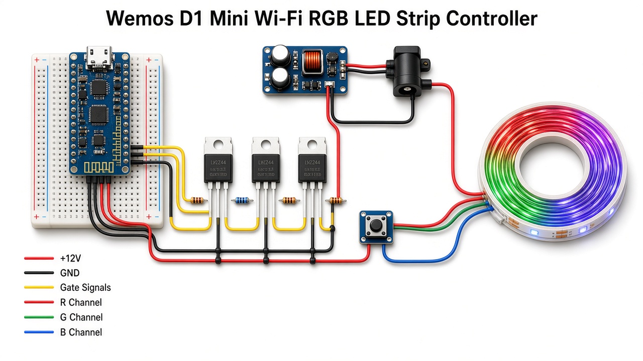
Wemos D1 Mini Wi-Fi RGB LED Strip Controller with Web Colour Picker

Wemos D1 Mini Wi-Fi RGB LED strip controller with three IRLZ44N MOSFETs, buck converter, push button and 12V RGB strip

Build a Wemos D1 Mini Wi-Fi RGB LED strip controller with IRLZ44N MOSFETs, a web colour picker, brightness slider, rainbow mode and a push button. Wiring table, diagram and full code.

  • DifficultyIntermediate
  • Build time2–4 hours
  • Board / MCUWemos D1 Mini (ESP8266)
  • Parts10 items
  • CodeArduino C++

Need it ready-made? Buy Ready Project

This Wemos D1 Mini RGB LED strip controller lets you set any colour and brightness on an ordinary 12V RGB (5050) LED strip from your phone’s browser. No app is needed: the ESP8266 hosts a small web page with a colour picker, a brightness slider, ON/OFF buttons and a smooth rainbow mode. A push button on the board switches the strip on and off without a phone, and the last setting is remembered after a power cut.

It is a practical medium-level IoT project for room backlighting, a TV bias light, a desk or a shop display, and a good way to learn PWM dimming with logic-level MOSFETs.

Wemos D1 Mini Wi-Fi RGB LED strip controller with three IRLZ44N MOSFETs, buck converter, push button and 12V RGB strip

How It Works

  • The strip: a common-anode 12V RGB strip has four wires: +12V and one return wire each for red, green and blue. A colour lights up when its return wire is pulled to ground.
  • MOSFET switches: three IRLZ44N logic-level MOSFETs act as low-side switches. Each gate is driven straight from a 3.3V D1 Mini pin through a 100 Ω resistor, and a 10k pull-down keeps the strip off while the board boots.
  • PWM dimming: the ESP8266 drives D5, D6 and D7 with 1 kHz, 10-bit PWM. The code applies a simple gamma curve so low brightness levels look smooth to the eye.
  • Web control: the board joins your Wi-Fi and serves a page at its IP address. Moving the colour picker or slider sends a short request such as /set?hex=ff7828 and the colour changes instantly.
  • Rainbow mode: the code steps through all 360 hues every 30 ms for a slow, continuous colour fade.
  • Memory and button: colour, brightness, power and mode are stored in EEPROM 3 seconds after the last change, so a slider drag does not wear the flash. The D2 button toggles the strip with a 50 ms debounce.
  • Power: one 12V adapter feeds the strip directly and an LM2596 buck converter makes 5V for the D1 Mini.

Components Required

  • Wemos D1 Mini (ESP8266) – 1
  • 12V RGB 5050 LED strip, common anode, up to 5 m – 1
  • IRLZ44N logic-level N-channel MOSFET – 3
  • Resistors: 100 Ω – 3, 10k – 3
  • LM2596 buck converter module (set to 5V) – 1
  • 12V DC adapter, 2A for 2 m or 5A for 5 m of strip – 1
  • DC barrel jack – 1
  • Tactile push button – 1
  • 470 µF 25V electrolytic capacitor – 1
  • Breadboard or perfboard, screw terminals and jumper wires

Wiring Table

FromToNotes
12V adapter (+)Strip +12V wire and LM2596 IN+
12V adapter (-)LM2596 IN-, MOSFET sources, D1 Mini GOne common ground
LM2596 OUT+D1 Mini 5VAdjust to 5.0V before connecting
LM2596 OUT-D1 Mini G
D1 Mini D5 (GPIO14)IRLZ44N #1 gate via 100 Ω10k from gate to GND
IRLZ44N #1 drainStrip R wireSource to GND
D1 Mini D6 (GPIO12)IRLZ44N #2 gate via 100 Ω10k from gate to GND
IRLZ44N #2 drainStrip G wireSource to GND
D1 Mini D7 (GPIO13)IRLZ44N #3 gate via 100 Ω10k from gate to GND
IRLZ44N #3 drainStrip B wireSource to GND
Push buttonD2 (GPIO4) and GNDUses the internal pull-up
470 µF capacitor+12V and GND at the stripObserve polarity

IRLZ44N pins, with the printed face toward you and legs down: gate, drain, source (left to right).

Connection Diagram

The illustration above shows a typical layout; its wire routes are only for orientation. The pin-accurate drawing below matches the wiring table exactly, so follow it while building.

Wemos D1 Mini RGB Strip Controller – Pin-Accurate Wiring 12V supply 12V DC adapter (+): strip +12V wire and LM2596 IN+ 12V DC adapter (-): common GND, LM2596 IN-, all MOSFET sources Buck converter LM2596 set to 5.0V before connecting the board OUT+ to Wemos 5V pin, OUT- to Wemos G (GND) Red channel D5 (GPIO14) via 100 Ω to IRLZ44N #1 gate, 10k gate to GND MOSFET #1 drain to strip R, source to GND Green channel D6 (GPIO12) via 100 Ω to IRLZ44N #2 gate, 10k gate to GND MOSFET #2 drain to strip G, source to GND Blue channel D7 (GPIO13) via 100 Ω to IRLZ44N #3 gate, 10k gate to GND MOSFET #3 drain to strip B, source to GND Button Push button between D2 (GPIO4) and GND (internal pull-up) Bulk capacitor 470 µF 25V across 12V and GND near the strip connector
Pin-accurate connection diagram for the Wemos D1 Mini RGB LED strip controller.

Code

Install the ESP8266 board package in the Arduino IDE (Boards Manager, search “esp8266”), choose LOLIN(WEMOS) D1 R2 & mini, put your Wi-Fi name and password in place of the placeholders, and upload. No extra libraries are needed. Open the Serial Monitor at 115200 baud to see the board’s IP address, then open that address in your phone’s browser.

/*
  Wemos D1 Mini Wi-Fi RGB LED Strip Controller
  - 12V common-anode RGB (5050) strip driven by 3x IRLZ44N logic-level MOSFETs
  - Web page with colour picker, brightness slider, ON/OFF and Rainbow mode
  - Push button on D2 toggles the strip ON/OFF without a phone
  - Last colour, brightness and mode are saved in EEPROM
  Board: LOLIN(WEMOS) D1 R2 & mini (ESP8266 core). No extra libraries needed.
*/
#include <ESP8266WiFi.h>
#include <ESP8266WebServer.h>
#include <EEPROM.h>

const char* WIFI_SSID = "YOUR_WIFI_SSID";       // <-- your Wi-Fi name
const char* WIFI_PASS = "YOUR_WIFI_PASSWORD";   // <-- your Wi-Fi password

// MOSFET gate pins (each through a 100 ohm resistor, 10k pull-down to GND)
const uint8_t PIN_R = D5;   // GPIO14
const uint8_t PIN_G = D6;   // GPIO12
const uint8_t PIN_B = D7;   // GPIO13
const uint8_t PIN_BTN = D2; // GPIO4, push button to GND

ESP8266WebServer server(80);

// Current settings
uint8_t red = 255, green = 120, blue = 40;  // warm white default
uint8_t brightness = 80;                    // 0-100 %
bool powerOn = true;
bool rainbow = false;

uint16_t hue = 0;                 // used by rainbow mode (0-359)
unsigned long lastStep = 0;
unsigned long lastSaveRequest = 0;
bool savePending = false;

// ---------- EEPROM storage ----------
const uint8_t MAGIC = 0x37;
void saveSettings() {
  EEPROM.write(0, MAGIC);
  EEPROM.write(1, red);
  EEPROM.write(2, green);
  EEPROM.write(3, blue);
  EEPROM.write(4, brightness);
  EEPROM.write(5, powerOn);
  EEPROM.write(6, rainbow);
  EEPROM.commit();
}
void loadSettings() {
  if (EEPROM.read(0) != MAGIC) return;   // first boot: keep defaults
  red = EEPROM.read(1);
  green = EEPROM.read(2);
  blue = EEPROM.read(3);
  brightness = constrain(EEPROM.read(4), 0, 100);
  powerOn = EEPROM.read(5);
  rainbow = EEPROM.read(6);
}
// Delay EEPROM writes so dragging a slider doesn't wear the flash
void requestSave() { savePending = true; lastSaveRequest = millis(); }

// ---------- Output ----------
// Simple gamma correction so low brightness looks smooth
uint16_t gamma10(uint8_t v) {
  float f = v / 255.0;
  return (uint16_t)(f * f * 1023.0 + 0.5);
}
void writeRGB(uint8_t r, uint8_t g, uint8_t b) {
  if (!powerOn) { r = g = b = 0; }
  uint16_t scale = brightness;   // 0-100
  analogWrite(PIN_R, gamma10(r) * scale / 100);
  analogWrite(PIN_G, gamma10(g) * scale / 100);
  analogWrite(PIN_B, gamma10(b) * scale / 100);
}
// Convert hue (0-359) at full saturation to RGB
void hueToRGB(uint16_t h, uint8_t &r, uint8_t &g, uint8_t &b) {
  uint8_t region = h / 60;
  uint8_t rem = (h % 60) * 255 / 60;
  switch (region) {
    case 0: r = 255; g = rem; b = 0; break;
    case 1: r = 255 - rem; g = 255; b = 0; break;
    case 2: r = 0; g = 255; b = rem; break;
    case 3: r = 0; g = 255 - rem; b = 255; break;
    case 4: r = rem; g = 0; b = 255; break;
    default: r = 255; g = 0; b = 255 - rem; break;
  }
}
void applyOutput() {
  if (rainbow) return;   // rainbow updates itself in loop()
  writeRGB(red, green, blue);
}

// ---------- Web page ----------
const char PAGE[] PROGMEM = R"HTML(
<!DOCTYPE html><html><head><meta name="viewport" content="width=device-width,initial-scale=1">
<title>RGB Strip</title>
<style>body{font-family:Arial;text-align:center;background:#111;color:#eee;margin:0;padding:20px}
input[type=color]{width:160px;height:160px;border:none;background:none}
input[type=range]{width:80%}button{font-size:18px;margin:8px;padding:12px 22px;border:0;border-radius:8px}
#on{background:#2e7d32;color:#fff}#off{background:#c62828;color:#fff}#rb{background:#6a1b9a;color:#fff}</style></head>
<body><h2>Wi-Fi RGB Strip</h2>
<input type="color" id="c" value="#ff7828"><br>
<p>Brightness: <span id="bv">80</span>%</p><input type="range" id="br" min="0" max="100" value="80"><br>
<button id="on">ON</button><button id="off">OFF</button><button id="rb">Rainbow</button>
<p id="st"></p>
<script>
function send(q){fetch('/set?'+q).then(r=>r.json()).then(show);}
function show(s){document.getElementById('st').innerText=(s.power?'ON':'OFF')+(s.rainbow?' - Rainbow':'');
 document.getElementById('br').value=s.bright;document.getElementById('bv').innerText=s.bright;
 if(!s.rainbow)document.getElementById('c').value=s.hex;}
c.oninput=e=>send('hex='+e.target.value.substring(1));
br.oninput=e=>{bv.innerText=e.target.value;send('bright='+e.target.value);};
on.onclick=()=>send('power=1');off.onclick=()=>send('power=0');rb.onclick=()=>send('rainbow=1');
fetch('/state').then(r=>r.json()).then(show);
</script></body></html>
)HTML";

String stateJSON() {
  char hex[8];
  snprintf(hex, sizeof(hex), "#%02x%02x%02x", red, green, blue);
  String s = "{\"power\":"; s += powerOn ? 1 : 0;
  s += ",\"rainbow\":"; s += rainbow ? 1 : 0;
  s += ",\"bright\":"; s += brightness;
  s += ",\"hex\":\""; s += hex; s += "\"}";
  return s;
}

void handleRoot() { server.send_P(200, "text/html", PAGE); }
void handleState() { server.send(200, "application/json", stateJSON()); }
void handleSet() {
  if (server.hasArg("hex")) {               // e.g. hex=ff7828
    long v = strtol(server.arg("hex").c_str(), NULL, 16);
    red = (v >> 16) & 0xFF; green = (v >> 8) & 0xFF; blue = v & 0xFF;
    rainbow = false; powerOn = true;
  }
  if (server.hasArg("bright")) brightness = constrain(server.arg("bright").toInt(), 0, 100);
  if (server.hasArg("power")) powerOn = server.arg("power").toInt() == 1;
  if (server.hasArg("rainbow")) { rainbow = server.arg("rainbow").toInt() == 1; powerOn = true; }
  applyOutput();
  requestSave();
  server.send(200, "application/json", stateJSON());
}

// ---------- Button ----------
bool lastBtn = HIGH;
unsigned long lastBtnChange = 0;
void checkButton() {
  bool b = digitalRead(PIN_BTN);
  if (b != lastBtn && millis() - lastBtnChange > 50) {   // 50 ms debounce
    lastBtnChange = millis();
    lastBtn = b;
    if (b == LOW) {            // pressed
      powerOn = !powerOn;
      applyOutput();
      if (!powerOn) writeRGB(0, 0, 0);
      requestSave();
    }
  }
}

void setup() {
  Serial.begin(115200);
  pinMode(PIN_R, OUTPUT); pinMode(PIN_G, OUTPUT); pinMode(PIN_B, OUTPUT);
  pinMode(PIN_BTN, INPUT_PULLUP);
  analogWriteRange(1023);     // 10-bit PWM
  analogWriteFreq(1000);      // 1 kHz, flicker-free for LED strips
  EEPROM.begin(16);
  loadSettings();
  applyOutput();

  WiFi.mode(WIFI_STA);
  WiFi.hostname("rgb-strip");
  WiFi.begin(WIFI_SSID, WIFI_PASS);
  Serial.print("Connecting");
  unsigned long t0 = millis();
  while (WiFi.status() != WL_CONNECTED && millis() - t0 < 20000) {
    delay(300); Serial.print(".");
    checkButton();            // button still works while connecting
  }
  Serial.println();
  if (WiFi.status() == WL_CONNECTED) {
    Serial.print("Open http://"); Serial.println(WiFi.localIP());
  } else {
    Serial.println("Wi-Fi failed - button control only");
  }

  server.on("/", handleRoot);
  server.on("/state", handleState);
  server.on("/set", handleSet);
  server.begin();
}

void loop() {
  server.handleClient();
  checkButton();

  // Rainbow mode: step the hue every 30 ms (full cycle in about 11 s)
  if (rainbow && powerOn && millis() - lastStep > 30) {
    lastStep = millis();
    uint8_t r, g, b;
    hueToRGB(hue, r, g, b);
    writeRGB(r, g, b);
    hue = (hue + 1) % 360;
  }

  // Save settings 3 s after the last change
  if (savePending && millis() - lastSaveRequest > 3000) {
    savePending = false;
    saveSettings();
  }
}

Troubleshooting

ProblemFix
Strip stays fully onThe MOSFET drain and source may be swapped, or the 10k pull-down is missing. Check the gate, drain, source order.
One colour never lightsCheck that channel’s MOSFET and wire. Some strips mark the wires in the order +12V, G, R, B, so the colours may simply be swapped in the wiring.
Colours flicker on cameraRaise the PWM frequency with analogWriteFreq(2000) in setup().
MOSFETs get hotUse real IRLZ44N parts (not IRFZ44N, which needs 10V on the gate) and add a small heatsink for strips over 3 A.
Web page does not openMake sure the phone is on the same Wi-Fi and use the IP address printed in the Serial Monitor.

Ideas to Extend

  • Add an IR receiver (TSOP1738) on D1 to use a cheap 44-key RGB remote as well.
  • Add an LDR so the strip turns on automatically at dusk.
  • Add MQTT so the strip works with Home Assistant.

Wemos D1 Mini Wi-Fi Doorbell with Phone Alerts (ntfy)

Wemos D1 Mini Wi-Fi doorbell breadboard wiring with push button on D5, BC547 buzzer driver on D6 and phone notification

Build a Wemos D1 Mini Wi-Fi doorbell that rings a buzzer and sends a push notification to your phone through ntfy.sh. Wiring table, diagram and full code.

  • DifficultyEasy
  • Build time1–2 hours
  • Board / MCUWemos D1 Mini (ESP8266)
  • Parts8 items
  • CodeArduino C++

Need it ready-made? Buy Ready Project

This Wemos D1 Mini Wi-Fi doorbell turns a simple push button into a smart doorbell. When a visitor presses the button, a buzzer rings at the door and your phone gets a push notification within a second or two, even if you are upstairs or away from home.

The alert is sent through ntfy.sh, a free push notification service that needs no account, no API key and no app server of your own. You just install the free ntfy app on Android or iPhone and subscribe to a topic name that you choose.

Wemos D1 Mini Wi-Fi doorbell breadboard wiring with push button on D5, BC547 buzzer driver on D6 and phone notification

How It Works

  • Button: the doorbell button connects D5 to GND. The ESP8266 internal pull-up keeps D5 HIGH, so a press reads as LOW. The code debounces the press for 50 ms so one press counts once.
  • Buzzer: the D1 Mini pin can only supply a few milliamps, so it switches a BC547 transistor through a 1 kΩ resistor. The transistor connects the 5 V active buzzer to ground and it plays a short ding-dong.
  • Wi-Fi alert: right after the ring, the board sends an HTTPS POST to https://ntfy.sh/your-topic with a title, a high priority and a bell icon. The ntfy app on your phone shows it as a normal notification.
  • Cooldown: if someone presses the button again and again, the buzzer still rings but only one phone alert is sent every 10 seconds, so your phone is not flooded.
  • Status LED: the built-in LED blinks while Wi-Fi connects and lights while an alert is being sent. The board reconnects to Wi-Fi by itself if the router restarts.

Components Required

  • Wemos D1 Mini (ESP8266) – 1
  • Push button (doorbell switch or 12 mm tactile button) – 1
  • 5 V active buzzer – 1
  • BC547 NPN transistor – 1
  • 1 kΩ resistor – 1
  • 5 V USB power adapter with micro-USB cable
  • Breadboard or small perfboard, jumper wires
  • Two-core wire to run the button to the door (optional)

Wiring Table

FromToNotes
Button leg 1D1 Mini D5 (GPIO14)Internal pull-up used, no resistor needed
Button leg 2D1 Mini GND
D1 Mini D6 (GPIO12)1 kΩ resistor, then BC547 baseSwitches the transistor
BC547 emitterD1 Mini GND
BC547 collectorBuzzer – (short leg)Low side switch
Buzzer + (long leg)D1 Mini 5V pin5 V from USB
D1 Mini micro-USB5 V adapterPowers the whole circuit
D4 (GPIO2)Built-in LEDStatus light, no wiring needed

Connection Diagram

The illustration above shows the general breadboard layout. The pin-accurate drawing below matches the wiring table exactly, so follow it when you build the circuit.

Wemos D1 Mini Wi-Fi Doorbell – Pin-Accurate Wiring Wemos D1 Mini 5V pin: USB 5 V supply (buzzer +) GND pin: common ground D5 (GPIO14): push button D6 (GPIO12): 1 kΩ to BC547 base D4 (GPIO2): built-in status LED Doorbell Button Leg 1: D5 (internal pull-up enabled) Leg 2: GND BC547 Driver Base (B): 1 kΩ from D6 Emitter (E): GND Collector (C): buzzer – (negative) Active Buzzer 5 V + (long leg): 5V pin – (short leg): BC547 collector Signal flow: button press on D5, buzzer rings through BC547 on D6, Wi-Fi sends an HTTPS alert to ntfy.sh, phone shows it.
Pin-accurate connection diagram for the Wemos D1 Mini Wi-Fi doorbell.

Setting Up the Phone Alerts

  • Install the free ntfy app from the Play Store or App Store.
  • Tap the + button and subscribe to a topic name, for example raj-home-doorbell-7k29. Use a long, hard-to-guess name, because anyone who knows the topic can read it.
  • Put the same topic name in NTFY_TOPIC in the code below.

Code

Install the ESP8266 board package in the Arduino IDE (Boards Manager, search “esp8266”), choose LOLIN(WEMOS) D1 R2 & mini as the board, replace the Wi-Fi and topic placeholders, and upload. No extra libraries are needed.

/*
  Wemos D1 Mini Wi-Fi Doorbell with ntfy Phone Alerts
  ---------------------------------------------------
  - Press the doorbell button: the buzzer rings and a push
    notification is sent to your phone through ntfy.sh.
  - Install the free "ntfy" app on your phone and subscribe
    to the same topic name you set below.

  Wiring (see the wiring table in the post):
    Push button : D5 (GPIO14) to GND  (internal pull-up used)
    Buzzer      : D6 (GPIO12) -> 1k -> BC547 base, buzzer on collector
    Status LED  : built-in LED on D4 (GPIO2, active LOW)
*/

#include <ESP8266WiFi.h>
#include <ESP8266HTTPClient.h>
#include <WiFiClientSecure.h>

// ---------- User settings (replace the placeholders) ----------
const char* WIFI_SSID     = "YOUR_WIFI_SSID";
const char* WIFI_PASSWORD = "YOUR_WIFI_PASSWORD";
// Pick a long, hard-to-guess topic name. Anyone who knows it can read it.
const char* NTFY_TOPIC    = "YOUR_UNIQUE_DOORBELL_TOPIC";
// ---------------------------------------------------------------

const uint8_t BUTTON_PIN = D5;   // GPIO14
const uint8_t BUZZER_PIN = D6;   // GPIO12 (drives BC547)
const uint8_t LED_PIN    = LED_BUILTIN; // GPIO2, LOW = ON

const unsigned long DEBOUNCE_MS = 50;     // ignore contact bounce
const unsigned long COOLDOWN_MS = 10000;  // max one alert every 10 s

unsigned long lastAlert = 0;
bool lastReading = HIGH;
bool stableState = HIGH;
unsigned long lastChange = 0;

// Ring the buzzer in a simple "ding-dong" pattern
void ringBuzzer() {
  for (int i = 0; i < 2; i++) {
    digitalWrite(BUZZER_PIN, HIGH);
    delay(300);
    digitalWrite(BUZZER_PIN, LOW);
    delay(150);
  }
}

// Connect (or reconnect) to Wi-Fi, blinking the LED while waiting
void connectWiFi() {
  if (WiFi.status() == WL_CONNECTED) return;
  Serial.print("Connecting to Wi-Fi");
  WiFi.mode(WIFI_STA);
  WiFi.begin(WIFI_SSID, WIFI_PASSWORD);
  unsigned long start = millis();
  while (WiFi.status() != WL_CONNECTED && millis() - start < 20000) {
    digitalWrite(LED_PIN, !digitalRead(LED_PIN));
    delay(250);
    Serial.print(".");
  }
  digitalWrite(LED_PIN, HIGH); // LED off
  Serial.println(WiFi.status() == WL_CONNECTED ? " connected" : " failed");
}

// Send a push notification through ntfy.sh (HTTPS POST)
bool sendNotification() {
  connectWiFi();
  if (WiFi.status() != WL_CONNECTED) return false;

  WiFiClientSecure client;
  client.setInsecure();          // skip certificate check (simple setup)
  HTTPClient http;
  String url = String("https://ntfy.sh/") + NTFY_TOPIC;
  if (!http.begin(client, url)) return false;

  http.addHeader("Title", "Doorbell");
  http.addHeader("Priority", "high");
  http.addHeader("Tags", "bell");
  int code = http.POST("Someone is at the door!");
  http.end();

  Serial.printf("ntfy response: %d\n", code);
  return code == 200;
}

void setup() {
  Serial.begin(115200);
  pinMode(BUTTON_PIN, INPUT_PULLUP);
  pinMode(BUZZER_PIN, OUTPUT);
  pinMode(LED_PIN, OUTPUT);
  digitalWrite(BUZZER_PIN, LOW);
  digitalWrite(LED_PIN, HIGH);
  connectWiFi();
}

void loop() {
  // --- Debounce the button ---
  bool reading = digitalRead(BUTTON_PIN);
  if (reading != lastReading) {
    lastChange = millis();
    lastReading = reading;
  }
  if (millis() - lastChange > DEBOUNCE_MS && reading != stableState) {
    stableState = reading;

    // Button pressed (pin pulled LOW)
    if (stableState == LOW) {
      ringBuzzer();
      if (millis() - lastAlert > COOLDOWN_MS || lastAlert == 0) {
        lastAlert = millis();
        digitalWrite(LED_PIN, LOW);           // LED on while sending
        bool ok = sendNotification();
        digitalWrite(LED_PIN, HIGH);
        Serial.println(ok ? "Alert sent" : "Alert failed");
      }
    }
  }

  // Keep Wi-Fi alive in the background
  if (WiFi.status() != WL_CONNECTED) connectWiFi();
}

Testing

  • Open the Serial Monitor at 115200 baud and check that it prints “connected”.
  • Press the button. The buzzer should play two beeps and the monitor should show “ntfy response: 200” and “Alert sent”.
  • Your phone should show a Doorbell notification saying “Someone is at the door!”
  • Press again within 10 seconds: the buzzer rings but no second alert is sent.

Troubleshooting

ProblemFix
No notification on the phoneCheck that the topic in the app and in the code match exactly, and that the phone has internet.
ntfy response is -1The board could not reach ntfy.sh. Check the Wi-Fi name and password and that the router has internet.
Buzzer does not soundCheck the transistor pins (E, B, C) and use an active buzzer, not a passive one.
One press gives two alertsIncrease DEBOUNCE_MS to 100 or use a better quality button.

Ideas to Extend

  • Add an ESP32-CAM so the alert includes a photo of the visitor.
  • Run the board on an 18650 cell with deep sleep so it works without a wall adapter.
  • Send the alert to a self-hosted ntfy server on your own network for full privacy.

Wemos D1 Mini Smart Aquarium Controller with Heater, Light & Fish Feeder

Wemos D1 Mini smart aquarium controller with DS18B20 probe, 2-channel relay and SG90 servo fish feeder

Build a Wemos D1 Mini smart aquarium controller with a DS18B20 thermostat for the heater, a scheduled LED light, an SG90 servo fish feeder and a Wi-Fi web dashboard. Wiring table, diagram and full code.

  • DifficultyAdvanced
  • Build time5–8 hours
  • Board / MCUWemos D1 Mini (ESP8266)
  • Parts9 items
  • CodeArduino C++

Need it ready-made? Buy Ready Project

This Wemos D1 Mini smart aquarium controller looks after a fish tank on its own. A waterproof DS18B20 probe measures the water temperature and switches the heater through a relay, a second relay turns the aquarium light on and off on a daily schedule, and a small SG90 servo drops food into the tank twice a day. Everything can be checked and controlled from a web dashboard on your phone over home Wi-Fi.

It is a big combination project that brings together a 1-Wire sensor, relays, a servo, NTP internet time and a web server on one cheap ESP8266 board. The heater thermostat keeps working even if Wi-Fi goes down.

Wemos D1 Mini smart aquarium controller with DS18B20 probe, 2-channel relay and SG90 servo fish feeder

How the Smart Aquarium Controller Works

  • Temperature control: every 2 seconds the D1 Mini reads the DS18B20 probe. If the water is more than 0.5 °C below the target (26 °C by default) the heater relay turns ON, and when it is 0.5 °C above the target the relay turns OFF. This gap (hysteresis) stops the relay clicking on and off.
  • Fail-safe: if the probe is unplugged or the water goes above 31 °C, the heater is forced OFF.
  • Light schedule: after connecting to Wi-Fi the board gets the time from an NTP server (set to India time, UTC+5:30). The light relay is ON from 08:00 to 20:00. You can override it from the dashboard and press Auto to go back to the schedule.
  • Automatic feeder: at 09:00 and 18:00 the servo tips a small food container to 120° and back, dropping a pinch of food. A Feed now button does the same on demand. The servo is detached after each feed so it does not buzz or jitter.
  • Web dashboard: open the IP address shown in the Serial Monitor to see the water temperature, heater and light state and the last feeding time, and to change the target temperature in 0.5 °C steps.

Components Required

  • Wemos D1 Mini (ESP8266) – 1
  • DS18B20 waterproof temperature probe (stainless steel, 1 m cable) – 1
  • 4.7 kΩ resistor (pull-up for the DS18B20) – 1
  • 2-channel 5 V relay module (opto-isolated, contacts rated 10 A 250 V) – 1
  • SG90 micro servo – 1, with a small plastic pill box or bottle cap as the food container
  • 5 V 2 A USB adapter and USB cable (powers the D1 Mini, relay and servo)
  • 470 µF / 10 V electrolytic capacitor across 5 V and GND near the servo – 1
  • Aquarium heater and aquarium LED light (your existing ones)
  • Breadboard or perfboard, jumper wires, screw terminals and a closed plastic enclosure

Wiring Table

Module pinWemos D1 Mini pinNotes
DS18B20 red (VDD)3V3–
DS18B20 black (GND)GND–
DS18B20 yellow (DATA)D2 (GPIO4)4.7 kΩ pull-up from DATA to 3V3
Relay module VCC5VPowered from the USB 5 V
Relay module GNDGNDCommon ground
Relay IN1D1 (GPIO5)Heater relay
Relay IN2D5 (GPIO14)Light relay
Servo red5VAdd 470 µF across 5 V and GND
Servo brownGND–
Servo orange (signal)D6 (GPIO12)Feeder servo
Relay 1 COM / NOHeater live wireHeater ON when relay is ON
Relay 2 COM / NOLight live wireLight ON when relay is ON

Most cheap relay modules switch ON when the input is LOW, and the sketch is set for that (RELAY_ACTIVE_LOW = true). If your module switches ON with a HIGH input, change it to false. If the relays do not click reliably with the 3.3 V signal, use a module marked as 3.3 V compatible.

Connection Diagram

The illustration at the top shows the general layout. The pin-accurate drawing below matches the wiring table exactly.

Wemos D1 Mini Smart Aquarium Controller – Pin-Accurate Wiring Wemos D1 Mini D2 (GPIO4) DS18B20 DATA (yellow); 4.7 kΩ from DATA to 3V3 D1 (GPIO5) Relay module IN1 → aquarium heater D5 (GPIO14) Relay module IN2 → aquarium LED light D6 (GPIO12) SG90 servo signal (orange) → fish feeder 3V3 DS18B20 VDD (red) 5V Relay VCC + servo red wire (from 5 V 2 A adapter) GND DS18B20 black, relay GND, servo brown: common GND Relay contacts (COM / NO) switch the heater and light. Mains wiring must be enclosed and done by a qualified person. Avoid D3, D4 and D8 for these loads: they are boot-strapping pins on the ESP8266.
Pin-accurate connection diagram for the Wemos D1 Mini smart aquarium controller.

Arduino Code

In the Arduino IDE install the ESP8266 board package, select LOLIN(WEMOS) D1 R2 & mini, and install the OneWire and DallasTemperature libraries from the Library Manager. The Servo library comes with the ESP8266 core. Put your own Wi-Fi name and password in place of the placeholders before uploading.

/*
  Wemos D1 Mini Smart Aquarium Controller
  - DS18B20 water temperature probe
  - Relay 1: aquarium heater (thermostat with hysteresis)
  - Relay 2: aquarium LED light (on/off schedule from NTP time)
  - SG90 servo: automatic fish feeder (twice a day + button on web page)
  - Web dashboard on the local Wi-Fi network
  Board: LOLIN(WEMOS) D1 R2 & mini  (ESP8266 core 3.x)
  Libraries: OneWire, DallasTemperature (Servo is included in the ESP8266 core)
*/
#include <ESP8266WiFi.h>
#include <ESP8266WebServer.h>
#include <OneWire.h>
#include <DallasTemperature.h>
#include <Servo.h>
#include <time.h>

// ---------- Wi-Fi (replace with your own) ----------
const char* WIFI_SSID     = "YOUR_WIFI_SSID";
const char* WIFI_PASSWORD = "YOUR_WIFI_PASSWORD";

// ---------- Pins ----------
const uint8_t PIN_TEMP   = D2;  // GPIO4  - DS18B20 data (4.7k pull-up to 3V3)
const uint8_t PIN_HEATER = D1;  // GPIO5  - Relay IN1 (heater)
const uint8_t PIN_LIGHT  = D5;  // GPIO14 - Relay IN2 (LED light)
const uint8_t PIN_SERVO  = D6;  // GPIO12 - Servo signal

// Most low-cost relay modules switch ON when IN is LOW. Set false if yours is active-HIGH.
const bool RELAY_ACTIVE_LOW = true;

// ---------- Settings ----------
float targetTemp = 26.0;          // degrees C
const float HYSTERESIS = 0.5;     // heater ON below target-0.5, OFF above target+0.5
const float MAX_SAFE_TEMP = 31.0; // heater forced OFF above this
int lightOnHour  = 8;             // light ON at 08:00
int lightOffHour = 20;            // light OFF at 20:00
const int FEED_HOURS[] = {9, 18}; // feed at 09:00 and 18:00
const int FEED_COUNT = sizeof(FEED_HOURS) / sizeof(FEED_HOURS[0]);
const long GMT_OFFSET_SEC = 19800; // India (IST, UTC+5:30)

OneWire oneWire(PIN_TEMP);
DallasTemperature sensors(&oneWire);
Servo feeder;
ESP8266WebServer server(80);

float waterTemp = NAN;
bool heaterOn = false;
bool lightOn = false;
bool lightManual = false;         // true = user overrode the schedule
int lastFeedDay = -1, lastFeedHour = -1;
String lastFeedTime = "never";
unsigned long lastRead = 0;

void setRelay(uint8_t pin, bool on) {
  digitalWrite(pin, (on ^ RELAY_ACTIVE_LOW) ? HIGH : LOW);
}

String nowString() {
  time_t now = time(nullptr);
  if (now < 100000) return "time not synced";
  struct tm* t = localtime(&now);
  char buf[20];
  snprintf(buf, sizeof(buf), "%02d:%02d:%02d", t->tm_hour, t->tm_min, t->tm_sec);
  return String(buf);
}

void feedFish() {
  feeder.attach(PIN_SERVO, 500, 2400);
  feeder.write(0);   delay(400);
  feeder.write(120); delay(700);   // tip the food container
  feeder.write(0);   delay(600);
  feeder.detach();                 // stop jitter and save power
  lastFeedTime = nowString();
  Serial.println("Fed the fish at " + lastFeedTime);
}

void readTemperature() {
  sensors.requestTemperatures();
  float t = sensors.getTempCByIndex(0);
  waterTemp = (t == DEVICE_DISCONNECTED_C) ? NAN : t;
}

void controlHeater() {
  if (isnan(waterTemp) || waterTemp >= MAX_SAFE_TEMP) {
    heaterOn = false;                    // fail safe: sensor missing or too hot
  } else if (waterTemp < targetTemp - HYSTERESIS) {
    heaterOn = true;
  } else if (waterTemp > targetTemp + HYSTERESIS) {
    heaterOn = false;
  }
  setRelay(PIN_HEATER, heaterOn);
}

void runSchedule() {
  time_t now = time(nullptr);
  if (now < 100000) return;              // wait for NTP
  struct tm* t = localtime(&now);
  if (!lightManual) {
    lightOn = (t->tm_hour >= lightOnHour && t->tm_hour < lightOffHour);
  }
  // Clear manual override at the next scheduled switch time
  if (t->tm_min == 0 && t->tm_sec < 2 && (t->tm_hour == lightOnHour || t->tm_hour == lightOffHour)) {
    lightManual = false;
  }
  setRelay(PIN_LIGHT, lightOn);
  for (int i = 0; i < FEED_COUNT; i++) {
    if (t->tm_hour == FEED_HOURS[i] && t->tm_min == 0 &&
        !(lastFeedDay == t->tm_yday && lastFeedHour == t->tm_hour)) {
      lastFeedDay = t->tm_yday;
      lastFeedHour = t->tm_hour;
      feedFish();
    }
  }
}

void handleRoot() {
  String html = F("<!DOCTYPE html><html><head><meta name='viewport' content='width=device-width,initial-scale=1'>"
                  "<meta http-equiv='refresh' content='10'><title>Aquarium</title>"
                  "<style>body{font-family:Arial;text-align:center;background:#e3f2fd}"
                  ".c{background:#fff;margin:10px auto;padding:12px;max-width:340px;border-radius:10px}"
                  "a{display:inline-block;margin:4px;padding:10px 14px;background:#1976d2;color:#fff;border-radius:6px;text-decoration:none}</style></head><body>"
                  "<h2>Smart Aquarium</h2>");
  html += "<div class='c'><h3>Water: " + (isnan(waterTemp) ? String("sensor error") : String(waterTemp, 1) + " &deg;C") + "</h3>";
  html += "Target: " + String(targetTemp, 1) + " &deg;C<br>Heater: " + String(heaterOn ? "ON" : "OFF");
  html += "<br><a href='/temp?d=-0.5'>-0.5</a><a href='/temp?d=0.5'>+0.5</a></div>";
  html += "<div class='c'>Light: " + String(lightOn ? "ON" : "OFF") + (lightManual ? " (manual)" : " (schedule)");
  html += "<br><a href='/light?s=1'>Light ON</a><a href='/light?s=0'>Light OFF</a><a href='/light?s=a'>Auto</a></div>";
  html += "<div class='c'>Last feed: " + lastFeedTime + "<br><a href='/feed'>Feed now</a></div>";
  html += "<p>Time: " + nowString() + "</p></body></html>";
  server.send(200, "text/html", html);
}

void redirectHome() { server.sendHeader("Location", "/"); server.send(303); }

void setup() {
  Serial.begin(115200);
  pinMode(PIN_HEATER, OUTPUT);
  pinMode(PIN_LIGHT, OUTPUT);
  setRelay(PIN_HEATER, false);           // everything OFF at boot
  setRelay(PIN_LIGHT, false);
  sensors.begin();

  WiFi.mode(WIFI_STA);
  WiFi.begin(WIFI_SSID, WIFI_PASSWORD);
  Serial.print("Connecting to Wi-Fi");
  unsigned long start = millis();
  while (WiFi.status() != WL_CONNECTED && millis() - start < 20000) { delay(500); Serial.print('.'); }
  Serial.println();
  if (WiFi.status() == WL_CONNECTED) Serial.println("Dashboard: http://" + WiFi.localIP().toString());
  else Serial.println("Wi-Fi failed - heater thermostat still works offline");

  configTime(GMT_OFFSET_SEC, 0, "pool.ntp.org", "time.nist.gov");

  server.on("/", handleRoot);
  server.on("/feed", []() { feedFish(); redirectHome(); });
  server.on("/temp", []() {
    targetTemp = constrain(targetTemp + server.arg("d").toFloat(), 20.0, 30.0);
    redirectHome();
  });
  server.on("/light", []() {
    String s = server.arg("s");
    if (s == "a") lightManual = false;
    else { lightManual = true; lightOn = (s == "1"); setRelay(PIN_LIGHT, lightOn); }
    redirectHome();
  });
  server.begin();
}

void loop() {
  server.handleClient();
  if (millis() - lastRead > 2000) {      // read and control every 2 s
    lastRead = millis();
    readTemperature();
    controlHeater();
    runSchedule();
    Serial.printf("Temp %.2f C, heater %s, light %s\n", waterTemp, heaterOn ? "ON" : "OFF", lightOn ? "ON" : "OFF");
  }
}

Setup and Testing

  • Upload the sketch, open the Serial Monitor at 115200 baud and note the dashboard IP address.
  • Test the probe first: hold it in your hand and watch the temperature rise in the Serial Monitor.
  • Test the relays with a small lamp before connecting the real heater.
  • Adjust the servo angle (120°) and the container opening so one feed drops only a small pinch of food.
  • Change lightOnHour, lightOffHour and FEED_HOURS to suit your fish.

Troubleshooting

ProblemFix
Temperature shows sensor error or -127 °CCheck the 4.7 kΩ pull-up between DATA and 3V3 and the DS18B20 wire colours.
Relays work the opposite wayChange RELAY_ACTIVE_LOW in the sketch.
Board resets when the servo movesUse a 2 A adapter and add the 470 µF capacitor across the servo supply.
Light and feeder do not follow the scheduleThe board has no internet time yet. Check Wi-Fi and that the dashboard shows the correct time.
Dashboard does not openMake sure your phone is on the same Wi-Fi network and use the IP from the Serial Monitor.

Safety Note

Aquarium heaters and lights run on 230 V mains. Keep mains wiring inside a closed box, away from water, use relays rated for the load and get help from a qualified electrician. Never put the electronics where water can splash on them.

Ideas to Extend

  • Add a water level float switch to warn when the tank needs topping up.
  • Send a Telegram or email alert when the temperature goes out of range.
  • Add a 0.96 inch OLED to show the temperature on the tank itself.
  • Use a third relay for the air pump or filter with its own schedule.

Wemos D1 Mini NTP Clock with MAX7219 LED Matrix Display

Illustrated wiring overview of a Wemos D1 Mini ESP8266 connected to a 4-in-1 MAX7219 LED dot matrix display showing the time

Build an internet-synced Wi-Fi clock with a Wemos D1 Mini (ESP8266) and a MAX7219 4-in-1 LED matrix, with auto brightness and a 12/24-hour button. Wiring table, diagram and full code included.

  • DifficultyIntermediate
  • Build time2–4 hours
  • Board / MCUWemos D1 Mini (ESP8266)
  • Parts7 items
  • CodeArduino C++

Need it ready-made? Buy Ready Project

This Wemos D1 Mini NTP clock shows the exact time on a bright red MAX7219 4-in-1 LED dot matrix. The ESP8266 on the Wemos joins your Wi-Fi, fetches the time from internet time servers (NTP), and keeps it correct forever, so you never need to set it or add an RTC battery module.

It is a medium-level project that adds two useful touches: an LDR that dims the display at night and brightens it in daylight, and a push button that switches between 12-hour and 24-hour format. Every minute the clock also scrolls the day and date across the matrix. The time zone is set to India Standard Time (UTC+5:30) by default.

How the NTP Clock Works

  • Wi-Fi and NTP: on power-up the Wemos connects to your router, then calls configTime() with the time zone string IST-5:30 and two NTP servers. The ESP8266 SNTP client fetches the time and quietly re-syncs about once an hour.
  • Keeping time: between syncs the ESP8266’s internal timer keeps the clock running, so a short Wi-Fi drop does not stop it.
  • The display: the four 8×8 blocks of the MAX7219 module form a 32×8 screen. The MD_Parola library draws HH:MM in the centre with a colon that blinks every second, and scrolls the date once a minute.
  • SPI link: the matrix uses the ESP8266’s hardware SPI: CLK on D5, DIN (data) on D7 and CS (chip select) on D8. Only three signal wires are needed.
  • Auto brightness: the LDR and a 10 kΩ resistor form a voltage divider on A0. More light gives a higher reading, which the code maps to intensity 0 to 15.
  • Format button: a press on D3 (pulled LOW to GND) toggles 12-hour and 24-hour mode.

Components Required

  • Wemos D1 Mini (ESP8266) – 1
  • MAX7219 4-in-1 LED dot matrix module (32×8, FC16 type) – 1
  • LDR (light dependent resistor, 5 mm) – 1
  • 10 kΩ resistor – 1
  • Tactile push button – 1
  • Micro-USB cable and 5 V 2 A USB adapter
  • Breadboard and jumper wires (female-to-male for the matrix header)

Wiring Table (Pin-to-Pin)

PartPinWemos D1 Mini PinNotes
MAX7219 matrixVCC5VThe matrix draws up to ~300 mA at full brightness
MAX7219 matrixGNDGNDCommon ground
MAX7219 matrixDIND7 (GPIO13, MOSI)Use the input side of the module
MAX7219 matrixCSD8 (GPIO15)Chip select / LOAD
MAX7219 matrixCLKD5 (GPIO14, SCK)SPI clock
LDRLeg 13V3
LDRLeg 2A0Also connect the 10 kΩ resistor here
10 kΩ resistorOther endGNDCompletes the light divider
Push buttonLeg 1D3 (GPIO0)Internal pull-up is used
Push buttonLeg 2GNDDo not hold it while powering on

Connection Diagram

The illustration below is also the featured image and gives a quick view of the layout. Its pin labels are artistic and not exact, so wire the circuit using the pin-accurate drawing under it, which matches the wiring table.

Illustrated wiring overview of a Wemos D1 Mini ESP8266 connected to a 4-in-1 MAX7219 LED dot matrix display showing the time
Overview: Wemos D1 Mini on a breadboard driving a 4-in-1 MAX7219 dot matrix clock.
Wemos D1 Mini NTP Clock – Pin-Accurate Wiring Wemos D1 Mini RST TX A0 RX D0 D1 D5 (CLK) D2 D6 D3 D7 (MOSI) D4 D8 (CS) GND 3V3 5V MAX7219 4-in-1 (FC16) input side Wemos 5V Matrix VCC Wemos GND Matrix GND Wemos D7 Matrix DIN Wemos D8 Matrix CS Wemos D5 Matrix CLK LDR: 3V3 → LDR → A0 → 10 kΩ → GND Button: D3 → push button → GND (internal pull-up) Power: micro-USB 5 V, 2 A adapter recommended
Pin-accurate connection diagram for the Wemos D1 Mini NTP clock.

Arduino Code

Install the ESP8266 board package in the Arduino IDE, select LOLIN(WEMOS) D1 R2 & mini, and install MD_Parola and MD_MAX72XX from the Library Manager. Replace the Wi-Fi placeholders with your own network name and password before uploading. The sketch was compile-tested with ESP8266 core 3.1.2.

/*
  Wemos D1 Mini NTP Clock with MAX7219 4-in-1 Dot Matrix
  - Gets the exact time from the internet (NTP) over Wi-Fi
  - Shows HH:MM with a blinking colon on a 32x8 LED matrix
  - Scrolls the day and date every minute
  - LDR on A0 sets the display brightness automatically
  - Push button on D3 toggles 12-hour / 24-hour format

  Libraries: MD_Parola and MD_MAX72XX (Library Manager)
  Board: LOLIN(WEMOS) D1 R2 & mini (ESP8266 core)
*/

#include <ESP8266WiFi.h>
#include <time.h>
#include <MD_Parola.h>
#include <MD_MAX72xx.h>
#include <SPI.h>

// ---------- Wi-Fi (replace with your own) ----------
const char* WIFI_SSID     = "YOUR_WIFI_SSID";
const char* WIFI_PASSWORD = "YOUR_WIFI_PASSWORD";

// ---------- Time zone ----------
// India Standard Time is UTC+5:30. POSIX TZ strings use the opposite sign.
const char* TZ_INFO = "IST-5:30";
const char* NTP_SERVER1 = "pool.ntp.org";
const char* NTP_SERVER2 = "time.google.com";

// ---------- Display ----------
#define HARDWARE_TYPE MD_MAX72XX::FC16_HW   // most blue 4-in-1 modules are FC16
#define MAX_DEVICES   4                     // four 8x8 blocks = 32x8
#define CS_PIN        D8                    // CS/LOAD (hardware SPI: CLK=D5, DIN=D7)

MD_Parola display = MD_Parola(HARDWARE_TYPE, CS_PIN, MAX_DEVICES);

// ---------- Inputs ----------
#define BUTTON_PIN D3   // to GND, uses internal pull-up
#define LDR_PIN    A0   // LDR + 10k divider

bool use24h = true;
bool lastButton = HIGH;
unsigned long lastButtonMs = 0;
int lastMinuteScrolled = -1;
char timeText[12];
char dateText[40];

const char* DAYS[]   = {"Sun", "Mon", "Tue", "Wed", "Thu", "Fri", "Sat"};
const char* MONTHS[] = {"Jan", "Feb", "Mar", "Apr", "May", "Jun",
                        "Jul", "Aug", "Sep", "Oct", "Nov", "Dec"};

void connectWiFi() {
  WiFi.mode(WIFI_STA);
  WiFi.begin(WIFI_SSID, WIFI_PASSWORD);
  display.displayText("WiFi..", PA_CENTER, 0, 0, PA_PRINT, PA_NO_EFFECT);
  display.displayAnimate();
  unsigned long start = millis();
  while (WiFi.status() != WL_CONNECTED && millis() - start < 20000) {
    delay(250);
    Serial.print('.');
  }
  Serial.println(WiFi.status() == WL_CONNECTED ? "\nWi-Fi connected" : "\nWi-Fi failed");
}

// Map the LDR reading (0-1023) to MAX7219 intensity (0-15)
void updateBrightness() {
  int raw = analogRead(LDR_PIN);
  int level = map(raw, 50, 1000, 0, 15);
  display.setIntensity(constrain(level, 0, 15));
}

void checkButton() {
  bool now = digitalRead(BUTTON_PIN);
  if (now == LOW && lastButton == HIGH && millis() - lastButtonMs > 250) {
    use24h = !use24h;           // toggle the format
    lastButtonMs = millis();
  }
  lastButton = now;
}

void setup() {
  Serial.begin(115200);
  pinMode(BUTTON_PIN, INPUT_PULLUP);

  display.begin();
  display.setIntensity(4);
  display.displayClear();

  connectWiFi();

  // Start SNTP with the India time zone; the ESP8266 re-syncs automatically
  configTime(TZ_INFO, NTP_SERVER1, NTP_SERVER2);

  // Wait until a valid time arrives (year > 2020)
  display.displayText("Sync..", PA_CENTER, 0, 0, PA_PRINT, PA_NO_EFFECT);
  display.displayAnimate();
  time_t now = time(nullptr);
  while (now < 1600000000) {
    delay(200);
    now = time(nullptr);
  }
  display.displayClear();
}

void loop() {
  checkButton();

  if (WiFi.status() != WL_CONNECTED) {
    WiFi.reconnect();   // clock keeps running from the internal timer meanwhile
  }

  time_t now = time(nullptr);
  struct tm* t = localtime(&now);

  // Once a minute (at second 30) scroll the day and date
  if (t->tm_sec == 30 && t->tm_min != lastMinuteScrolled) {
    lastMinuteScrolled = t->tm_min;
    snprintf(dateText, sizeof(dateText), "%s %02d %s %d",
             DAYS[t->tm_wday], t->tm_mday, MONTHS[t->tm_mon], t->tm_year + 1900);
    display.displayText(dateText, PA_CENTER, 40, 0, PA_SCROLL_LEFT, PA_SCROLL_LEFT);
    while (!display.displayAnimate()) {
      yield();          // keep Wi-Fi alive during the scroll
      checkButton();
    }
  }

  // Build HH:MM, blinking the colon every second
  int hour = t->tm_hour;
  if (!use24h) {
    hour = hour % 12;
    if (hour == 0) hour = 12;
  }
  char sep = (t->tm_sec % 2 == 0) ? ':' : ' ';
  snprintf(timeText, sizeof(timeText), "%02d%c%02d", hour, sep, t->tm_min);

  updateBrightness();
  display.displayText(timeText, PA_CENTER, 0, 0, PA_PRINT, PA_NO_EFFECT);
  display.displayAnimate();

  delay(100);
}

Code Explained

  • configTime(TZ_INFO, ...) starts SNTP and applies the time zone, so localtime() returns Indian time directly. Change TZ_INFO for other countries, for example GMT0BST,M3.5.0/1,M10.5.0 for the UK.
  • FC16_HW matches most blue 4-in-1 modules. If the characters look mirrored or scrambled, try PAROLA_HW or GENERIC_HW.
  • updateBrightness() maps the LDR reading to the MAX7219’s 16 brightness steps. Adjust the 50 and 1000 limits to suit your room.
  • The date scroll uses PA_SCROLL_LEFT, and yield() inside the scroll loop keeps the Wi-Fi stack happy.

Troubleshooting

ProblemFix
Display stays on “WiFi..” or “Sync..”Check the SSID and password, and use a 2.4 GHz network. The ESP8266 does not support 5 GHz Wi-Fi.
Text is mirrored, upside down or garbledChange HARDWARE_TYPE to PAROLA_HW or GENERIC_HW, and make sure the wires go to the input (DIN) side of the module.
Random dots or flickerThe 3.3 V data signal is at the edge of what the MAX7219 accepts at 5 V. Keep wires short, or add a 74AHCT125 level shifter on DIN, CS and CLK.
Time is off by 5.5 hoursThe time zone string is wrong. For India it must be IST-5:30 (the minus sign is correct).
Board will not boot with the button pressedD3 is GPIO0, a boot pin. Release the button while powering on, or move the button to D1 or D2 and change BUTTON_PIN.
Wemos resets at high brightnessUse a good 5 V 2 A adapter and a short USB cable, since the matrix can draw a lot of current.

Ideas to Extend This Project

  • Add a DHT22 or BME280 sensor and scroll the room temperature with the date.
  • Add a buzzer and an alarm time set from a small web page served by the ESP8266.
  • Chain a second 4-in-1 module (MAX_DEVICES = 8) to show seconds too.
  • Use WiFiManager so the Wi-Fi details can be entered from a phone instead of in the code.

FAQ

Do I need an RTC module like the DS3231? No. The time comes from the internet and the ESP8266 keeps it between syncs. Add an RTC only if the clock must work without Wi-Fi after a power cut.

Can I use a NodeMCU instead of the Wemos D1 Mini? Yes. The D5, D7, D8, D3 and A0 pins have the same names on a NodeMCU, so the wiring and code stay the same.

How accurate is it? NTP keeps it within a fraction of a second of real time, and it re-syncs automatically, so it never drifts like a normal quartz clock.

Wemos D1 Mini Rain Detector with Wi-Fi Alert

Wemos D1 Mini rain detector on a breadboard with an LM393 module, buzzer, LED and YL-83 rain pad

Build a Wemos D1 Mini rain detector with a YL-83 sensor, buzzer and LED alarm, plus a Wi-Fi page showing DRY/WET. Wiring table, diagram and full code.

  • DifficultyEasy
  • Build time1–2 hours
  • Board / MCUWemos D1 Mini (ESP8266)
  • Parts8 items
  • CodeArduino C++

Need it ready-made? Buy Ready Project

Wemos D1 Mini rain detector on a breadboard with an LM393 module, buzzer, LED and YL-83 rain pad

This Wemos D1 Mini rain detector tells you the moment rain starts to fall. A cheap YL-83 / FC-37 rain pad sits outside, the Wemos D1 Mini (ESP8266) reads it, and an active buzzer and a red LED come on as soon as the pad gets wet. The board also joins your home Wi-Fi and serves a small status page, so you can open it on your phone and see DRY or WET together with the live analog reading.

It is a small, beginner-friendly build: four parts, a handful of jumper wires and one sketch. It is handy for reminding you to bring the washing in, closing a skylight by hand before the storm, or as the first block of a bigger weather station.

How the Rain Detector Works

The rain pad is a board with two interleaved copper tracks. When it is dry the tracks are not connected, so the resistance between them is very high. A drop of water bridges the tracks and the resistance falls. The more water on the pad, the lower the resistance.

The small control module that comes with the pad has an LM393 comparator and a sensitivity potentiometer. It gives you two outputs:

  • AO (analog output): a voltage that falls as the pad gets wetter. The Wemos reads it on A0, its only analog input, as a number from 0 to 1023. A dry pad reads close to 1024; a wet pad reads much lower.
  • DO (digital output): the comparator output. It is HIGH when dry and goes LOW when wet. The trip point is set with the blue potentiometer, and the module’s DO LED lights when it trips. The Wemos reads it on D5 (GPIO14).

The sketch treats the pad as wet if DO is LOW or the analog value falls below a threshold (600 by default). It only goes back to dry when DO is HIGH and the analog value is above 700. That gap (hysteresis) stops the alarm flickering while the pad slowly dries. When it is wet, the LED on D7 (GPIO13) stays on and the active buzzer on D6 (GPIO12) beeps on and off without blocking the web server.

At the same time the ESP8266 runs a tiny web server on port 80. The main page shows the state in a green or red box with the A0 reading and refreshes every three seconds. A second address, /json, returns the same data for apps or home-automation tools.

Components Required

  • Wemos D1 Mini (ESP8266) – 1
  • Rain / water-drop sensor kit (YL-83 or FC-37 pad with LM393 module) – 1
  • Active buzzer, 3.3 V type (or a 3–5 V active buzzer module with an I/O pin) – 1
  • Red LED, 5 mm – 1
  • 330 Ω resistor – 1
  • Jumper wires (female-female for the module, male-male for a breadboard)
  • Breadboard (optional) and a micro-USB cable
  • Power: USB phone charger into the D1 Mini, or a regulated 5 V supply on the 5V pin

Wiring Table (Pin-to-Pin)

PartPart PinWemos D1 Mini PinGPIONotes
Rain moduleVCC3V3—Use 3.3 V. ESP8266 inputs are 3.3 V logic, so a 5 V supply would push DO above a safe level
Rain moduleGNDG—Common ground
Rain moduleAOA0ADC0The only analog input. The D1 Mini A0 accepts 0–3.2 V
Rain moduleDOD5GPIO14LOW = wet, HIGH = dry. Set the trip point with the module pot
Rain padTwo pinsRain module input pins—Polarity does not matter
Active buzzer+ (long leg)D6GPIO12HIGH = sound. Use a module or an NPN transistor for a loud 5 V buzzer
Active buzzer−G—Common ground
Red LEDAnode (long leg)D7 through 330 ΩGPIO13About 4 mA, safe for the pin
Red LEDCathode (short leg)G—Common ground
PowerUSB or 5 VMicro-USB / 5V pin—The on-board regulator makes 3.3 V

Avoid D3 (GPIO0), D4 (GPIO2) and D8 (GPIO15) for the sensor and buzzer in this build. Those pins decide how the ESP8266 boots, and a part that pulls them the wrong way can stop the board from starting. D5, D6 and D7 have no boot role, so they are a safe choice.

A single ESP8266 pin can only supply about 12 mA. A small 3.3 V active buzzer works directly. If your buzzer is a louder 5 V type, buy a buzzer module with its own transistor (VCC, GND and I/O pins), or drive it through a 2N2222 / BC547 with a 1 kΩ base resistor from D6.

Connection Diagram

The labelled diagram below matches the wiring table. All ground symbols are one common ground and go to the Wemos G pin.

Wemos D1 Mini Rain Detector – Wiring Rain pad (YL-83 / FC-37) LM393 rain module (sensitivity pot, DO LOW = wet) VCCGNDDOAO ESP-12F WEMOS D1 Mini USB 5 V RSTA0D0D5D6D7D83V3 TXRXD1D2D3D4G5V AO → A0 (ADC) DO → D5 (GPIO14) VCC → 3V3 (3.3 V only) D6 (GPIO12) + − Active buzzer D7 (GPIO13) 330 Ω Red LED AK G (GND) Common ground: every ground symbol (rain module GND, buzzer −, LED cathode) connects to the Wemos G pin. Wire colours: red 3.3 V · black GND · orange AO→A0 · blue DO→D5 · purple D6→buzzer + · green D7→330 Ω→LED. Power the board from USB.
Connection diagram: rain module AO to A0, DO to D5, VCC to 3V3; buzzer on D6; LED with 330 Ω on D7; all grounds to G.

Arduino Code for the Wemos D1 Mini

Install the ESP8266 board package in the Arduino IDE (Boards Manager → esp8266 by ESP8266 Community) and select LOLIN(WEMOS) D1 R2 & mini. The sketch only uses libraries that come with that package. Replace YOUR_WIFI_SSID and YOUR_WIFI_PASSWORD with your own network before uploading.

/*
  Wemos D1 Mini Rain Detector with Buzzer, LED and Wi-Fi Status Page
  ------------------------------------------------------------------
  Board  : LOLIN(WEMOS) D1 R2 & mini  (ESP8266 Arduino core)
  Sensor : YL-83 / FC-37 rain pad + LM393 comparator module

  Wiring (see the wiring table in the article):
    Module VCC -> 3V3        Module GND -> G
    Module AO  -> A0 (ADC)   Module DO  -> D5 (GPIO14)
    Buzzer +   -> D6 (GPIO12), Buzzer - -> G
    LED anode  -> 330 ohm -> D7 (GPIO13), LED cathode -> G

  Open the Serial Monitor at 115200 baud to see the IP address,
  then browse to http://<that-ip>/  (JSON at http://<that-ip>/json)
*/

#include <ESP8266WiFi.h>
#include <ESP8266WebServer.h>

// ---------- Wi-Fi credentials: replace with your own ----------
const char* WIFI_SSID     = "YOUR_WIFI_SSID";
const char* WIFI_PASSWORD = "YOUR_WIFI_PASSWORD";

// ---------- Pins (Wemos label = GPIO number) ----------
const uint8_t PIN_RAIN_AO = A0;   // analog output of the module (only ADC)
const uint8_t PIN_RAIN_DO = D5;   // GPIO14, LOW when the pad is wet
const uint8_t PIN_BUZZER  = D6;   // GPIO12, active buzzer (HIGH = sound)
const uint8_t PIN_LED     = D7;   // GPIO13, LED through 330 ohm

// ---------- Tuning ----------
// The analog value falls as the pad gets wetter (about 1024 dry, lower when wet).
const int WET_THRESHOLD = 600;    // below this = wet
const int DRY_THRESHOLD = 700;    // above this = dry again (hysteresis)
const unsigned long READ_INTERVAL_MS = 500;
const unsigned long BEEP_ON_MS  = 200;
const unsigned long BEEP_OFF_MS = 800;

ESP8266WebServer server(80);

int  rainAnalog = 1024;
bool rainDigitalWet = false;
bool isWet = false;
unsigned long lastRead = 0;
unsigned long lastBeepChange = 0;
bool buzzerOn = false;
unsigned long wetSince = 0;

// Read the sensor and decide DRY or WET
void readSensor() {
  rainAnalog = analogRead(PIN_RAIN_AO);               // 0..1023
  rainDigitalWet = (digitalRead(PIN_RAIN_DO) == LOW); // module DO goes LOW when wet

  bool newWet = isWet;
  if (rainDigitalWet || rainAnalog < WET_THRESHOLD) {
    newWet = true;
  } else if (!rainDigitalWet && rainAnalog > DRY_THRESHOLD) {
    newWet = false;
  }

  if (newWet && !isWet) {
    wetSince = millis();
    Serial.println(F("Rain detected!"));
  } else if (!newWet && isWet) {
    Serial.println(F("Pad is dry again."));
  }
  isWet = newWet;

  Serial.printf("A0=%d  DO=%s  state=%s\n", rainAnalog,
                rainDigitalWet ? "WET" : "DRY", isWet ? "WET" : "DRY");
}

// Beep on/off without blocking the web server
void updateAlarm() {
  digitalWrite(PIN_LED, isWet ? HIGH : LOW);

  if (!isWet) {
    buzzerOn = false;
    digitalWrite(PIN_BUZZER, LOW);
    return;
  }
  unsigned long now = millis();
  unsigned long wait = buzzerOn ? BEEP_ON_MS : BEEP_OFF_MS;
  if (now - lastBeepChange >= wait) {
    buzzerOn = !buzzerOn;
    digitalWrite(PIN_BUZZER, buzzerOn ? HIGH : LOW);
    lastBeepChange = now;
  }
}

// Main status page (refreshes itself every 3 seconds)
void handleRoot() {
  String color = isWet ? "#c62828" : "#2e7d32";
  String state = isWet ? "WET - Rain detected" : "DRY";
  String html;
  html.reserve(1200);
  html += F("<!DOCTYPE html><html><head><meta charset='utf-8'>"
            "<meta name='viewport' content='width=device-width,initial-scale=1'>"
            "<meta http-equiv='refresh' content='3'>"
            "<title>Rain Detector</title>"
            "<style>body{font-family:Arial;text-align:center;background:#f4f6f8;margin:0;padding:20px}"
            ".card{background:#fff;max-width:360px;margin:auto;padding:20px;border-radius:12px;"
            "box-shadow:0 2px 8px rgba(0,0,0,.15)}"
            ".state{font-size:32px;font-weight:bold;color:#fff;padding:16px;border-radius:8px}"
            "</style></head><body><div class='card'><h2>Wemos D1 Mini Rain Detector</h2>");
  html += "<div class='state' style='background:" + color + "'>" + state + "</div>";
  html += "<p>Analog reading (A0): <b>" + String(rainAnalog) + "</b> / 1023</p>";
  html += "<p>Digital output (D5): <b>" + String(rainDigitalWet ? "WET" : "DRY") + "</b></p>";
  if (isWet) {
    html += "<p>Wet for " + String((millis() - wetSince) / 1000) + " s</p>";
  }
  html += "<p style='color:#777;font-size:12px'>Wet below " + String(WET_THRESHOLD) +
          ", dry above " + String(DRY_THRESHOLD) + ". Page refreshes every 3 s.</p>";
  html += F("</div></body></html>");
  server.send(200, "text/html", html);
}

// Machine-readable status for apps or Home Assistant
void handleJson() {
  String json = "{\"state\":\"" + String(isWet ? "WET" : "DRY") +
                "\",\"analog\":" + String(rainAnalog) +
                ",\"digital_wet\":" + String(rainDigitalWet ? "true" : "false") + "}";
  server.send(200, "application/json", json);
}

void connectWiFi() {
  WiFi.mode(WIFI_STA);
  WiFi.begin(WIFI_SSID, WIFI_PASSWORD);
  Serial.print(F("Connecting to Wi-Fi"));
  unsigned long start = millis();
  while (WiFi.status() != WL_CONNECTED && millis() - start < 20000) {
    delay(500);
    Serial.print('.');
  }
  Serial.println();
  if (WiFi.status() == WL_CONNECTED) {
    Serial.print(F("Connected. Open http://"));
    Serial.println(WiFi.localIP());
  } else {
    Serial.println(F("Wi-Fi not connected. The local alarm still works."));
  }
}

void setup() {
  Serial.begin(115200);
  delay(100);
  pinMode(PIN_RAIN_DO, INPUT);
  pinMode(PIN_BUZZER, OUTPUT);
  pinMode(PIN_LED, OUTPUT);
  digitalWrite(PIN_BUZZER, LOW);
  digitalWrite(PIN_LED, LOW);

  connectWiFi();
  server.on("/", handleRoot);
  server.on("/json", handleJson);
  server.begin();
  readSensor();
}

void loop() {
  server.handleClient();

  if (millis() - lastRead >= READ_INTERVAL_MS) {
    lastRead = millis();
    readSensor();
  }
  updateAlarm();

  // Try to reconnect if the router drops us
  static unsigned long lastWifiCheck = 0;
  if (millis() - lastWifiCheck > 30000) {
    lastWifiCheck = millis();
    if (WiFi.status() != WL_CONNECTED) {
      WiFi.reconnect();
    }
  }
}

How to Build It

  1. Plug the rain pad into the two input pins on the LM393 module. Either way round is fine.
  2. Connect the module to the Wemos: VCC to 3V3, GND to G, AO to A0 and DO to D5.
  3. Fit the active buzzer: + to D6, − to G.
  4. Fit the LED: D7 to the 330 Ω resistor, the resistor to the LED anode (long leg), and the cathode to G.
  5. Open the sketch, put in your Wi-Fi name and password, and upload it over USB.
  6. Open the Serial Monitor at 115200 baud. Note the IP address printed after Connected. Open http://.
  7. Mount the pad outdoors, tilted slightly so water runs off. Keep the LM393 module and the Wemos dry, under a roof or in a small box, and use longer wires only between the pad and the module.

Testing and Calibration

  1. With the pad dry, the Serial Monitor should show an A0 value close to 1024 and state=DRY. The LED and buzzer stay off.
  2. Put a few drops of water on the pad with your finger. A0 drops, the module DO LED lights, and the Wemos LED and buzzer turn on within half a second.
  3. Open http://<IP address>/ on a phone on the same Wi-Fi. The box should say WET – Rain detected in red, with the analog reading underneath.
  4. Dry the pad with a tissue. After the reading climbs back above 700 the page returns to green DRY and the alarm stops.
  5. If the alarm trips too easily (for example from dew), turn the module pot to make DO less sensitive and lower WET_THRESHOLD in the sketch. If it misses light drizzle, do the opposite.

Troubleshooting

ProblemFix
A0 always reads about 1024, even when wetCheck the AO wire to A0 and the pad wires to the module. Make sure the module VCC is really on 3V3.
Always WET, even when dryDO may be stuck LOW: turn the sensitivity pot until the DO LED goes off with a dry pad. Dirty or corroded pads also read low — clean them.
Board will not boot or keeps resettingMake sure nothing is wired to D3, D4 or D8. Use a good USB cable and charger.
Buzzer is very quiet or silentIt may be a passive buzzer (needs a tone signal) or a 5 V type. Use a 3.3 V active buzzer, or a module/transistor as described above.
No IP address in the Serial MonitorCheck the SSID and password, and that your router offers 2.4 GHz Wi-Fi. The ESP8266 cannot join 5 GHz networks.
Web page does not openThe phone must be on the same network. Type the IP exactly, with http:// and not https.

Ideas to Extend This Project

  • Power the rain module from a spare GPIO and switch it on only for each reading. That slows down corrosion of the pad a lot.
  • Send a phone notification with a service such as ntfy, Telegram or Pushover when the state changes to WET.
  • Add a DHT22 or BME280 on D1/D2 (I2C) and turn the page into a small weather station.
  • Use deep sleep with a wake-up timer to run the detector from batteries.

FAQ

Can I power the rain module from 5 V? Not in this build. With 5 V on the module, its DO pin can swing to 5 V, which is more than an ESP8266 input should see. The module works well on 3.3 V.

Why does the wet reading go down instead of up? Water lowers the resistance between the tracks, which pulls the AO voltage down. So a smaller A0 number means more water.

Do I need both AO and DO? No. Either one is enough, but using both lets you set a hardware trip point with the pot and still see how wet the pad is on the web page.

Will this work with a NodeMCU board? Yes. The NodeMCU uses the same D5, D6, D7 and A0 labels, so the wiring and sketch are the same. Choose NodeMCU 1.0 (ESP-12E Module) as the board.

How long does the rain pad last outdoors? Months to a year with the module always powered, longer if you power it only while reading. Replacement pads are cheap.

Related Projects

Browse more ESP8266 Projects on Arduino Project Hub.