Sound Level Meter with LM3914 10-LED Bar Graph, LM358 & 555 Noise Alarm

Connection diagram of the LM3914 sound level meter with electret microphone, LM358 preamp and comparator, peak detector, 10-LED bar graph, NE555 hold timer, relay and buzzer

Build a no-code sound level meter that shows noise on a 10-LED LM3914 bar graph and switches on a buzzer and relay for an adjustable time when the noise goes above a level you set, using an LM358 mic preamp and comparator and an NE555 timer.

  • DifficultyAdvanced
  • Build time5–8 hours
  • Board / MCUNone (LM3914 + LM358 + NE555)
  • Parts16 items
  • CodeNot needed

Need it ready-made? Buy Ready Project

Loud noise in a classroom, workshop, library or baby room is easy to ignore until somebody complains. This LM3914 sound level meter shows how loud the room is on a 10-LED bar graph, and when the noise stays above a level you choose it switches on a buzzer, a red ALARM LED and a relay for a hold time you can set from about 1 to 50 seconds. The relay can turn on a warning lamp, a sign that says “Quiet please”, or an extractor fan in a machine room.

It is a combination project built only from common analog and timer ICs, so there is no microcontroller and no code. An electret microphone feeds an LM358 preamp, a two-diode peak detector turns the audio into a smooth DC level, an LM3914 drives the LED bar, the second half of the LM358 compares the level with a threshold, and an NE555 monostable holds the alarm on. A 12 V adapter powers the board and a 7805 makes a clean 5 V rail for the microphone and the LEDs.

Connection diagram of the LM3914 sound level meter with electret microphone, LM358 preamp and comparator, peak detector, 10-LED bar graph, NE555 hold timer, relay and buzzer

How It Works

  • Microphone and bias: the electret capsule gets its bias current from the +5 V rail through 2.2 kΩ. Its small audio signal passes through a 1 µF capacitor to LM358 pin 3. A 10 kΩ/10 kΩ divider on the 12 V rail (decoupled by 10 µF) gives a 6 V mid-point, and a 100 kΩ resistor holds pin 3 at that level so the op-amp can swing both ways on a single supply.
  • Preamp (LM358 half A): a non-inverting stage. The feedback network is the 470 kΩ SENSITIVITY trimmer plus 10 kΩ from pin 1 to pin 2, and 1 kΩ in series with 10 µF from pin 2 to ground. That gives an AC gain from about 11 to 480, while the DC gain stays at 1 so the output sits near 6 V.
  • Peak detector: the amplified audio is coupled through 1 µF to node X. One 1N4148 clamps X to ground and the second 1N4148 charges a 4.7 µF capacitor at node Y. A 100 kΩ resistor lets Y fall back in about half a second, so the bar rises fast on a loud sound and falls smoothly, like a VU meter.
  • LED bar (LM3914): pin 5 reads node Y. The internal 1.25 V reference with R1 = 1.2 kΩ (pin 7 to 8) and R2 = 1.2 kΩ (pin 8 to ground) sets full scale to 2.5 V, so each LED is a 0.25 V step. R1 also sets the LED current to about 10 mA. Pin 9 picks bar mode (all LEDs up to the level light) or dot mode (only one LED).
  • Noise comparator (LM358 half B): pin 5 also reads node Y, and pin 6 gets a threshold voltage from the THRESHOLD pot (0 to 2.5 V, the same range as the bar). When the sound level goes above the threshold, pin 7 goes high and turns on transistor Q1.
  • Hold timer (NE555): Q1 pulls 555 pin 2 low, which starts a monostable pulse. The pulse time is t = 1.1 × R × C, with R = 22 kΩ + the 1 MΩ HOLD pot and C = 47 µF, so about 1.1 s to 53 s. Each new loud sound while the output is high keeps the alarm going.
  • Output: 555 pin 3 lights the red ALARM LED and drives Q2, which switches the 12 V relay coil and the 12 V buzzer. A 1N4007 across the coil absorbs the turn-off spike, and the MUTE switch lets you keep the relay output while silencing the buzzer.

Components Required

  • LM3914 dot/bar display driver IC with 18-pin socket – 1
  • LM358 dual op-amp with 8-pin socket – 1
  • NE555 timer IC with 8-pin socket – 1
  • 7805 5 V regulator (TO-220) – 1
  • Electret condenser microphone capsule (2-pin) – 1
  • BC547 NPN transistors – 2 (Q1 trigger, Q2 relay driver)
  • 12 V SPDT relay (coil about 400 Ω) – 1
  • 12 V active buzzer – 1
  • 5 mm LEDs: 6 green, 2 yellow, 3 red (10 for the bar, 1 for ALARM)
  • Trimmer / panel pots: 470 kΩ (SENSITIVITY), 10 kΩ (THRESHOLD), 1 MΩ (HOLD TIME) – 1 each
  • Resistors (¼ W): 2.2 kΩ ×1, 10 kΩ ×6, 100 kΩ ×2, 1 kΩ ×3, 1.2 kΩ ×2, 22 kΩ ×1
  • Capacitors: 1000 µF 25 V, 47 µF 25 V, 10 µF 25 V ×3, 4.7 µF, 1 µF ×2, 100 nF ×3, 10 nF
  • Diodes: 1N4007 ×2, 1N4148 ×2
  • Switches: SPDT slide (BAR / DOT) and SPST toggle (buzzer MUTE) – 1 each
  • 12 V 1 A DC adapter with DC jack – 1
  • Perfboard, 2-pin screw terminals, hook-up wire – 1 set

Wiring Table

FromToNotes
DC jack +1N4007 anode; cathode = +12 V railReverse-polarity protection; 1000 µF from +12 V to GND
+12 V rail7805 IN (pin 1); 7805 GND (pin 2) to GND7805 OUT (pin 3) = +5 V; 100 nF on IN and OUT, 10 µF on OUT
+5 V2.2 kΩ → mic (+)Mic (−) / case pin to GND
Mic (+)1 µF → LM358 pin 3Pin 3 also 100 kΩ to the 6 V bias node
Bias node (6 V)10 kΩ to +12 V, 10 kΩ to GND10 µF from bias node to GND
LM358 pin 1470 kΩ trim + 10 kΩ → pin 2SENSITIVITY (gain)
LM358 pin 21 kΩ → 10 µF (−) → GND10 µF + side towards the resistor
LM358 pin 11 µF (+) → node X1N4148 anode GND, cathode X
Node X1N4148 anode; cathode = node YNode Y: 4.7 µF and 100 kΩ to GND
Node YLM3914 pin 5 and LM358 pin 5Sound level, 0–2.5 V for the full bar
LM3914 pin 2 / 3GND / +12 VV− and V+
LM3914 pin 4 / 6GND / pin 7RLO and RHI ends of the internal divider
LM3914 pin 7 → 81.2 kΩ (R1)Pin 8 → 1.2 kΩ (R2) → GND; full scale 2.5 V, about 10 mA per LED
LM3914 pin 9BAR/DOT switch → pin 3Closed = bar mode, open = dot mode
LM3914 pin 1, 18, 17, 16, 15, 14LED1–LED6 cathodes (green)All LED anodes to +5 V
LM3914 pin 13, 12LED7–LED8 cathodes (yellow)Anodes to +5 V
LM3914 pin 11, 10LED9–LED10 cathodes (red)Anodes to +5 V; 10 µF across +5 V near the LEDs
+5 V → 10 kΩ → THRESHOLD pot → GNDPot wiper → LM358 pin 6Threshold range 0–2.5 V
LM358 pin 710 kΩ → Q1 baseQ1 emitter GND, collector → 555 pin 2
LM358 pin 8 / 4+12 V / GND100 nF across pins 8 and 4
NE555 pin 8 and 4 / pin 1+12 V / GNDPin 2: 10 kΩ pull-up to +12 V
NE555 pin 722 kΩ + 1 MΩ HOLD pot → +12 VPins 6 and 7 tied, 47 µF from pin 6 to GND
NE555 pin 510 nF → GNDNoise filter on the control pin
NE555 pin 31 kΩ → Q2 base; 1 kΩ → ALARM LED → GNDQ2 emitter to GND
Q2 collectorRelay coil → +12 V1N4007 across the coil, cathode to +12 V
+12 V → MUTE switchBuzzer (+); buzzer (−) → Q2 collectorRelay COM/NO switch your lamp or fan

Build the board in stages and test each one: first the power supply (12 V and 5 V), then the LM3914 with a 10 kΩ pot on pin 5 (sweep it from 0 to 2.5 V and watch the bar move), then the microphone and preamp, and finally the comparator, 555 and relay. If the relay contacts switch mains, use a relay module with proper isolation, keep mains wiring in a closed box, and ask a qualified person to check it.

Connection Diagram

The block diagram above shows how the signal flows from the microphone to the LED bar and the alarm. The pin-accurate drawing below lists every IC pin used, so you can check each joint against the wiring table.

LM3914 Sound Level Meter – Pin-Accurate Wiring LM3914 pin 1, 18–10 LED1, LED2–LED10 cathodes (anodes to +5 V) pin 2 / 3 V− to GND / V+ to +12 V pin 4 / 6 RLO to GND / RHI to pin 7 pin 5 SIG from peak detector node Y pin 7 → 8 1.2 kΩ (R1); pin 8 → 1.2 kΩ → GND (R2) pin 9 BAR/DOT switch: to pin 3 = bar, open = dot LM358 pin 1 / 2 / 3 Preamp out / IN− (1 kΩ+10 µF to GND) / IN+ mic pin 1 → 2 470 kΩ SENSITIVITY trim + 10 kΩ in series pin 5 / 6 Comparator IN+ = Y / IN− = THRESHOLD wiper pin 7 10 kΩ → Q1 BC547 base pin 8 / 4 +12 V / GND NE555 pin 1 / 8 / 4 GND / +12 V / +12 V (reset unused) pin 2 Q1 collector, 10 kΩ pull-up to +12 V pin 6 + 7 Tied; 47 µF to GND; 22 kΩ + 1 MΩ pot to +12 V pin 5 / 3 10 nF to GND / 1 kΩ → Q2 base and ALARM LED Power: 12 V adapter → 1N4007 → +12 V rail (1000 µF). 7805 makes +5 V for the mic bias, LED anodes and threshold pot. All grounds common. Full scale = 1.25 V × (1 + R2/R1) = 2.5 V, so each LED step is 0.25 V at pin 5.
Pin-accurate connection diagram for the LM3914 sound level meter with noise alarm.

Setting Up and Calibrating

  • Set the THRESHOLD pot to maximum, the HOLD pot to minimum and the SENSITIVITY trimmer to the middle. Power up: only the first LED or two should flicker in a quiet room.
  • Speak at normal volume about 1 m from the microphone and turn SENSITIVITY until the bar reaches about LED 5 or 6. Clap: it should reach the red LEDs.
  • Make the noise level you want to catch (for example loud talking) and turn THRESHOLD down slowly until the ALARM LED and buzzer come on. That level is now the trip point.
  • Turn the HOLD pot to set how long the alarm stays on after the noise stops (about 1 s to 50 s).
  • Use the BAR/DOT switch for a full bar (easy to read from a distance) or a single moving dot (lower current).

Troubleshooting

ProblemFix
No LEDs light at allCheck +5 V at the LED anodes and +12 V at LM3914 pin 3. Make sure pin 4 goes to GND and pin 6 to pin 7. With a 10 kΩ pot on pin 5, the bar must follow the pot.
Only the first LED lights, even with loud soundCheck the electret polarity (the pin joined to the case is −) and the 2.2 kΩ bias. Measure about 6 V DC at LM358 pins 1, 2 and 3. Turn SENSITIVITY up.
All 10 LEDs stay onThe detector is not discharging or the gain is far too high. Check the 100 kΩ across the 4.7 µF at node Y and the 1N4148 directions, then turn SENSITIVITY down.
Bar flickers too fastRaise the hold capacitor at node Y from 4.7 µF to 10 µF. For a faster bar, use 2.2 µF.
LM3914 runs hotThe LED anodes must go to +5 V, not +12 V. LED current is about 12.5 / R1 (mA, with R1 in kΩ); with 1.2 kΩ it is about 10 mA.
Alarm never triggersTurn THRESHOLD lower. Check that LM358 pin 7 goes high on a loud clap and that Q1 pulls 555 pin 2 low (below 4 V).
Alarm stays on all the timeTHRESHOLD is below the quiet-room level, or 555 pin 2 has no 10 kΩ pull-up. Check the HOLD pot is not at maximum (about 50 s).
Alarm triggers once at power-onThis is normal for a 555 monostable while the capacitors charge. Add 10 µF from 555 pin 4 to GND with 10 kΩ from pin 4 to +12 V to hold the reset low for a moment.
Relay clicks but the buzzer is silentCheck the MUTE switch and the buzzer polarity. Use an active 12 V buzzer, not a passive piezo disc.
Hum or random triggersKeep the microphone wires short or use shielded cable, add 100 nF across every IC supply and use a regulated 12 V adapter.

Ideas to Extend

  • Replace the 10 LEDs with two LM3914s in cascade for a 20-LED bar with finer steps.
  • Add a CD4026 counter and 7-segment display, clocked by 555 pin 3, to count how many times the room went over the limit.
  • Feed node Y to the analog input of a microcontroller board later if you want to log noise levels over the day.

12V Battery Auto Cut-Off Charger Circuit with LM358, TL431 & Relay

12V battery auto cut-off charger circuit on perfboard with LM358, TL431, 10k trimmer, 12V relay, BC547, LEDs, charger input jack, inline fuse and 12V lead-acid battery

Build a 12V lead-acid battery auto cut-off circuit with an LM358 dual comparator, a TL431 2.5 V reference and a relay: it disconnects the charger at 14.4 V, reconnects around 12.6 V and lights a low-battery LED below 11.5 V. No programming needed.

  • DifficultyMedium
  • Build time3–4 hours
  • Board / MCUNone (LM358 + TL431)
  • Parts14 items
  • CodeNot needed

Need it ready-made? Buy Ready Project

Overcharging is the number one killer of 12V lead-acid batteries used in inverters, solar lights, e-bikes and UPS units. Many cheap chargers keep pushing current long after the battery is full, so the electrolyte gasses, the plates corrode and the battery dies early. This 12V battery auto cut-off charger circuit sits between your charger and the battery. It watches the battery voltage and opens a relay when it reaches 14.4 V, then reconnects the charger automatically when the voltage falls to about 12.6 V.

A second comparator in the same LM358 lights a yellow LED when the battery drops below 11.5 V, so you know it needs charging. The whole project uses common parts, needs no microcontroller and no code, and is a good way to learn comparators, voltage references and hysteresis.

12V battery auto cut-off charger circuit on perfboard with LM358, TL431, 10k trimmer, 12V relay, BC547, LEDs, charger input jack, inline fuse and 12V lead-acid battery

How It Works

  • Stable reference: the TL431 with its REF pin tied to its cathode acts like a precise 2.50 V zener. A 1 kΩ resistor from the 12 V supply feeds it about 10 mA. This 2.50 V goes to pin 2 (IN- of comparator A) and pin 5 (IN+ of comparator B).
  • Voltage sensing: each comparator has its own divider made of 47 kΩ + 10 kΩ trimmer + 4.7 kΩ across the battery. The trimmer wiper gives a small fraction of the battery voltage (roughly 1/6) that you calibrate to exactly 2.50 V at the trip point.
  • Full-charge cut-off (comparator A): when the battery reaches 14.4 V, pin 3 rises above 2.50 V, pin 1 goes high, the BC547 switches on and the relay pulls in. Its NC contact opens and the charger is disconnected. The green FULL LED across the relay coil lights.
  • Hysteresis: the 270 kΩ resistor from pin 1 back to pin 3 adds positive feedback. Once the relay is on, the battery must fall to about 12.6 V before the relay releases. Without it the relay would chatter, because a battery’s voltage drops by about a volt as soon as charging stops.
  • Low-battery warning (comparator B): pin 6 gets the second divider. When the battery falls below 11.5 V, pin 6 drops below the 2.50 V on pin 5, pin 7 goes high and the yellow LOW LED lights.
  • Protection: the 1N5408 in series with the NC contact stops the battery feeding back into an unplugged charger, the 1N4007 on the supply protects against reverse polarity, the flyback 1N4007 protects the BC547 and the 5 A fuse protects the wiring.

Important: this circuit is a cut-off, not a current limiter. Use a proper lead-acid charger or a current-limited 14.4–15 V supply (around 10% of the battery Ah rating, for example 0.7 A for a 7 Ah battery, maximum 3 A for the 1N5408).

Components Required

  • LM358 dual op-amp with 8-pin IC socket – 1
  • TL431 adjustable shunt reference (TO-92) – 1
  • 12V SPDT relay, 10 A contacts – 1
  • BC547 NPN transistor – 1
  • 1N4007 diode – 2 (supply protection, relay flyback)
  • 1N5408 3 A diode – 1 (stops the battery feeding back into the charger)
  • 10 kΩ multiturn trimmer potentiometer – 2 (VR1 full-charge, VR2 low-battery)
  • Resistors: 47 kΩ ×2, 4.7 kΩ ×3, 1 kΩ ×3, 1.5 kΩ ×1, 270 kΩ ×1 (all ¼ W)
  • 5 mm LEDs: green (FULL), red (CHARGER ON), yellow (LOW) – 1 each
  • 100 µF 25 V electrolytic and 100 nF ceramic capacitor – 1 each
  • 5 A blade fuse with in-line holder – 1
  • Current-limited 12V lead-acid charger or 14.4–15 V supply (max 3 A) – 1
  • 2-pin screw terminals ×3, perfboard and 1 mm² wire – 1 set
  • Adjustable bench power supply and multimeter (for calibration) – 1

Wiring Table

FromToNotes
Battery + (through 5 A fuse)1N4007 (D1) anode; D1 cathode = +12 V railPowers LM358, TL431, relay; blocks reverse polarity
+12 V railLM358 pin 8, 100 µF (+) and 100 nF to GNDDecoupling close to the IC
+12 V rail → 1 kΩTL431 cathode and REF (joined)TL431 anode to GND gives 2.50 V
TL431 cathode (2.50 V)LM358 pin 2 and pin 5Shared reference
Battery + → 47 kΩ → VR1 → 4.7 kΩ → GNDVR1 wiper to LM358 pin 3Full-charge set point (14.4 V)
Battery + → 47 kΩ → VR2 → 4.7 kΩ → GNDVR2 wiper to LM358 pin 6Low-battery set point (11.5 V)
LM358 pin 1270 kΩ to pin 3; 4.7 kΩ to BC547 baseHysteresis and relay drive
BC547 collectorRelay coil (other end to +12 V rail)1N4007 across coil, cathode to +12 V; emitter to GND
+12 V rail → 1 kΩ → green LEDGreen LED cathode to BC547 collectorLights when relay is on (FULL)
LM358 pin 7 → 1 kΩYellow LED anode, cathode to GNDLOW battery
Charger +Relay COM; red LED + 1.5 kΩ from COM to GNDRed LED = charger plugged in
Relay NC1N5408 anode; cathode to battery + (after fuse)Charging path, opens when full
Charger – and battery –Common GNDUse 1 mm² wire for the charging path

Connection Diagram

The illustration above shows a typical perfboard layout. It is a layout guide only, so follow the pin-accurate drawing below, which matches the wiring table.

12V Battery Auto Cut-Off (LM358) – Pin-Accurate Wiring LM358 1 OUT A 4.7 kΩ to BC547 base; 270 kΩ feedback to pin 3 2 IN- A 2.5 V reference (TL431 cathode/REF) 3 IN+ A VR1 wiper (47 kΩ top, 4.7 kΩ bottom) = 14.4 V set 4 GND Battery – / common ground 5 IN+ B 2.5 V reference (same TL431 node) 6 IN- B VR2 wiper (47 kΩ top, 4.7 kΩ bottom) = 11.5 V set 7 OUT B 1 kΩ to yellow LOW LED to GND 8 VCC Battery + through 1N4007; 100 µF + 100 nF to GND TL431: 1 kΩ from +12 V (after 1N4007) to cathode, REF tied to cathode, anode to GND = 2.50 V. Relay: coil from +12 V to BC547 collector (1N4007 across coil), emitter to GND. Green LED + 1 kΩ across coil. Relay COM = charger +, NC = 1N5408 anode, 1N5408 cathode = battery + (via 5 A fuse). Red LED + 1.5 kΩ: COM to GND. Charger – and battery – go straight to common GND.
Pin-accurate connection diagram for the LM358 12V battery auto cut-off circuit.

Calibration

  • Do not connect the battery or charger yet. Connect an adjustable bench supply to the battery terminals.
  • Set the supply to 14.4 V. Turn VR1 slowly until the relay just clicks on and the green LED lights. Lower the supply to about 12.5 V and check the relay releases (it should drop out around 12.6 V).
  • Set the supply to 11.5 V. Turn VR2 until the yellow LED just lights. Raise the supply to 12 V and check it goes off.
  • For gel or AGM batteries use the cut-off voltage printed on the battery (often 14.1–14.4 V). Now connect the battery and the charger and watch the first full charge with a multimeter.

Troubleshooting

ProblemFix
Relay clicks on and off quickly (chatter)Check the 270 kΩ feedback resistor from pin 1 to pin 3. A lower value (220 kΩ) gives more hysteresis. Also make sure the sensing divider is wired to the battery terminals, not to the charger side.
Relay never turns onMeasure 2.50 V on the TL431. If it reads near 12 V, the TL431 is reversed. Check BC547 pin order (C-B-E) and that the relay coil is 12 V.
Cut-off voltage driftsUse multiturn trimmers and 1% metal-film resistors for the dividers; keep the TL431 away from the relay and diodes, which get warm.
Battery does not charge at allThe 1N5408 may be reversed (band towards the battery), the fuse may be blown, or the relay is stuck on because the battery is already full.
Yellow LED always onVR2 is set too high or pins 5 and 6 are swapped. Recalibrate at 11.5 V.
Diode or relay gets hotCharging current is too high. Keep it under 3 A or use a 6A10 diode and a 30 A automotive relay.

Ideas to Extend

  • Add a buzzer on pin 7 for an audible low-battery warning.
  • Add a second relay to disconnect the load at 10.8 V (deep-discharge protection).
  • Fit a small 0–30 V panel voltmeter to watch the battery voltage while charging.

LM386 Mini Audio Amplifier with Volume Control & 9V Battery

LM386 mini audio amplifier on a breadboard with volume potentiometer, capacitors, 3.5 mm audio jack, 9V battery, power switch and 8 ohm speaker

Build a pocket-size LM386 audio amplifier that drives an 8 Ω speaker from a phone or MP3 player, with a volume knob and a 9V battery. No code needed.

  • DifficultyEasy
  • Build time1–2 hours
  • Board / MCULM386 audio amplifier IC (no microcontroller)
  • Parts14 items
  • CodeNot needed

Need it ready-made? Buy Ready Project

This LM386 audio amplifier is a small, battery-powered speaker amp you can build in an evening. Plug in a phone, MP3 player, radio module or Arduino tone output, turn the volume knob, and an 8 Ω speaker plays it loud enough to fill a small room.

The LM386 is a fixed-function audio power amplifier chip, so there is nothing to program. With only a handful of capacitors it gives a gain of 20 or 200, runs from 5V to 12V and needs very little current when it is quiet, which makes it a great first audio project and a handy bench amplifier for testing other circuits.

LM386 mini audio amplifier on a breadboard with volume potentiometer, capacitors, 3.5 mm audio jack, 9V battery, power switch and 8 ohm speaker

How It Works

  • Mixing the input: phones send stereo sound. Two 10 kΩ resistors join the left and right channels into one mono signal so neither channel is shorted to the other.
  • Volume control: the mixed signal goes across a 10 kΩ log potentiometer. Its wiper feeds a smaller or larger part of the signal to the LM386 non-inverting input (pin 3). The inverting input (pin 2) is tied to ground.
  • Gain: inside the chip the gain is set to 20 by default. A 10 µF capacitor between pins 1 and 8 bypasses an internal resistor and raises the gain to 200. Put a 1.2 kΩ resistor in series with that capacitor for a middle gain of about 50.
  • Bypass capacitor: the 10 µF capacitor on pin 7 filters ripple on the input stage bias, which cuts hum and motorboating when the battery runs low.
  • Output stage: pin 5 sits at about half the supply voltage, so the 220 µF capacitor blocks that DC and passes only the audio to the speaker. The 10 Ω and 47 nF Zobel network across the output stops the amp from oscillating at high frequencies.
  • Power: with a 9V battery and an LM386N-1 you get up to about half a watt into 8 Ω. The 100 µF and 100 nF capacitors next to pin 6 supply short current peaks on loud beats.

Components Required

  • LM386N-1 audio power amplifier IC (8-pin DIP) – 1
  • 8-pin DIP IC socket – 1
  • 10 kΩ logarithmic (audio taper) potentiometer with knob – 1
  • 10 kΩ resistors (to mix the left and right channels) – 2
  • 10 µF 16V electrolytic capacitor (gain, pins 1 and 8) – 1
  • 10 µF 16V electrolytic capacitor (bypass, pin 7) – 1
  • 220 µF 16V electrolytic capacitor (output coupling) – 1
  • 100 µF 16V electrolytic capacitor and 100 nF ceramic capacitor (supply decoupling) – 1 each
  • 47 nF ceramic capacitor and 10 Ω resistor (Zobel network) – 1 each
  • 8 Ω 0.5 W speaker (57 mm or 66 mm) – 1
  • 3.5 mm stereo audio jack or a 3.5 mm male-to-wire cable – 1
  • 9V battery with snap connector – 1
  • SPST slide or toggle switch – 1
  • Breadboard or small perfboard and jumper wires – 1 set

Wiring Table

FromToNotes
9V battery +Switch, then LM386 pin 6 (Vs)Works from 5V to 12V
9V battery –GND railAll grounds meet here
LM386 pin 4 (GND)GND railKeep this wire short
100 µF (+) and 100 nFPin 6 to GNDPlace right next to the IC
Jack Left (tip)10 kΩ resistor to pot top (pin 3 of the pot)Mixes left channel
Jack Right (ring)10 kΩ resistor to pot topMixes right channel
Jack sleeveGND railAudio ground
Pot bottom (pin 1 of the pot)GND railTurn the knob the other way if volume works backwards, or swap top and bottom
Pot wiper (middle pin)LM386 pin 3 (+IN)Signal input
LM386 pin 2 (-IN)GND railUnused inverting input
10 µF (+)Pin 1 (Gain)Capacitor (-) to pin 8. Leave out for gain 20
10 µF (+)Pin 7 (Bypass)Capacitor (-) to GND
LM386 pin 5 (OUT)220 µF (+)220 µF (-) goes to speaker +
Speaker –GND rail8 Ω speaker, 0.5 W or more
10 Ω + 47 nF in seriesPin 5 to GNDZobel network for stability

Pin 1 of the LM386 is next to the notch or dot on the top of the chip. Pins count down the left side (1 to 4) and back up the right side (5 to 8).

Connection Diagram

The illustration above shows a typical breadboard layout and is a guide only. Follow the pin-accurate drawing below, which matches the wiring table exactly.

LM386 Mini Audio Amplifier – Pin-Accurate Wiring Power (9V) Battery + to switch, switch to pin 6 (Vs) Battery – to GND rail, pin 4 to GND 100 µF + 100 nF from pin 6 to GND, close to the IC Audio input Jack L to 10 kΩ, jack R to 10 kΩ, both to pot top Jack sleeve and pot bottom to GND Pot wiper to pin 3 (+IN), pin 2 (-IN) to GND Gain + bypass 10 µF from pin 1 (+) to pin 8 (-): gain 200 Leave pins 1 and 8 open for gain 20 10 µF from pin 7 (+) to GND (-) Output Pin 5 to 220 µF (+), 220 µF (-) to speaker + Speaker – to GND 10 Ω + 47 nF in series from pin 5 to GND (Zobel) LM386 pins: 1 Gain, 2 -IN, 3 +IN, 4 GND, 5 OUT, 6 Vs, 7 Bypass, 8 Gain (notch/dot marks pin 1)
Pin-accurate connection diagram for the LM386 mini audio amplifier.

Code

No code is needed. The LM386 is a fixed-function analog amplifier IC, so the circuit works as soon as it is wired and the switch is turned on.

Setting Up and Testing

  • Build the circuit with the battery unplugged and the IC out of its socket. Check every polarised capacitor: the stripe on the can marks the negative leg.
  • Insert the LM386 with its notch facing the correct way, set the volume knob to minimum and connect the battery.
  • With a multimeter, check about 9V on pin 6 and about 4.5V on pin 5. If pin 5 is far from half the supply, recheck pins 2, 3 and 4.
  • Plug in your phone, start some music at half volume on the phone, and slowly turn the knob up.
  • For the cleanest sound keep the phone volume at about 70 percent and use the knob for the rest. If it still distorts, remove the 10 µF gain capacitor to drop to gain 20.

Troubleshooting

ProblemFix
No sound at allCheck that the switch is on, pin 6 has 9V and pin 4 is grounded. Make sure the 220 µF capacitor is between pin 5 and the speaker, with (+) on pin 5.
Loud hum or buzzThe input ground is floating. Connect the jack sleeve and pot bottom to the same ground as pin 4, and keep the input wires short or use shielded cable.
Motorboating (put-put sound) or squealAdd or check the 100 µF and 100 nF capacitors at pin 6, the 10 µF on pin 7 and the 10 Ω + 47 nF Zobel network. A weak battery also causes this.
Sound is distorted even at low volumeThe gain is too high for your source. Remove the gain capacitor on pins 1 and 8, or add a 1.2 kΩ resistor in series with it.
Volume knob works backwardsSwap the wires on the two outer pins of the potentiometer.
IC gets hotThe speaker is less than 4 Ω or the output is shorted. Use an 8 Ω speaker and check the output wiring.

Ideas to Extend

  • Build two copies for a stereo amplifier with a dual-gang 10 kΩ pot.
  • Add a bass boost by connecting 10 kΩ in series with 33 nF between pins 1 and 5.
  • Fit the board and speaker inside a small wooden or 3D-printed box with a 9V battery holder.

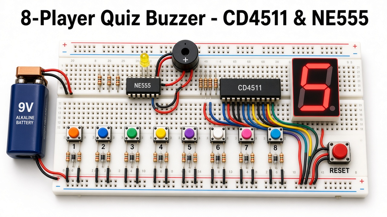
8-Player Quiz Buzzer with CD4511, 7-Segment Display & NE555 Beeper

8-player quiz buzzer on a breadboard with CD4511 decoder, red 7-segment display showing 5, NE555 timer, buzzer, eight numbered push buttons, reset button and 9V battery

Build an 8-player quiz buzzer with a CD4511 latch decoder, a 7-segment display and an NE555 beeper that shows who pressed first and locks everyone else out. No code needed.

  • DifficultyAdvanced
  • Build time5–8 hours
  • Board / MCUNo MCU (CD4511 + NE555)
  • Parts17 items
  • CodeNot needed

Need it ready-made? Buy Ready Project

This 8-player quiz buzzer is the classic school and college quiz-show gadget, built with just two everyday ICs and no microcontroller. Each player gets a button. The moment the first player presses, their number (1 to 8) appears on a big 7-segment display, a buzzer beeps for about a second, and every other button is ignored until the quiz master presses Reset.

The trick is the CD4511. Besides decoding BCD to 7-segment, it has a built-in latch. A small diode network turns each button into a BCD number, and the display itself feeds back into the latch pin, so the first number shown freezes on the display. An NE555 in monostable mode makes the beep. It runs from a 9V battery and needs no programming at all.

8-player quiz buzzer on a breadboard with CD4511 decoder, red 7-segment display showing 5, NE555 timer, buzzer, eight numbered push buttons, reset button and 9V battery

How It Works

  • Idle state is blank: the four BCD inputs of the CD4511 (A, B, C, D) are pulled up to +9V by 10 kΩ resistors, so the input is 1111 (decimal 15). The CD4511 blanks the display for any input above 9, so nothing is shown while everyone waits.
  • Diode matrix encodes the player: each player button connects to GND, and 1N4148 diodes run from the BCD lines to that button. Pressing a button pulls only the lines that should be 0 for that player number. For example, player 5 is binary 0101, so its button pulls B and D low through two diodes and the display shows 5. The diodes stop one button from affecting the lines used by the others.
  • The display locks itself: every digit from 1 to 9 lights segment b or segment c (or both), while the blank state lights neither. Two diodes take segments b and c to the Latch Enable pin (LE, pin 5) through 1 kΩ. As soon as a digit appears, LE goes high and the CD4511 latches that number. The latched digit keeps b or c lit, so LE stays high and the display holds even after the player lets go.
  • Everyone else is locked out: while LE is high the CD4511 ignores its inputs, so later presses change nothing. The lock happens within microseconds, so ties are practically impossible.
  • Reset: the reset button shorts LE to GND. The latch opens, the inputs are back at 1111, the display blanks, b and c go off, and LE stays low after you release the button. The 100 kΩ resistor keeps LE low while idle.
  • Beep: when LE goes high the BC547 turns on and its collector drops. The 10 nF capacitor turns that edge into a short low pulse on NE555 pin 2, which triggers a monostable. The 555 output (pin 3) then drives the buzzer and the yellow LED for t = 1.1 × 100 kΩ × 10 µF, about 1.1 seconds. The 1N4148 on pin 2 clips the positive spike when LE falls at reset.

Components Required

  • CD4511 BCD to 7-segment latch / decoder / driver IC (CD4511BE) – 1
  • NE555 timer IC – 1
  • Common-cathode 7-segment display, 0.56 inch red – 1
  • 1N4148 signal diodes – 22 (19 for the player matrix, 2 for the latch, 1 for the trigger clamp)
  • 1N4007 diode (reverse polarity protection) – 1
  • BC547 NPN transistor – 1
  • Push buttons – 9 (8 player buttons, big arcade-style ones are best, plus 1 reset button)
  • 10 kΩ resistors – 6
  • 100 kΩ resistors – 3
  • 1 kΩ resistors – 2
  • 680 Ω resistors – 7 (display segments)
  • 10 µF and 100 µF electrolytic capacitors – 1 each
  • 10 nF ceramic capacitors – 2
  • 100 nF ceramic capacitors – 2
  • Active buzzer, 3–24V type – 1
  • 5 mm yellow LED – 1
  • 9V battery with snap (or a 9V adapter), breadboard or perfboard, 16-pin and 8-pin IC sockets, long wires for the player buttons

Wiring Table

FromToNotes
9V battery (+)1N4007 anode1N4007 cathode is the +9V rail (reverse polarity protection)
+9V railCD4511 pin 16, NE555 pins 4 and 8100 µF + 100 nF across the rail near the ICs
GNDCD4511 pin 8, NE555 pin 1Common ground for everything
CD4511 pin 3 (LT) and pin 4 (BI)+9VBoth are active low, so tie them high
CD4511 pin 7 (A), 1 (B), 2 (C), 6 (D)+9V through 10 kΩ eachIdle input is 1111, display blank
Player diodes (1N4148)BCD line (anode) to player button (cathode)See the matrix table below
Every player button and the reset buttonGNDOther side of each button
CD4511 pins 13, 12, 11, 10, 9, 15, 14Display a, b, c, d, e, f, gEach through 680 Ω; display common cathode to GND
CD4511 pin 12 (b) and pin 11 (c)Two 1N4148 anodesCathodes joined, then 1 kΩ to CD4511 pin 5 (LE)
CD4511 pin 5 (LE)GND through 100 kΩ, and the reset button to GNDKeeps the latch open while idle
CD4511 pin 5 (LE)BC547 base through 100 kΩBC547 emitter to GND
BC547 collector+9V through 10 kΩ, and 10 nF to NE555 pin 2Turns LE going high into a trigger pulse
NE555 pin 2+9V through 10 kΩPlus a 1N4148 with cathode to +9V, anode to pin 2
NE555 pins 6 and 7 (joined)+9V through 100 kΩ, GND through 10 µFBeep length about 1.1 s
NE555 pin 5GND through 10 nFNoise filter
NE555 pin 3Buzzer (+), and yellow LED anode through 1 kΩBuzzer (-) and LED cathode to GND

Player Diode Matrix

Each tick is one 1N4148 diode with its anode on that BCD line and its cathode on that player’s button. A line with a diode is pulled to 0 when the button is pressed; a line without one stays at 1.

Player (BCD)A (pin 7)B (pin 1)C (pin 2)D (pin 6)Diodes
1 (0001)✔✔✔3
2 (0010)✔✔✔3
3 (0011)✔✔2
4 (0100)✔✔✔3
5 (0101)✔✔2
6 (0110)✔✔2
7 (0111)✔1
8 (1000)✔✔✔3
Total19

Connection Diagram

The illustration above shows how the parts sit on the breadboard. It is a layout guide only, and its wire colours and positions are not exact. Follow the pin-accurate drawing below, which matches the wiring tables.

8-Player Quiz Buzzer (CD4511 + NE555) – Pin-Accurate Wiring 9V supply 9V (+) through 1N4007 (anode at battery) to the +9V rail 100 µF + 100 nF across +9V and GND CD4511 pin 16 (VDD) and NE555 pins 4 and 8 to +9V CD4511 pin 8 (VSS) and NE555 pin 1 to GND CD4511 setup Pin 3 (LT) and pin 4 (BI) to +9V Pin 5 (LE) to GND through 100 kΩ 100 nF from pin 16 to pin 8 BCD inputs A pin 7, B pin 1, C pin 2, D pin 6 Each input to +9V through its own 10 kΩ Idle = 1111 so the display is blank Player matrix 19 × 1N4148: anode on a BCD line, cathode on a player button Other side of every player button to GND Diodes per player: see the matrix table Display a 13, b 12, c 11, d 10, e 9, f 15, g 14 Each through 680 Ω to the display segment Display common cathode to GND Latch feedback 1N4148 anodes on pin 12 (b) and pin 11 (c) Cathodes joined, then 1 kΩ to pin 5 (LE) Reset button from pin 5 (LE) to GND Beep trigger LE (pin 5) through 100 kΩ to BC547 base, emitter to GND Collector to +9V via 10 kΩ, and via 10 nF to NE555 pin 2 Pin 2 to +9V via 10 kΩ; 1N4148 clamp, cathode to +9V NE555 beeper Pins 6 and 7 joined: 100 kΩ to +9V, 10 µF to GND (about 1.1 s) Pin 5 to GND via 10 nF Pin 3 to buzzer (+) and via 1 kΩ to yellow LED; both to GND
Pin-accurate connection diagram for the 8-player quiz buzzer with CD4511 and NE555.

Code

No code is needed. The CD4511 and NE555 are fixed-function chips, so the circuit works as soon as it is wired and powered.

Testing

  • Build the 9V rail, the CD4511 and the display first, without the latch diodes. Temporarily ground pin 5 and press each player button: you should see 1 to 8, and a blank display when no button is pressed.
  • Add the two latch diodes and the 1 kΩ to pin 5. Now press player 3 and let go: 3 should stay on the display. Press any other button and nothing should change.
  • Press Reset. The display should go blank and stay blank.
  • Add the BC547 and the NE555 stage. Each new lock should give one beep of about a second and light the yellow LED. Reset should not beep.
  • Finally, run long twin wires to each player’s button and test from the far end of the table.

Troubleshooting

ProblemFix
Display shows 8 or a wrong digit at idleCheck all four 10 kΩ pull-ups on A, B, C, D, and that pins 3 and 4 are tied to +9V. Make sure the display is common cathode, not common anode.
A player shows the wrong numberA diode is missing or reversed in the matrix. The band (cathode) of every matrix diode must face the button.
Number disappears when the button is releasedThe latch feedback is not working. Check the two diodes on pins 12 and 11 (band towards LE) and the 1 kΩ to pin 5. A weak or old 9V battery can also keep LE below the logic-high level, so try a fresh one.
Display locks at power-onUsually a missing 100 kΩ from LE to GND. Press Reset once after switching on.
No beepCheck the 10 nF coupling capacitor to pin 2 and the 10 kΩ pull-up on pin 2. Make sure pin 4 of the 555 is at +9V and the buzzer is an active type that is polarity-correct.
Beeps all the timeThe 555 trigger is stuck low. Pin 2 must sit at +9V through 10 kΩ, and the BC547 collector must connect to pin 2 only through the 10 nF capacitor.
Two players pressed together show a strange digitThe lock takes microseconds, so true ties are very rare. If both buttons are held at the exact same moment, their diodes combine; simply press Reset and ask again.

Ideas to Extend

  • Add a second NE555 as a 10-second answer timer that starts when a player locks in.
  • Use a 2.3 inch large 7-segment display with a ULN2003 driver so the whole room can see it.
  • Expand to 9 players: player 9 (1001) needs diodes on B and C only.
  • Swap the active buzzer for a small speaker and a 555 astable tone for a louder game-show sound.

555 Timer PWM DC Motor Speed Controller with IRFZ44N

555 timer PWM DC motor speed controller on a breadboard with NE555, potentiometer, IRFZ44N MOSFET, flyback diode and 12V DC motor

Build a 555 timer PWM DC motor speed controller with an IRFZ44N MOSFET and a 100k knob. No code needed. Components list, wiring table, diagram and testing tips.

  • DifficultyIntermediate
  • Build time2–4 hours
  • Board / MCUNo MCU: NE555 timer
  • Parts11 items
  • CodeNot needed

Need it ready-made? Buy Ready Project

This 555 PWM motor speed controller lets you smoothly change the speed of a 12V DC motor, fan or pump with a single knob. Instead of wasting power in a big resistor, the NE555 timer switches the motor fully on and off about 1,400 times a second, and the knob changes how long each pulse stays on. An IRFZ44N MOSFET does the heavy switching, so the circuit can drive motors of a few amps with very little heat. No microcontroller and no code are needed.

It is a medium-level analog build that teaches pulse width modulation (PWM), the 555 astable mode with steering diodes, and how to drive a logic-level load with a MOSFET. The same board also works as a dimmer for 12V LED strips or as a speed control for a small drill, a cooler fan or a DC water pump.

555 timer PWM DC motor speed controller on a breadboard with NE555, potentiometer, IRFZ44N MOSFET, flyback diode and 12V DC motor

How It Works

  • Astable oscillator: the NE555 runs in astable mode. The 10 nF timing capacitor on pins 2 and 6 charges and discharges between one third and two thirds of the supply voltage, producing a square wave on pin 3.
  • Steering diodes: the capacitor charges through the 1k resistor, the left half of the 100k potentiometer and diode D1. It discharges through diode D2, the right half of the pot and pin 7. Turning the knob moves resistance from one path to the other, so the on-time and off-time change while their sum, and therefore the frequency, stays almost constant.
  • Duty cycle: with these values the duty cycle can be set from roughly 2% to 98%. The frequency is about f = 1.44 / ((1k + 100k) × 10 nF), close to 1.4 kHz.
  • MOSFET switch: pin 3 drives the gate of the IRFZ44N through a 100 Ω resistor. With a 12V supply the 555 output reaches about 10–11 V, which turns the MOSFET fully on. The 10k pull-down keeps the motor off while the circuit powers up.
  • Flyback diode: a motor is an inductor, so each time the MOSFET switches off it produces a voltage spike. The 1N5822 Schottky diode across the motor gives that energy a safe path and protects the MOSFET.
  • Average power: because the motor sees full voltage in short bursts, it keeps good torque even at low speed, which a simple series resistor cannot do.

Components Required

  • NE555 timer IC (DIP-8) with an 8-pin socket – 1
  • IRFZ44N N-channel MOSFET (TO-220) with a small heatsink – 1
  • 100k linear potentiometer (B100K) with knob – 1
  • 1N4148 small-signal diodes – 2
  • 1N5822 Schottky diode (3 A), or 1N5408 for slow motors – 1
  • Resistors: 1k – 1, 100 Ω – 1, 10k – 1
  • Capacitors: 10 nF ceramic – 2, 100 nF ceramic – 1, 100 µF 25 V electrolytic – 1
  • 12V DC motor, fan or pump (up to about 3 A for this layout)
  • 12V DC adapter (rated above the motor current) with DC jack
  • Fuse holder with a fuse slightly above the motor current (recommended)
  • Breadboard or perfboard, screw terminals and jumper wires

Wiring Table

Part / pinConnects toNotes
NE555 pin 8 (VCC)+12V100 nF and 100 µF from +12V to GND near the IC
NE555 pin 4 (RESET)+12VKeeps the timer running
NE555 pin 1 (GND)GND
1k resistor+12V and NE555 pin 7Sets the minimum charge resistance
NE555 pin 7 (DIS)Potentiometer wiper (middle pin)
Pot end A1N4148 D1 anodeD1 cathode (band) to pins 2 and 6
Pot end B1N4148 D2 cathode (band)D2 anode to pins 2 and 6
NE555 pins 2 and 6Joined togetherTrigger and threshold
10 nF capacitorPins 2/6 and GNDTiming capacitor (about 1.4 kHz)
10 nF capacitorPin 5 and GNDControl-voltage noise filter
NE555 pin 3 (OUT)100 Ω to IRFZ44N gateGate resistor
10k resistorIRFZ44N gate and GNDGate pull-down
IRFZ44N sourceGNDPins facing you, metal tab at back: gate, drain, source (left to right)
IRFZ44N drainMotor (-)Use thick wire for the motor path
Motor (+)+12V (through the fuse)
1N5822 diodeAcross the motorCathode (band) to +12V, anode to the drain

Connection Diagram

The illustration above shows a typical breadboard layout and is only a guide for placement. The pin-accurate drawing below matches the wiring table exactly, so follow it while you build.

555 PWM DC Motor Speed Controller – Pin-Accurate Wiring 12V supply +12V: NE555 pin 8 and pin 4, 1k resistor, motor (+), diode cathode GND: NE555 pin 1, 10 nF timing cap, 10 nF pin-5 cap, 10k gate resistor, IRFZ44N source 100 µF + 100 nF capacitors across +12V and GND near the 555 Charge path 1k resistor: +12V to NE555 pin 7 (discharge) NE555 pin 7 to 100k potentiometer wiper (middle pin) Pot end A to 1N4148 D1 anode; D1 cathode to pins 2 and 6 Discharge path Pot end B to 1N4148 D2 cathode; D2 anode to pins 2 and 6 NE555 pin 2 and pin 6 joined together Timing 10 nF capacitor: pins 2/6 to GND (about 1.4 kHz) 10 nF capacitor: pin 5 (control) to GND MOSFET driver NE555 pin 3 (output) through 100 Ω to IRFZ44N gate 10k resistor: IRFZ44N gate to GND (pull-down) IRFZ44N source to GND Motor Motor (+) to +12V, motor (-) to IRFZ44N drain 1N5822 diode across motor: cathode to +12V, anode to drain
Pin-accurate connection diagram for the 555 PWM DC motor speed controller.

Code

No code is needed. The NE555 is a fixed-function timer IC, so the controller works as soon as power is connected.

Testing and Adjustment

  • Before connecting the motor, power the board and measure pin 3 with a multimeter on DC volts. Turning the knob should move the reading smoothly from near 0 V to about 10 V (the meter shows the average).
  • Connect the motor and turn the knob slowly from minimum. Some motors only start at about 20–30% duty, then hold low speed fine once spinning.
  • If you hear a high-pitched whine, that is the 1.4 kHz PWM. Change the 10 nF timing capacitor on pins 2 and 6 to 1 nF (keep the 10 nF on pin 5) to move the frequency to about 14 kHz, above most people’s hearing.
  • Feel the MOSFET after a few minutes at half speed. It should be only warm. If it gets hot, add a bigger heatsink or check that the gate is really reaching 10 V.

Troubleshooting

ProblemFix
Motor runs at full speed all the timeCheck the MOSFET pin order (gate, drain, source) and that pin 3 is going to the gate, not the drain. A damaged IRFZ44N often fails shorted, so try a new one.
Motor never turnsCheck that pin 4 is tied to +12V and that the motor (-) goes to the drain. Measure pin 3: it should change with the knob.
Knob works backwardsSwap the two outer pins of the potentiometer.
555 resets or motor stuttersAdd more capacitance (220–470 µF) across the supply and keep motor wires away from the timer wiring. Make sure the flyback diode is fitted the right way round.
MOSFET gets very hotUse a heatsink, shorten the motor wires, and keep the supply at 12V so the gate gets a full 10 V. For motors above 3 A use a logic-level MOSFET like IRLZ44N with a heatsink.

Ideas to Extend

  • Add a DPDT toggle switch or a small relay to reverse the motor direction (only switch it when the motor is stopped).
  • Place a 7809 or 7812 regulator for the 555 and run the motor from 24V, keeping the motor supply and the timer supply grounds joined.
  • Replace the potentiometer with an LM35 and an LM358 stage for an automatic temperature-controlled fan.

LM358 Fire Alarm Circuit with Thermistor & Buzzer

LM358 fire alarm circuit on a breadboard with NTC thermistor, 10k preset, BC547 transistor, buzzer, LEDs and 9V battery

Build a simple LM358 fire alarm circuit with a 10k NTC thermistor, preset, BC547 and buzzer. No microcontroller or code needed. Components list, wiring table, diagram and setup steps.

  • DifficultyEasy
  • Build time1–2 hours
  • Board / MCUNo MCU: LM358 op-amp
  • Parts10 items
  • CodeNot needed

Need it ready-made? Buy Ready Project

This LM358 fire alarm circuit sounds a loud buzzer and lights a red LED when the temperature near a small NTC thermistor rises above a level you set with a preset. It needs no microcontroller and no code: one LM358 op-amp works as a comparator, and a BC547 transistor drives the alarm. The whole circuit fits on a small breadboard and runs from a 9V battery.

It is a good small analog project for learning how a comparator, a voltage divider and a transistor switch work together. Place the thermistor near a stove, a battery charger, an electrical panel or inside a small cabinet to get an early warning of overheating. It is a learning project, not a replacement for a certified smoke detector.

LM358 fire alarm circuit on a breadboard with NTC thermistor, 10k preset, BC547 transistor, buzzer, LEDs and 9V battery

How It Works

  • Heat sensor: the 10k NTC thermistor and a fixed 10k resistor form a voltage divider. An NTC’s resistance falls as it gets hotter, so the voltage at the LM358’s non-inverting input (pin 3) rises with temperature. At 25 °C it sits at about half the supply, around 4.5 V.
  • Set-point: the 10k preset gives an adjustable reference voltage to the inverting input (pin 2). Turning it sets the temperature at which the alarm trips.
  • Comparator: while pin 3 is below pin 2, the LM358 output (pin 1) stays low and everything is quiet. When heat pushes pin 3 above pin 2, the output swings high, to about 7.5 V on a 9V supply.
  • Hysteresis: a 1 MΩ resistor from the output back to pin 3 adds a little positive feedback, so the alarm switches cleanly instead of chattering when the temperature hovers right at the set-point.
  • Alarm driver: the high output turns on the BC547 through a 1k base resistor. The transistor connects the buzzer and the red LED to ground, so both turn on. The green LED simply shows that power is on.
  • Unused half: the LM358 has two op-amps. The second one (pins 5, 6 and 7) is not used; tie pin 5 to GND and pin 6 to pin 7 to keep it quiet.

Components Required

  • LM358 dual op-amp IC (DIP-8) with an 8-pin socket – 1
  • 10k NTC thermistor (bead type) – 1
  • 10k preset (trimmer potentiometer) – 1
  • BC547 NPN transistor – 1
  • Active buzzer, 3–24 V type – 1
  • 5 mm red LED and 5 mm green LED – 1 each
  • Resistors: 10k – 1, 1k – 3, 1 MΩ – 1
  • 100 nF ceramic capacitor – 1
  • 9V battery with snap connector (or a 9–12 V DC adapter)
  • Breadboard and jumper wires

Wiring Table

Part / pinConnects toNotes
LM358 pin 8 (VCC)+9V100 nF capacitor from pin 8 to pin 4, close to the IC
LM358 pin 4 (GND)GND
NTC thermistor+9V and LM358 pin 3Either way round
10k resistorLM358 pin 3 and GNDLower half of the sensor divider
10k preset ends+9V and GND
10k preset wiperLM358 pin 2Sets the trip temperature
1 MΩ resistorLM358 pin 1 and pin 3Hysteresis (clean switching)
1k resistorLM358 pin 1 and BC547 baseBase current limit
BC547 emitterGNDFlat face toward you: collector, base, emitter (left to right)
Active buzzer (+)+9VLonger leg or + mark
Active buzzer (-)BC547 collector
Red LED anode via 1k+9VCathode to BC547 collector
Green LED anode via 1k+9VCathode to GND (power indicator)
LM358 pin 5 / pins 6 and 7GND / tied togetherUnused second op-amp

Connection Diagram

The illustration above shows a typical breadboard layout; its pin labels are only for orientation. The pin-accurate drawing below matches the wiring table exactly, so follow it while building.

LM358 Fire Alarm – Pin-Accurate Wiring 9V supply +9V: LM358 pin 8, NTC top, preset top, buzzer (+), LED resistors GND: LM358 pin 4, 10k resistor, preset bottom, BC547 emitter 100 nF capacitor across pin 8 and pin 4 Sensor divider NTC 10k: +9V to LM358 pin 3 (non-inverting input) 10k resistor: pin 3 to GND (pin 3 voltage rises with heat) Set-point 10k preset: ends to +9V and GND Wiper to LM358 pin 2 (inverting input) Hysteresis 1 MΩ resistor from LM358 pin 1 (output) to pin 3 Driver LM358 pin 1 through 1k to BC547 base BC547 emitter to GND, collector to alarm (-) side Alarm Active buzzer: (+) to +9V, (-) to BC547 collector Red LED + 1k: +9V to BC547 collector (in parallel) Green power LED + 1k: +9V to GND
Pin-accurate connection diagram for the LM358 fire alarm circuit.

Code

No code is needed. This is a purely analog circuit built around the LM358 comparator, so it works as soon as it is powered.

Setting the Trip Temperature

  • Power the circuit at room temperature. If the buzzer is on, turn the preset slowly until it just goes off.
  • Warm the thermistor with your fingers or a hair dryer on low. The buzzer should sound after a few seconds.
  • For a higher trip point, turn the preset a little further past the switching point so pin 2 sits higher than pin 3 at room temperature. A multimeter helps: pin 3 is about 4.5 V at 25 °C and about 7 V near 60 °C with a typical 10k NTC (B = 3950).
  • Let the thermistor cool. The alarm stops on its own once the temperature drops a few degrees below the trip point.

Troubleshooting

ProblemFix
Buzzer is always onTurn the preset the other way, and check that the NTC goes to pin 3 and the preset wiper to pin 2, not the other way round.
Buzzer never soundsCheck the BC547 pin order and that the buzzer is an active type (it beeps on DC). A passive buzzer stays silent.
Alarm chatters near the set-pointMake sure the 1 MΩ hysteresis resistor is fitted between pin 1 and pin 3. A lower value such as 470k gives a wider gap.
Works on the bench but triggers randomlyKeep the thermistor leads short or use twisted wire, and fit the 100 nF capacitor right at the IC.
Battery drains quicklyThe circuit draws a few milliamps at idle. Remove the green LED or use a 9–12 V adapter for permanent use.

Ideas to Extend

  • Replace the buzzer with a 5V or 12V relay module (with a 1N4007 diode across the coil) to switch off a heater or start an exhaust fan.
  • Add an LDR divider on the unused second op-amp to also detect the bright light of a flame.
  • Use a 7805 regulator and a small solar panel with a rechargeable battery for an off-grid shed alarm.

IR Object Counter 00-99 with LM358, NE555 & CD4026

IR object counter 00-99 breadboard wiring with 7805, LM358, NE555, two CD4026 and two 7-segment displays

Build an IR object counter that counts from 00 to 99 using a 7805, LM358, NE555 and two CD4026 chips. No code, full wiring table and diagram.

  • DifficultyAdvanced
  • Build time5–8 hours
  • Board / MCUNo MCU: LM358 + NE555 + CD4026
  • Parts13 items
  • CodeNot needed

Need it ready-made? Buy Ready Project

This IR object counter counts things that pass in front of an infrared sensor and shows the total from 00 to 99 on two 7-segment displays. It is built only from common ICs: a 7805 regulator, an LM358 comparator, an NE555 timer and two CD4026 counter/display driver chips. There is no microcontroller and no code to upload.

Use it to count people entering a room, boxes on a small conveyor, laps of a toy car or products on a packing table. A reset button clears the count back to 00.

IR object counter 00-99 breadboard wiring with 7805, LM358, NE555, two CD4026 and two 7-segment displays

How It Works

  • Power: the 7805 turns a 9 V battery or adapter into a steady 5 V for every chip.
  • IR sensor: the IR LED shines forward. When an object passes close to the sensor, IR light reflects back into the photodiode, the photodiode lets more current flow, and the voltage at the sense node (across the 10 kΩ resistor) rises.
  • LM358 comparator: the sense voltage goes to the inverting input (pin 2) and the 10 kΩ pot sets a reference on the non-inverting input (pin 3). When an object is present, pin 2 is higher than pin 3 and the output (pin 1) goes LOW.
  • NE555 one-shot: that LOW edge triggers the 555 in monostable mode. It gives one clean HIGH pulse of about 1.1 × 10 kΩ × 10 µF = 0.11 s, which removes the jitter and false double counts you get from a raw sensor.
  • CD4026 units counter: each rising edge on its clock pin (pin 1) adds one. The chip has its own 7-segment decoder, so it drives a common-cathode display directly through 220 Ω resistors.
  • CD4026 tens counter: when the units digit rolls from 9 to 0, its CARRY OUT (pin 5) gives a rising edge that clocks the second CD4026, so the display counts 00 to 99 and then starts again.
  • Reset: pressing the button pulls both RESET pins (pin 15) HIGH and the count goes back to 00. A 10 kΩ resistor keeps RESET LOW the rest of the time.

Components Required

  • 7805 5 V voltage regulator – 1
  • LM358 dual op-amp – 1
  • NE555 timer IC – 1
  • CD4026 decade counter / 7-segment driver – 2
  • Common-cathode 7-segment display (0.56 inch) – 2
  • IR LED (5 mm, 940 nm) – 1
  • IR photodiode (5 mm, black) – 1
  • 10 kΩ trimmer potentiometer – 1
  • Resistors: 220 Ω – 15 (14 segments + IR LED), 10 kΩ – 3
  • Capacitors: 10 µF electrolytic – 2, 100 nF ceramic – 1, 10 nF ceramic – 1
  • Push button (reset) – 1
  • 9 V battery with snap, or 9–12 V DC adapter
  • Breadboard or perfboard, jumper wires

Wiring Table

FromToNotes
9 V battery +7805 pin 1 (IN)10 µF from pin 1 to GND
9 V battery –7805 pin 2 (GND)Common ground for the whole circuit
7805 pin 3 (OUT)+5 V rail100 nF from pin 3 to GND
+5 VIR LED anode through 220 ΩIR LED cathode to GND
+5 VPhotodiode cathode (short leg)Photodiode is reverse-biased
Photodiode anodeLM358 pin 2 (IN1–)Also 10 kΩ from this node to GND
10 kΩ pot wiperLM358 pin 3 (IN1+)Pot ends to +5 V and GND; sets sensitivity
LM358 pin 8 / pin 4+5 V / GNDOp-amp power
LM358 pin 1 (OUT1)NE555 pin 2 (TRIG)Goes LOW when an object is seen
NE555 pins 4 and 8+5 VReset held HIGH, power
NE555 pin 1GND
NE555 pins 6 and 710 kΩ to +5 V, 10 µF to GNDPulse width about 0.11 s
NE555 pin 510 nF to GNDNoise filter
NE555 pin 3 (OUT)CD4026 #1 pin 1 (CLK)Units counter clock
CD4026 #1 pin 5 (CARRY OUT)CD4026 #2 pin 1 (CLK)Tens counter clock
CD4026 pins 16 and 3 (both)+5 VVDD and Display Enable In
CD4026 pins 8 and 2 (both)GNDVSS and Clock Inhibit
CD4026 pin 15 (both)10 kΩ to GND, button to +5 VReset to 00
CD4026 pins 10, 12, 13, 9, 11, 6, 7Display segments a, b, c, d, e, f, gEach through a 220 Ω resistor
Display common pin (both)GNDCommon-cathode type only

Connection Diagram

The illustration above shows the general breadboard layout. The pin-accurate drawing below matches the wiring table exactly, so follow it when you build the circuit.

IR Object Counter 00-99 – Pin-Accurate Wiring 7805 Regulator Pin 1 IN: 9 V battery +, 10 µF to GND Pin 2 GND: battery – and common GND Pin 3 OUT: +5 V rail, 100 nF to GND IR Sensor + LM358 IR LED: +5 V, 220 Ω, anode; cathode to GND Photodiode: cathode to +5 V, anode to SENSE node SENSE node: 10 kΩ to GND and LM358 pin 2 10 kΩ pot: ends +5 V / GND, wiper to LM358 pin 3 LM358 pin 8 = +5 V, pin 4 = GND, pin 1 = OUT NE555 Monostable Pin 2 TRIG: LM358 pin 1 Pins 4 and 8: +5 V; pin 1: GND Pins 6 and 7: joined, 10 kΩ to +5 V, 10 µF to GND Pin 5: 10 nF to GND Pin 3 OUT: CD4026 (units) pin 1 CLK CD4026 x2 + Displays Pin 16 VDD and pin 3 DEI: +5 V; pin 8 VSS and pin 2 INH: GND Segments via 220 Ω: a=10, b=12, c=13, d=9, e=11, f=6, g=7 Units pin 5 CARRY OUT to tens pin 1 CLK Both pin 15 RESET: 10 kΩ to GND, RESET button to +5 V Display common cathode to GND Signal flow: IR sensor, LM358 comparator, 555 one-shot pulse, units CD4026, carry to tens CD4026.
Pin-accurate connection diagram for the IR object counter 00-99.

Code

No code is needed. Every part of this project is a fixed-function IC, so it works as soon as it is wired and powered.

Setting Up and Testing

  • Power the circuit. Both displays should show 00 (press RESET if they show something else).
  • Mount the IR LED and photodiode side by side, about 5 mm apart, both facing the same way. A small black tube around the photodiode helps block room light.
  • Hold your hand about 3–5 cm in front of the sensor and turn the pot slowly until the count goes up by one each time you move your hand in.
  • Move your hand away and back ten times. The units digit should go 1 to 9 and then 0 while the tens digit shows 1.
  • Press RESET and check that the display returns to 00.

Troubleshooting

ProblemFix
Count jumps by 2 or 3 for one objectIncrease the 555 timing capacitor to 22 µF, or shade the photodiode from sunlight and lamps.
Nothing countsAdjust the pot through its whole range and check that the photodiode short leg goes to +5 V.
Count keeps rising with nothing thereThe reference is set too low; turn the pot the other way until it stops.
Wrong digits or missing segmentsCheck each segment line against the table and confirm the display is common cathode.
Tens digit never changesCheck the wire from CD4026 #1 pin 5 to CD4026 #2 pin 1.

Ideas to Extend

  • Add a third CD4026 and display to count up to 999.
  • Use a break-beam setup (IR LED facing the photodiode across a doorway) for longer range.
  • Add a small buzzer on the 555 output so you hear a beep for every count.

CD4060 Delay-Off Timer with Relay (3 to 34 Minutes)

CD4060 delay-off timer with relay on a breadboard, with potentiometer, START button and 12V adapter

Build a CD4060 delay-off timer that turns a relay on at the press of a button and switches it off after 3 to 34 minutes. Components, how it works, wiring table and diagram. No code needed.

  • DifficultyIntermediate
  • Build time2–4 hours
  • Board / MCUNo MCU: CD4060 IC
  • Parts11 items
  • CodeNot needed

Need it ready-made? Buy Ready Project

This CD4060 delay-off timer switches a relay ON the moment you press START, keeps it on for a time you set with a knob (about 3 to 34 minutes), and then switches it OFF by itself. It is perfect for a bathroom exhaust fan, a water heater, a phone charger, a soldering iron or any load you often forget to turn off.

The whole circuit uses one CD4060 counter/oscillator IC, one transistor and a relay. There is no microcontroller and no code to upload, so it is a nice medium-level project for learning how a binary counter can make very long, stable delays with small parts.

CD4060 delay-off timer with relay on a breadboard, with potentiometer, START button and 12V adapter

How the CD4060 Delay Timer Works

  • Built-in oscillator: the CD4060 has an RC oscillator on pins 9, 10 and 11. With a 1 µF film capacitor and 10 kΩ plus a 100 kΩ pot, it runs at roughly 43 Hz down to 4 Hz. The frequency is about f = 1 / (2.3 × R × C).
  • 14-stage counter: the oscillator drives a binary counter inside the chip. Output Q14 (pin 3) goes HIGH after 8192 oscillator cycles, so the delay is T ≈ 8192 × 2.3 × R × C.
  • Start / reset: pressing START pulls the Master Reset pin (12) HIGH for a moment. All outputs go LOW and counting starts from zero. A 100 nF capacitor from pin 12 to +12 V also gives a short reset pulse at power-on, so the timer starts on its own when you plug it in.
  • Relay ON while timing: Q14 is LOW during the delay, which pulls the base of the BC557 PNP transistor low through 4.7 kΩ. The transistor conducts and energises the relay.
  • Relay OFF and latch: when Q14 goes HIGH the transistor turns off and the relay drops out. The 1N4148 diode from pin 3 to pin 11 now holds the oscillator input HIGH, so the clock stops and the circuit stays OFF until you press START again. The green DONE LED shows this state.
  • Safe relay switching: a 1N4007 diode across the relay coil absorbs the voltage spike when the coil turns off, protecting the transistor.

Delay Time Table

Pot settingTotal R (10 kΩ + pot)Approx. delay with 1 µF
Minimum10 kΩabout 3 minutes
One quarter35 kΩabout 11 minutes
Half60 kΩabout 19 minutes
Three quarters85 kΩabout 27 minutes
Maximum110 kΩabout 34 minutes

These values are calculated from the formula and real circuits vary by about ±15% because of capacitor tolerance. For longer delays use a 2.2 µF film capacitor (about 7 to 76 minutes). For shorter delays take the output from Q12 (pin 1) instead, which is four times faster.

Components Required

  • CD4060B 14-stage binary counter / oscillator IC (DIP-16) – 1, with a 16-pin IC socket
  • 1 µF polyester / MKT film capacitor (non-polarised, low leakage) – 1
  • 100 kΩ linear potentiometer – 1
  • Resistors: 10 kΩ, 1 MΩ, 100 kΩ and 4.7 kΩ – 1 each, plus 1 kΩ – 2
  • BC557 PNP transistor – 1
  • 1N4148 signal diode – 1 and 1N4007 diode – 1
  • 12 V SPDT relay (coil about 400 Ω), contacts rated for your load – 1
  • Push button (START) – 1
  • 100 nF ceramic capacitors – 2 and 100 µF/25 V electrolytic capacitor – 1
  • Green LED (DONE) and red LED (timing) – 1 each
  • 12 V DC adapter (500 mA), perfboard, screw terminals and wires

Wiring Table (Pin-to-Pin)

FromToNotes
CD4060 pin 16 (VDD)+12 V100 nF + 100 µF from +12 V to GND, close to the IC
CD4060 pin 8 (VSS)GNDCommon ground
CD4060 pin 9 (φO)RC nodeThrough the 1 µF film capacitor
CD4060 pin 10 (φO̅)RC nodeThrough 10 kΩ in series with the 100 kΩ pot (wired as a variable resistor)
CD4060 pin 11 (φI)RC nodeThrough the 1 MΩ resistor
CD4060 pin 12 (MR)GND100 kΩ pull-down resistor
CD4060 pin 12 (MR)+12 VSTART push button, and a 100 nF capacitor in parallel (power-on reset)
CD4060 pin 3 (Q14)BC557 baseThrough 4.7 kΩ
CD4060 pin 3 (Q14)CD4060 pin 111N4148: anode to pin 3, cathode to pin 11 (stops the clock when done)
CD4060 pin 3 (Q14)GND1 kΩ in series with the green DONE LED (anode towards pin 3)
BC557 emitter+12 V–
BC557 collectorRelay coil terminal 1Other coil terminal to GND
1N4007Across relay coilCathode (band) to the collector side, anode to GND
Red timing LEDAcross relay coilThrough 1 kΩ, anode to the collector side
Relay COM and NOLoadLoad is ON only during the delay
Pins 1, 2, 4, 5, 6, 7, 13, 14, 15–Outputs, leave unconnected

Connection Diagram

The pin-accurate drawing below matches the wiring table exactly. The illustration at the top of the post shows the general breadboard layout, while this drawing shows every pin.

CD4060 Delay-Off Timer – Pin-Accurate Wiring CD4060 1 Q12 n/c 2 Q13 n/c 3 Q14 4.7 kΩ to BC557 base; 1N4148 anode; DONE LED via 1 kΩ 4 Q6 n/c 5 Q5 n/c 6 Q7 n/c 7 Q4 n/c 8 VSS GND VDD 16 +12 V (100 nF + 100 µF to GND) Q10 15 n/c Q8 14 n/c Q9 13 n/c MR 12 100 kΩ to GND; 100 nF and START button to +12 V φI 11 1 MΩ to RC node; 1N4148 cathode φO̅ 10 10 kΩ + 100 kΩ pot to RC node φO 9 1 µF film capacitor to RC node Relay driver: BC557 emitter to +12 V, collector to relay coil, other coil end to GND, 1N4007 across the coil. Timing: T = 8192 × 2.3 × (10 kΩ + pot) × 1 µF ≈ 3 to 34 minutes. Relay is ON while timing and OFF when Q14 goes HIGH. All three timing parts (1 MΩ, 1 µF, 10 kΩ + pot) meet at one common RC node. Pins marked n/c are left unconnected.
Pin-accurate connection diagram for the CD4060 delay-off timer.

Code

No code is needed. The CD4060 is a fixed-function CMOS chip, so the delay is set completely by the resistor, potentiometer and capacitor values.

Building and Testing Tips

  • Test first with a 100 nF capacitor in place of the 1 µF. The delay becomes about 20 seconds to 3.5 minutes, which makes checking the circuit much faster.
  • Always use a film capacitor for timing. Electrolytic capacitors leak and make the delay long and unpredictable.
  • Keep the timing parts short and close to pins 9, 10 and 11 to avoid noise.
  • Measure pin 3 with a multimeter: it should read about 0 V while timing and about 12 V when finished.
  • If the relay contacts switch mains (230 V), use a relay rated for the load, keep mains wiring away from the low-voltage side, put the board in a closed plastic box and get help from a qualified electrician.

Troubleshooting

ProblemFix
Relay never turns onCheck the BC557 pinout (E-B-C) and that the emitter goes to +12 V, not GND. Press START and confirm pin 12 goes HIGH.
Relay stays on foreverThe oscillator is not running. Check the 1 MΩ, 1 µF and pot connections to pins 9, 10 and 11, and that pin 12 returns LOW (100 kΩ pull-down).
Timer restarts by itselfPin 12 is floating or picking up noise. Make sure the 100 kΩ resistor goes to GND and the supply has the 100 µF capacitor.
Delay is much longer than the tableYou may be using an electrolytic capacitor or a log pot. Use a film capacitor and a linear pot.
Timer does not start at power-onAdd or check the 100 nF capacitor from pin 12 to +12 V.

Ideas to Extend

  • Make it a delay-ON timer by using an NPN transistor (BC547) on Q14 so the relay turns ON after the delay instead of OFF.
  • Add a rotary switch to pick Q12, Q13 or Q14 for three delay ranges.
  • Use a 7805 and a 5 V relay to run the timer from a USB power bank.
  • Add a buzzer on Q14 so it beeps when the time is over, like a kitchen timer.

FAQ

What is the maximum supply voltage for the CD4060? The CD4060B works from 3 V to 15 V in normal use (18 V absolute maximum), so a 12 V adapter is ideal.

Why does pin 3 give 8192 cycles and not 16384? Q14 is the 14th counter stage, so it changes state every 2^13 = 8192 input pulses. After 8192 pulses it goes HIGH for the first time, which is the moment the timer finishes.

Can I get hours of delay? Yes. With a 4.7 µF film capacitor and a 220 kΩ pot the delay reaches more than 5 hours, but film capacitors that large are bulky, so a 2.2 µF part is a good balance.

555 Timer & CD4017 LED Chaser Circuit with 10 LEDs

Illustrated wiring overview of a 555 timer and CD4017 decade counter LED chaser with ten LEDs on a breadboard powered by a 9V battery

Build a 10-LED running light with a 555 timer and a CD4017 decade counter. No code needed: wiring table, pin-accurate diagram and speed calculation included.

  • DifficultyEasy
  • Build time1–2 hours
  • Board / MCUNo MCU: NE555 + CD4017
  • Parts11 items
  • CodeNot needed

Need it ready-made? Buy Ready Project

This CD4017 LED chaser makes ten LEDs light up one after another in a running pattern, like the lights on a festival decoration or a shop sign. It uses just two classic ICs: an NE555 timer that produces a steady stream of clock pulses, and a CD4017 decade counter that moves a single lit LED along each time a pulse arrives.

It is a small, beginner-friendly project with no microcontroller and no code. Everything is set by resistors and a capacitor, and a potentiometer lets you change the chasing speed from a slow crawl to a fast blur. It is a great first circuit for learning how timers and counters work together.

How the LED Chaser Works

  • The clock (NE555): the 555 is wired in astable mode. Capacitor C1 charges through R1 and R2 and discharges through R2 into pin 7, again and again. Each cycle gives one square-wave pulse on pin 3.
  • Speed control: the frequency is about f = 1.44 / ((R1 + 2 × R2) × C1). With R1 = 10 kΩ, C1 = 10 µF and R2 = 1 kΩ plus a 100 kΩ pot, the speed ranges from about 0.7 steps per second (pot at maximum) to about 12 steps per second (pot at minimum). The fixed 1 kΩ stops R2 ever reaching zero.
  • The counter (CD4017): on every rising edge at its CLOCK pin 14, the 4017 moves its single HIGH output to the next one, from Q0 to Q9. After Q9 it wraps back to Q0, so the pattern repeats forever.
  • The LEDs: each output drives one LED. Because only one output is HIGH at a time, all ten LEDs can share one current-limiting resistor (R3) on their common cathode line.
  • Always-on pins: RESET (pin 15) and CLOCK INHIBIT (pin 13) are tied to GND so the counter runs freely. The CARRY OUT pin 12 is not needed here.

Components Required

  • NE555 timer IC (8-pin DIP) – 1
  • CD4017 decade counter IC (16-pin DIP) – 1
  • 5 mm red LEDs – 10 (any colour works)
  • R1: 10 kΩ resistor – 1
  • R2: 1 kΩ resistor – 1, plus a 100 kΩ potentiometer – 1
  • R3: 470 Ω resistor – 1
  • C1: 10 µF 16 V electrolytic capacitor – 1
  • 10 nF ceramic capacitor (for 555 pin 5) – 1
  • 100 nF ceramic capacitor (decoupling for the 4017) – 1
  • 9 V battery with snap connector (any 5–12 V DC supply works)
  • Breadboard and jumper wires

Wiring Table (Pin-to-Pin)

PartPin / LeadConnects ToNotes
NE555Pin 8 (VCC)+9 V
NE555Pin 4 (RESET)+9 VKeeps the timer running
NE555Pin 1 (GND)GND
R1 10 kΩBetween+9 V and 555 pin 7
R2 1 kΩ + 100 kΩ potIn series between555 pin 7 and 555 pin 6Use the pot’s middle pin and one end pin
NE555Pin 6 (THR) and pin 2 (TRIG)Joined togetherShort jumper
C1 10 µF+ / −555 pin 6/2 / GNDMind the polarity
10 nF capacitorBetween555 pin 5 and GNDNoise filter on CTRL
NE555Pin 3 (OUT)CD4017 pin 14 (CLOCK)The clock signal
CD4017Pin 16 (VDD)+9 V
CD4017Pin 8 (VSS)GND
CD4017Pin 15 (RESET)GNDMust not float
CD4017Pin 13 (CLOCK INHIBIT)GNDMust not float
100 nF capacitorBetweenCD4017 pin 16 and pin 8Place close to the IC
CD4017 outputsQ0–Q9 = pins 3, 2, 4, 7, 10, 1, 5, 6, 9, 11LED1–LED10 anodes (long leg)In this order for a smooth chase
All LEDsCathodes (short leg)Joined, then R3 470 Ω to GNDOnly one LED is on at a time
CD4017Pin 12 (CARRY OUT)Not connected

Connection Diagram

The illustration below is also the featured image and shows the general layout on a breadboard. The labels in an illustration can be hard to read, so follow the pin-accurate drawing under it, which matches the wiring table, when you place the wires.

Illustrated wiring overview of a 555 timer and CD4017 decade counter LED chaser with ten LEDs on a breadboard powered by a 9V battery
LED chaser overview: 9 V battery, NE555 clock on a breadboard, CD4017 counter and ten LEDs.
555 Timer & CD4017 LED Chaser – Pin-Accurate Wiring +9 V rail (battery +) GND rail (battery −) NE555 1 GND 8 VCC 2 TRIG 7 DIS 3 OUT 6 THR 4 RESET 5 CTRL R1 10 kΩ: +9 V → pin 7 R2 1 kΩ + 100 kΩ pot: pin 7 → pins 6 & 2 C1 10 µF: pins 6/2 → GND (− to GND) Pin 4 → +9 V, Pin 8 → +9 V Pin 1 → GND, Pin 5 → 10 nF → GND 555 pin 3 → 4017 pin 14 CD4017 16 VDD → +9 V 8 VSS → GND 15 RESET → GND 13 INHIBIT → GND 14 CLOCK ← 555 12 CARRY (n.c.) Q0 pin 3 LED1 Q1 pin 2 LED2 Q2 pin 4 LED3 Q3 pin 7 LED4 Q4 pin 10 LED5 Q5 pin 1 LED6 Q6 pin 5 LED7 Q7 pin 6 LED8 Q8 pin 9 LED9 Q9 pin 11 LED10 R3 470 Ω All LED cathodes joined → R3 → GND C2 100 nF across pin 16 and pin 8
Pin-accurate connection diagram for the 555 timer and CD4017 LED chaser.

Code

None needed. This project uses only non-programmable logic ICs, so there is nothing to upload. The 555’s resistor and capacitor values set the timing, and the CD4017’s internal counter sets the sequence.

Building and Testing

  1. Place both ICs across the middle gap of the breadboard with their notches facing the same way. Pin 1 is to the left of the notch.
  2. Wire the power rails first: 555 pins 8 and 4 and 4017 pin 16 to +9 V; 555 pin 1 and 4017 pins 8, 13 and 15 to GND.
  3. Build the 555 timing network (R1, R2 with the pot, C1 and the 10 nF capacitor), then link 555 pin 3 to 4017 pin 14.
  4. Insert the ten LEDs with their long legs on Q0–Q9 in the order shown in the table, and join all short legs to R3, then to GND.
  5. Connect the battery. The LEDs should start running. Turn the pot to change the speed.

Troubleshooting

ProblemFix
No LED lights at allCheck battery polarity and the GND link of R3. Make sure 4017 pin 15 (RESET) is on GND, not left floating.
One LED stays on and nothing movesThe clock is missing. Check that 555 pin 4 is on +9 V, pins 2 and 6 are joined, and C1 is the right way round.
LEDs flicker randomly or skipPin 13 or 15 of the 4017 may be floating. Tie both to GND and add the 100 nF decoupling capacitor.
The chase jumps around instead of running in orderThe LEDs are in the wrong order. Remember the 4017 output pins are not sequential: 3, 2, 4, 7, 10, 1, 5, 6, 9, 11.
Too fast or too slowChange C1: 22 µF makes it about twice as slow, 4.7 µF about twice as fast.
LEDs are dimThe 4017 can only source a few milliamps. For bright LEDs or LED strips, drive each output through a ULN2003 or an NPN transistor.

Ideas to Extend This Project

  • Use fewer LEDs: connect the output after the last LED you want (for example Q5 for five LEDs) to pin 15 (RESET) to make the 4017 restart early.
  • Chain two CD4017s using CARRY OUT (pin 12) for longer, more complex patterns.
  • Replace the pot with an LDR so the chase speeds up in the dark.
  • Drive 12 V LED strips or bulbs through a ULN2003 for a real decoration light.

FAQ

Can I run it from 5 V USB power? Yes. Both the NE555 and the CD4017 work from 5 V. The timing stays the same, and with a 220 Ω R3 the LEDs stay bright.

Why do all LEDs share one resistor? The CD4017 turns on only one output at a time, so only one LED carries current at any moment. One resistor in the common cathode line is enough.

Can I use a CD4017 from any brand? Yes. CD4017BE, HEF4017 and MC14017 are all pin-compatible.

Related Projects

Browse more Timer IC/Analog on Arduino Project Hub.

Automatic Water Tank Controller with LM358, 555 & ULN2003

Connection diagram of an automatic water tank controller using LM358, NE555, ULN2003 and 7805 ICs with tank probes, pump relay and overflow buzzer

Build an automatic overhead water tank controller with LM358, 555, ULN2003 and 7805. No microcontroller or code: probe wiring, pump latch, overflow alarm and diagram.

  • DifficultyAdvanced
  • Build time5–8 hours
  • Board / MCUNo MCU: LM358 + NE555
  • Parts16 items
  • CodeNot needed

Need it ready-made? Buy Ready Project

This automatic water tank controller fills an overhead tank and switches the pump off when the water reaches the high probe. It is built from four everyday non-programmable ICs — a 7805 regulator, an LM358 dual op-amp, a NE555 timer and a ULN2003A Darlington array — so there is no microcontroller and no code to upload. Two transistors form a set-reset latch: the pump starts when the tank falls below the low probe and keeps running until the high probe gets wet. A fourth overflow probe enables the 555, which sounds a buzzer if the tank ever overfills.

Build and test it with a 12 V DC water pump (an aquarium or diaphragm pump is ideal). That keeps the whole project on low voltage. If you later switch a 230 V mains pump, use a properly rated enclosed relay or contactor and have the mains wiring done by a qualified person. Never put mains voltages on a breadboard.

Below you get a clear description of how the latch and alarm work, the full parts list, a pin-to-pin wiring table, and a connection diagram. Because every chip here is analog or a simple logic array, this project has no sketch to copy.

How the Water Tank Controller Works

A 12 V DC adapter powers the pump relay and the ULN2003 clamp pin. The same 12 V goes into a 7805, which makes a clean 5 V rail for the LM358 and the 555. Put a 10 µF electrolytic and a 0.1 µF ceramic capacitor on both the regulator input and the output, close to the 7805 pins.

Four stainless steel probes hang in the tank. The COM probe sits at the bottom and is wired to +5 V. The LOW, HIGH and OVERFLOW probes sit at about 20 percent, 90 percent and just above the high mark. Each sense probe has a 100 kΩ resistor to ground. When water touches a probe, it conducts from COM and the probe voltage rises well above the 2.5 V reference (two 10 kΩ resistors between +5 V and ground).

Inside the LM358, op-amp A compares the HIGH probe (pin 3) with 2.5 V (pin 2). Pin 1 goes high when the tank is full. Op-amp B compares the LOW probe (pin 5) with 2.5 V (pin 6). Pin 7 goes high when water is at or above the low probe.

The pump must not chatter every time the water ripples around one probe. That is what the latch is for:

  • Start: when the tank is below LOW, pin 7 is low. Transistor Q1 inverts that signal, so START is high. Diode D1 pulls the RUN node high and the pump turns on.
  • Hold: once the relay closes, its normally-open contact feeds 12 V into a 15 kΩ + 10 kΩ divider (about 4.8 V). Diode D2 keeps RUN high even after the water rises past the low probe and START falls.
  • Stop: when the tank reaches HIGH, pin 1 goes high and transistor Q2 shorts RUN to ground. The relay drops out, HOLD disappears, and the pump stays off until the water falls below LOW again.

The ULN2003A sinks the relay coil from IN1/OUT1, so the small RUN signal never has to carry coil current. Pin 9 (COM) goes to +12 V and uses the chip’s built-in clamp diodes. A green LED on IN3/OUT3 lights while the pump is on. A red LED driven from LM358 pin 1 (through another ULN2003 channel) lights when the tank is full.

The NE555 runs as a slow astable (about 0.7 Hz with 10 kΩ, 100 kΩ and 10 µF). Its RESET pin (pin 4) is held low by a 100 kΩ resistor, so the chip stays silent. When water reaches the overflow probe, that pin is pulled up through the water toward +5 V, the 555 starts, and pin 3 drives ULN2003 IN2. OUT2 then beeps the buzzer. If the high-level shutoff is working, you should never hear this alarm — it is the safety net.

Components Required

  • 7805 voltage regulator – 1
  • LM358 dual op-amp – 1
  • NE555 timer – 1
  • ULN2003A Darlington transistor array – 1
  • 12 V SPDT relay (coil 12 V; contacts rated for your pump) – 1
  • 12 V DC water pump – 1 (for safe testing)
  • 12 V DC adapter, 1 A or more – 1
  • Active buzzer, 5 V or 12 V – 1
  • BC547 or 2N2222 NPN transistors – 2
  • 1N4148 diodes – 2
  • Stainless steel probes or bolts with insulated wire – 4
  • Resistors: 10 kΩ × 6, 100 kΩ × 4, 15 kΩ × 1, 330 Ω × 2
  • Capacitors: 10 µF / 25 V electrolytic × 2, 10 µF / 16 V electrolytic × 1, 0.1 µF ceramic × 2, 10 nF ceramic × 1
  • LEDs: green (pump on) and red (tank full) – 1 each
  • 8-pin IC sockets (optional) – 2, and one 16-pin socket for the ULN2003
  • Breadboard or perfboard, jumper wires, and a small heatsink for the 7805 if it runs warm

Wiring Table (Pin-to-Pin)

PartPin / NodeConnects ToNotes
7805IN (pin 1)+12 V adapter +10 µF and 0.1 µF from IN to GND, close to the regulator
7805GND (pin 2)Circuit GNDJoin to the adapter −
7805OUT (pin 3)+5 V rail10 µF and 0.1 µF from OUT to GND
LM358VCC (pin 8)+5 VDo not run the op-amp from 12 V in this build
LM358GND (pin 4)GNDCommon ground
Reference dividerMidpoint of two 10 kΩ resistorsLM358 pins 2 and 6Top 10 kΩ to +5 V, bottom 10 kΩ to GND (about 2.5 V)
Probe COMBottom of the tank+5 VLowest stainless rod; stays in water whenever the tank is not empty
Probe LOWAbout 20% heightLM358 pin 5100 kΩ from pin 5 to GND
Probe HIGHAbout 90% heightLM358 pin 3100 kΩ from pin 3 to GND
Probe OVERFLOWA few centimetres above HIGHNE555 RESET (pin 4)100 kΩ from pin 4 to GND
LM358Pin 7 (low-level output)Q1 base through 10 kΩHigh when water is at or above LOW
Q1 (BC547)EmitterGNDInverts pin 7 to make START
Q1 (BC547)Collector (START)RUN node through D1 (1N4148)Also a 10 kΩ pull-up from the collector to +5 V
LM358Pin 1 (high-level output)Q2 base through 10 kΩHigh when the tank is full
Q2 (BC547)EmitterGNDReset transistor
Q2 (BC547)CollectorRUN nodeShorts RUN to ground when the tank is full
RelayNO contactHOLD divider, then D2 to RUN15 kΩ from NO to the midpoint, 10 kΩ from the midpoint to GND, then D2 (1N4148) to RUN
RUN node—ULN2003 IN1 (pin 1) and IN3 (pin 3)High means the pump should run
ULN2003AGND (pin 8)GNDCommon ground
ULN2003ACOM (pin 9)+12 VClamp diodes for the relay coil
ULN2003AOUT1 (pin 16)Relay coil −Relay coil + goes to +12 V
RelayCOM+12 VSwitched pump supply
RelayNO12 V pump + and the HOLD dividerPump − goes to GND
NE555VCC (pin 8)+5 V
NE555GND (pin 1)GND
NE555TR (pin 2) and TH (pin 6)Tied togetherAstable mode
NE555DIS (pin 7)10 kΩ to +5 V and 100 kΩ to pins 2 and 6Timing resistors
Timing capacitor10 µFPins 2 and 6 to GNDGives a beep of about 0.7 Hz
NE555CTRL (pin 5)10 nF to GNDKeeps the control pin quiet
NE555OUT (pin 3)ULN2003 IN2 (pin 2)Alarm drive
ULN2003AOUT2 (pin 15)Buzzer −Buzzer + to +12 V, or to +5 V if you use a 5 V buzzer
Green LEDAnode through 330 Ω to +5 VCathode to ULN2003 OUT3 (pin 14)IN3 is tied to RUN
Red LEDAnode through 330 Ω to +5 VCathode to ULN2003 OUT4 (pin 13)IN4 (pin 4) is tied to LM358 pin 1

Use one common ground for the adapter, the 7805, both 8-pin ICs, the ULN2003, the two transistors and the pump. If your buzzer is a 5 V type, take its positive lead to +5 V instead of +12 V so you do not burn it out.

Connection Diagram

The overview image shows the main blocks. Use the labelled diagram that follows, and the wiring table, for the exact pin connections.

Connection diagram of an automatic water tank controller using LM358, NE555, ULN2003 and 7805 ICs with tank probes, pump relay and overflow buzzer
Automatic water tank controller wiring diagram with LM358, 555, ULN2003 and 7805 Four tank probes to LM358 and 555, a transistor latch driving ULN2003 IN1 and a pump relay, and a 555 overflow alarm driving a buzzer through ULN2003 IN2. Power comes from 12 V through a 7805 regulator. Automatic Water Tank Controller: Connection Diagram LM358 level sensors + transistor latch + ULN2003 pump drive + NE555 overflow alarm (no microcontroller) 7805 regulator IN = +12 V (adapter +) GND = adapter – / circuit GND OUT = +5 V rail +12 V rail +5 V rail (add 10 µF and 0.1 µF on IN and OUT) Overhead tank OVERFLOW HIGH LOW COM (+5 V) Stainless probes LM358 dual op-amp 8 VCC = +5 V 3 HIGH probe (100k to GND) 2 2.5 V reference 1 OUT = tank full 5 LOW probe (100k to GND) 6 2.5 V reference 7 OUT = water at/above LOW 4 GND 2.5 V from two 10 kΩ resistors (+5 V to GND) Latch (set / reset) Q1 BC547 inverter Base: pin 7 via 10 kΩ Collector: START (10 kΩ to +5 V) Q2 BC547 reset Base: pin 1 via 10 kΩ RUN node D1 from START, D2 from HOLD pin 1 pin 7 ULN2003A IN1 (pin 1) = RUN OUT1 (pin 16) = relay coil – IN2 (pin 2) = 555 pin 3 OUT2 (pin 15) = buzzer – COM (pin 9) = +12 V GND (pin 8) = GND IN3 = RUN, OUT3 = green LED – RUN 12 V SPDT relay Coil + = +12 V Coil – = ULN OUT1 COM = +12 V NO = pump + and HOLD 12 V DC pump + from relay NO, – to GND HOLD: relay NO through 15 kΩ + 10 kΩ divider, then D2 to RUN NE555 overflow alarm (astable) 8 VCC = +5 V 1 GND 4 RESET = OVERFLOW probe 2 and 6 tied, 10 µF to GND 7 10 kΩ to +5 V, 100 kΩ to pins 2 and 6 5 10 nF to GND 3 OUT to ULN2003 IN2 555 pin 3 overflow wire from tank Active buzzer + to +12 V (or +5 V if 5 V type) – to ULN2003 OUT2 Indicators Green LED: pump ON (330 Ω to +5 V, cathode OUT3) Red LED: tank full (LM358 pin 1 to ULN IN4) Follow the wiring table for every resistor and diode. Common GND for the adapter, 7805, ICs, transistors, ULN2003 and pump.
Connection diagram for the LM358, 555 and ULN2003 water tank controller. Match each labelled pin to the wiring table above.

How to Build and Set the Probes

  1. Wire the 7805 first and confirm you have a steady 5 V rail before you insert the other ICs.
  2. Add the 2.5 V reference divider and check that LM358 pins 2 and 6 sit near 2.5 V.
  3. Fit the LM358, the two transistors, the two diodes and the ULN2003, then the relay and the green LED. Leave the 555 and buzzer until the pump latch works.
  4. Hang the four probes so they cannot swing into each other. COM must be the lowest. Space LOW, HIGH and OVERFLOW to match your tank.
  5. For a first test, stand the four probes in a plastic jar or bucket instead of the real overhead tank. Use a 12 V DC pump that recirculates water back into the same jar, or simply watch the relay and the green LED.
  6. If tap water is very pure and a probe does not switch the comparator, raise the pull-down resistors from 100 kΩ to 470 kΩ, or move that pair of probes closer together. Do not add salt to a drinking-water tank.
  7. When the latch works, add the 555, the overflow probe resistor and the buzzer. Raise the water to the overflow probe on purpose once, confirm the alarm, then lower the probe so normal fill-and-stop never reaches it.

Testing the Controller

  1. Start with the jar below the LOW probe. The green LED should light and the relay should click on. The 12 V pump (if connected) should run.
  2. Raise the water past LOW but not as far as HIGH. The pump must stay on. That proves the HOLD path through the relay contact and D2.
  3. Raise the water to HIGH. The red LED should light, the relay should drop out and the pump should stop.
  4. Lower the water so HIGH goes dry but LOW is still wet. The pump must stay off. That is the other half of the latch.
  5. Lower the water below LOW. The pump should start again.
  6. Raise the water to the overflow probe. The buzzer should beep on and off about once a second. Drop the water below that probe and the alarm should stop.

Troubleshooting

ProblemFix
7805 gets very hotThe relay coil or a wiring short is drawing too much from the 5 V rail. The coil must run from +12 V through the ULN2003, not from 5 V. Add a heatsink and check for solder bridges.
Pump never startsCheck RUN with a meter. If it never goes high, look at Q1, the 10 kΩ collector pull-up and D1. Confirm COM is on +5 V and the LOW probe really reaches pin 5.
Pump never stopsConfirm the HIGH probe reaches LM358 pin 3 and that Q2 can pull RUN to ground (about 0 V) when you touch the HIGH probe to COM. Check that pin 1 goes high when HIGH is wet.
Pump chatters on and off near one probeThe latch is not holding. Check D2, the 15 kΩ + 10 kΩ divider on the relay NO contact, and that the relay COM is really at +12 V when the coil is energised.
A probe does nothingClean the metal, shorten the gap to COM, or raise that probe’s 100 kΩ pull-down to 470 kΩ. Very long thin wires pick up noise — keep probe cables reasonably short.
Buzzer stays silent at overflowRESET (pin 4) must rise well above 0.7 V. Check the overflow pull-down and the ULN2003 IN2/OUT2 path. A passive buzzer (no internal oscillator) will only click — use an active buzzer.
Buzzer runs all the timePin 4 is not pulled down, or the overflow probe is touching COM or sitting in water. Confirm the 100 kΩ from pin 4 to GND.

Ideas to Extend This Project

  • Add a sump or underground-tank dry-run probe with a second LM358 so the pump cannot run if the source is empty.
  • Wire a second relay channel on the ULN2003 to switch a solenoid valve instead of, or as well as, a pump.
  • Bring LOW, HIGH and OVERFLOW status to three extra LEDs so you can see each probe without dipping a meter in the tank.
  • Replace the two 10 kΩ reference resistors with a 10 kΩ preset if you want to tune the trip point for very pure or very hard water.

FAQ

Why is there no code? The 7805, LM358, NE555 and ULN2003 are analog and logic chips, not microcontrollers. The behaviour is set by the wiring, the probe heights and a few resistors.

Can I use this on a 230 V borewell or overhead-tank pump? The control side stays at 12 V and 5 V. Only a properly rated enclosed relay or contactor should switch a mains pump, and a qualified person should do that wiring. For learning and for the tests in this article, use a 12 V DC pump.

Will the probes rust? Use stainless steel rods or bolts. Ordinary iron or copper will corrode in water and give false readings. Keep the wiring joints above the water line.

Can I power the LM358 from 12 V instead of 5 V? The LM358 can run from 12 V, but then the probe pull-ups, the 2.5 V divider and the 555 supply would no longer match. Keep the op-amp and the 555 on the 7805’s 5 V rail as drawn.

What pump current can the ULN2003 handle? The ULN2003 drives the relay coil, not the pump motor. A typical 12 V relay coil is 30 to 80 mA, which is well inside one ULN2003 channel (500 mA). Size the relay contacts for the pump’s own current.

Related Projects

Browse more Industrial Automation on Arduino Project Hub.