ATmega16 Battery Capacity Tester with 16×2 LCD, MOSFET Load & mAh Logging

Connection diagram of the ATmega16 battery capacity tester with 16x2 LCD, IRLZ44N MOSFET and 4.7 ohm load resistor, voltage dividers on PA0 and PA1, buttons, buzzer and UART log output

Build an ATmega16 battery capacity tester that discharges an 18650 Li-ion, LiFePO4 or NiMH cell through a MOSFET-switched 4.7 Ω load, measures voltage and current with the ADC, and shows the real mAh, mWh and test time on a 16×2 LCD.

  • DifficultyIntermediate
  • Build time2–4 hours
  • Board / MCUATmega16 (8 MHz internal)
  • Parts16 items
  • CodeAVR C

Need it ready-made? Buy Ready Project

A cheap 18650 cell printed with “9900 mAh” rarely holds more than a third of that, and old laptop cells can be anywhere from excellent to useless. The only honest way to know is to discharge the cell and count the charge that comes out. This ATmega16 battery capacity tester does exactly that: it connects a known load to the battery, measures the voltage and current every second, adds up the milliamp-hours and stops automatically at the safe cut-off voltage.

The result appears on a 16×2 LCD as mAh, mWh and total test time, and the last result is stored in EEPROM. A MODE button selects the battery type (Li-ion 3.0 V, Li-ion 2.8 V, LiFePO4 2.5 V or NiMH 1.0 V cut-off), and an optional USB-TTL adapter logs a CSV line every 10 seconds so you can draw a discharge curve in a spreadsheet. It is a practical intermediate project for learning the ATmega16 ADC with its internal reference, MOSFET load switching, timer interrupts and HD44780 LCD driving in plain AVR C.

Connection diagram of the ATmega16 battery capacity tester with 16x2 LCD, IRLZ44N MOSFET and 4.7 ohm load resistor, voltage dividers on PA0 and PA1, buttons, buzzer and UART log output

How It Works

  • Constant-resistance load: the battery discharges through a 4.7 Ω power resistor switched by an IRLZ44N logic-level MOSFET on PD4. A full Li-ion cell (4.2 V) draws about 0.9 A, falling to about 0.64 A at 3.0 V, which is close to the 0.5C–1C rate most datasheets use for capacity.
  • Voltage measurement: PA0 (ADC0) reads the battery voltage through a 10 kΩ/10 kΩ divider. The ADC uses the internal 2.56 V reference, so each ADC step is 2.5 mV × 2 = 5 mV and the full scale is 5.11 V. Every reading is the average of 16 conversions to remove noise.
  • Current measurement: PA1 (ADC1) reads the voltage at the MOSFET drain through an identical divider. The voltage across the resistor is V_battery − V_drain, so the current is that difference divided by 4.7 Ω. Measuring both ends means the MOSFET resistance and the wire drop do not add an error.
  • Counting capacity: Timer0 creates a 1 ms tick and raises a flag every second. Each second the program adds the current in mA to a milliamp-second counter and the power in mW to a milliwatt-second counter. Dividing by 3600 gives mAh and mWh.
  • Automatic stop: when the battery voltage stays at or below the cut-off for 3 seconds in a row, the MOSFET switches off, the buzzer gives a 1 second beep and the LCD shows the final capacity. The 3-second filter stops one noisy reading from ending the test early. The test also stops if the battery is removed.
  • Safety checks: the tester refuses to start with no battery (below 0.5 V), with a voltage above 4.6 V (for example a 2-cell pack) or with a cell that is already below its cut-off.
  • Memory and logging: the selected battery type and the last mAh/mWh result are saved with eeprom_update_*(). The UART sends time_s,battery_mV,current_mA,mAh,mWh every 10 seconds at 9600 baud.

Components Required

  • ATmega16 microcontroller (40-pin DIP) – 1
  • USBasp programmer (10-pin to 6-pin adapter if needed) – 1
  • 16×2 character LCD (HD44780) + 10 kΩ contrast potentiometer – 1
  • IRLZ44N logic-level N-channel MOSFET – 1
  • 4.7 Ω 5 W (or 10 W) ceramic/aluminium load resistor – 1
  • 220 Ω resistor (gate) and 10 kΩ resistor (gate pull-down) – 1 each
  • 10 kΩ 1 % resistors for the two voltage dividers – 4
  • 100 nF ceramic capacitors (AREF, ADC inputs, VCC/AVCC decoupling) – 5
  • 18650 battery holder with thick leads – 1
  • 12 mm tactile push buttons (START/STOP, MODE) – 2
  • 5 V active buzzer (≤ 20 mA) – 1
  • Red 5 mm LED + 330 Ω resistor (test running) – 1
  • 10 kΩ RESET pull-up resistor – 1
  • 5 V supply: USB 5 V or 9–12 V adapter with LM7805 – 1
  • Optional USB-TTL serial adapter (CP2102 / CH340) for CSV logging – 1
  • Breadboard or perfboard, heatsink for the resistor and jumper wires – 1 set

Wiring Table

Part / pinATmega16 pinNotes
+5 VVCC (10), AVCC (30)100 nF from each to GND
GNDGND (11, 31)Common with battery − and MOSFET source
AREFPin 32100 nF to GND only – do not connect to 5 V
RESETPin 910 kΩ to +5 V (also to USBasp RESET)
Battery voltage dividerPA0 / ADC0 (40)Battery + → 10 kΩ → PA0 → 10 kΩ → GND
Drain voltage dividerPA1 / ADC1 (39)MOSFET drain → 10 kΩ → PA1 → 10 kΩ → GND
Load resistor 4.7 Ω 5 W–Between battery + and MOSFET drain
IRLZ44N gatePD4 (18)Through 220 Ω; 10 kΩ gate to GND
IRLZ44N sourceGNDThick wire to battery −
LCD RS / EPD6 (20) / PD7 (21)LCD RW to GND
LCD D4, D5, D6, D7PB0, PB1, PB2, PB3 (1–4)LCD D0–D3 not connected
LCD VSS / VDD / V0GND / +5 V / pot wiper10 kΩ pot between 5 V and GND for contrast; backlight A via 100 Ω (if not on board)
START/STOP buttonPD2 (16)Other leg to GND, internal pull-up
MODE buttonPD3 (17)Other leg to GND, internal pull-up
Active buzzer +PD5 (19)Buzzer − to GND
Red LED (running)PC0 (22)330 Ω, cathode to GND
USB-TTL RX (optional)PD1 / TXD (15)Connect the adapter GND too
USBasp MOSI / MISO / SCKPB5 (6) / PB6 (7) / PB7 (8)Left free for programming

Pin check: PA0 and PA1 are ADC inputs. AREF must only have a capacitor because the code selects the internal 2.56 V reference; connecting AREF to 5 V while the internal reference is on can damage the chip. PC0 is not a JTAG pin, so no JTAG change is needed for this project, but programming hfuse 0xD9 (JTAG off) is still good practice. The LCD data lines are on PB0–PB3, away from the PB5–PB7 programming pins.

Connection Diagram

The diagram above gives an overview of the blocks. The drawing below lists every pin exactly as used in the code.

ATmega16 Battery Capacity Tester – Pin-Accurate Wiring ATmega16 PA0 (40) Battery + → 10 kΩ → PA0 → 10 kΩ → GND, 100 nF to GND PA1 (39) MOSFET drain → 10 kΩ → PA1 → 10 kΩ → GND, 100 nF to GND AREF (32) 100 nF to GND only (internal 2.56 V reference) PD4 (18) 220 Ω → IRLZ44N GATE, 10 kΩ GATE → GND PB0–PB3 (1–4) LCD D4, D5, D6, D7 PD6 / PD7 (20/21) LCD RS / LCD E (LCD RW → GND) PD2 (16) START / STOP button → GND PD3 (17) MODE (battery type) button → GND PD5 (19) Active buzzer +, buzzer − → GND PC0 (22) 330 Ω → red LED → GND (test running) PD1 TXD (15) USB-TTL RX (optional CSV log, 9600 baud) VCC 10 / AVCC 30 +5 V, 100 nF to GND at each pin GND 11 / 31 Common GND = battery − = MOSFET source Load path (thick wires, at least 0.75 mm²): Battery + → 4.7 Ω 5 W resistor → IRLZ44N DRAIN (middle pin) | SOURCE (right pin) → battery − → GND | GATE (left pin) ← 220 Ω ← PD4 Take the PA0 divider directly from the battery holder + and the PA1 divider directly from the drain, so the wire drop does not upset the current reading. Single cell only (max 4.6 V). Never connect a multi-cell pack: the ADC inputs are limited to 5.1 V.
Pin-accurate connection diagram for the ATmega16 battery capacity tester.

Code

The program is written in plain AVR C for AVR-GCC (Microchip Studio, or avr-gcc on Linux / WinAVR on Windows). It was compile-checked for the ATmega16 with -Wall -Wextra and no warnings: about 3.5 KB of flash (21 %) and 310 bytes of RAM. Edit VREF_MV and R_LOAD_MOHM at the top after the calibration step below.

/*
 * ATmega16 Battery Capacity Tester (18650 Li-ion, LiFePO4, NiMH)
 * Arduino Project Hub - https://ardiunoprojecthub.online
 *
 * MCU    : ATmega16, internal 8 MHz RC oscillator
 * Fuses  : lfuse 0xE4 (int. 8 MHz), hfuse 0xD9 (JTAG off)
 * Build  : avr-gcc -mmcu=atmega16 -DF_CPU=8000000UL -Os -o battery.elf atmega16_battery_tester.c
 *
 * How it measures:
 *   Battery + -> 4.7 ohm 5 W load resistor -> IRLZ44N drain, source -> GND
 *   PA0 (ADC0) reads the battery voltage  through a 10k/10k divider
 *   PA1 (ADC1) reads the MOSFET drain     through a 10k/10k divider
 *   Current = (V_battery - V_drain) / R_LOAD
 *   ADC reference = internal 2.56 V (100 nF from AREF to GND), so with the
 *   divide-by-2 divider: 1 ADC step = 2.5 mV x 2 = 5 mV, full scale 5.11 V.
 *
 * Pins:
 *   LCD 16x2 (HD44780, 4-bit): RS PD6, E PD7, D4..D7 PB0..PB3, RW -> GND
 *   MOSFET gate  : PD4 (220 ohm series, 10k pull-down to GND)
 *   START/STOP   : PD2 (button to GND, internal pull-up)
 *   MODE         : PD3 (button to GND, internal pull-up) - selects battery type
 *   Buzzer       : PD5 (5 V active buzzer, max 20 mA)
 *   Test LED     : PC0 (330 ohm to LED, LED to GND)
 *   UART log     : PD1 TXD -> USB-TTL RX, 9600 8N1, one CSV line every 10 s
 */
#include <avr/io.h>
#include <avr/interrupt.h>
#include <avr/eeprom.h>
#include <util/delay.h>
#include <stdint.h>

/* ---------------- calibration - edit for your parts ---------------- */
#define VREF_MV        2560UL   /* measure AREF pin with a meter and put the value here */
#define DIV_RATIO      2UL      /* 10k / 10k divider                                     */
#define R_LOAD_MOHM    4700UL   /* load resistor in milli-ohm (4.7 ohm)                   */
#define CUTOFF_SECONDS 3        /* voltage must stay below cut-off this long to stop     */
#define V_PRESENT_MV   500      /* below this there is no battery in the holder          */
#define V_MAX_MV       4600     /* above this refuse to start (wrong battery / pack)     */
#define LOG_EVERY_S    10       /* UART CSV interval                                     */

/* ---------------- pins ---------------- */
#define LCD_RS   PD6
#define LCD_E    PD7
#define GATE     PD4
#define BTN_RUN  PD2
#define BTN_MODE PD3
#define BUZZER   PD5
#define LED      PC0

/* battery types: name and cut-off voltage (mV) */
typedef struct { char name[8]; uint16_t cutoff_mv; } btype_t;
static const btype_t TYPES[4] = {
    { "Li-ion ", 3000 },
    { "Li 2.8V", 2800 },
    { "LiFePO4", 2500 },
    { "NiMH   ", 1000 },
};

/* EEPROM: last selected type and last result */
uint8_t  EEMEM ee_type      = 0;
uint16_t EEMEM ee_last_mah  = 0;
uint16_t EEMEM ee_last_mwh  = 0;

/* ---------------- 1 ms tick ---------------- */
static volatile uint16_t ms_in_sec = 0;
static volatile uint8_t  sec_flag  = 0;     /* set once per second            */
static volatile uint16_t beep_ms   = 0;     /* buzzer time left               */

ISR(TIMER0_COMP_vect)                        /* 8 MHz / 64 / 125 = 1000 Hz    */
{
    if (++ms_in_sec >= 1000) { ms_in_sec = 0; sec_flag = 1; }
    if (beep_ms) { if (--beep_ms == 0) PORTD &= ~(1 << BUZZER); }
}

static void beep(uint16_t ms)
{
    cli(); beep_ms = ms; sei();
    PORTD |= (1 << BUZZER);
}

/* ---------------- LCD (4-bit, write only) ---------------- */
static void lcd_nibble(uint8_t n)
{
    PORTB = (PORTB & 0xF0) | (n & 0x0F);
    PORTD |= (1 << LCD_E);
    _delay_us(1);
    PORTD &= ~(1 << LCD_E);
    _delay_us(50);
}
static void lcd_byte(uint8_t b, uint8_t rs)
{
    if (rs) PORTD |= (1 << LCD_RS); else PORTD &= ~(1 << LCD_RS);
    lcd_nibble(b >> 4);
    lcd_nibble(b);
}
static void lcd_cmd(uint8_t c)  { lcd_byte(c, 0); if (c < 4) _delay_ms(2); }
static void lcd_char(char c)    { lcd_byte((uint8_t)c, 1); }
static void lcd_str(const char *s) { while (*s) lcd_char(*s++); }
static void lcd_goto(uint8_t col, uint8_t row) { lcd_cmd(0x80 | (row ? 0x40 : 0x00) | col); }

static void lcd_init(void)
{
    _delay_ms(50);
    PORTD &= ~(1 << LCD_RS);
    lcd_nibble(0x03); _delay_ms(5);
    lcd_nibble(0x03); _delay_us(150);
    lcd_nibble(0x03);
    lcd_nibble(0x02);              /* 4-bit mode            */
    lcd_cmd(0x28);                 /* 2 lines, 5x8 font     */
    lcd_cmd(0x0C);                 /* display on, no cursor */
    lcd_cmd(0x06);                 /* auto increment        */
    lcd_cmd(0x01);                 /* clear                 */
}

/* write an unsigned number right-aligned in 'width' characters */
static void lcd_num(uint32_t v, uint8_t width, char pad)
{
    char buf[10];
    uint8_t i = 0;
    do { buf[i++] = '0' + (v % 10); v /= 10; } while (v && i < sizeof buf);
    while (i < width) buf[i++] = pad;
    while (i) lcd_char(buf[--i]);
}
/* "3.85V" style value with 2 decimals from milli-units */
static void lcd_fixed2(uint16_t milli)
{
    uint16_t cent = (milli + 5) / 10;          /* round to 0.01 */
    lcd_num(cent / 100, 1, ' ');
    lcd_char('.');
    lcd_num(cent % 100, 2, '0');
}
/* hh:mm:ss */
static void lcd_time(uint32_t s)
{
    uint8_t hh = s / 3600UL;
    if (hh > 99) hh = 99;
    lcd_num(hh, 2, '0'); lcd_char(':');
    lcd_num((s / 60) % 60, 2, '0'); lcd_char(':');
    lcd_num(s % 60, 2, '0');
}

/* ---------------- UART (TX only) ---------------- */
static void uart_init(void)
{
    UBRRH = 0;
    UBRRL = 51;                                  /* 9600 baud at 8 MHz */
    UCSRB = (1 << TXEN);
    UCSRC = (1 << URSEL) | (1 << UCSZ1) | (1 << UCSZ0);   /* 8N1 */
}
static void uart_tx(char c) { while (!(UCSRA & (1 << UDRE))) ; UDR = c; }
static void uart_str(const char *s) { while (*s) uart_tx(*s++); }
static void uart_num(uint32_t v)
{
    char buf[11]; uint8_t i = 0;
    do { buf[i++] = '0' + (v % 10); v /= 10; } while (v);
    while (i) uart_tx(buf[--i]);
}

/* ---------------- ADC ---------------- */
static void adc_init(void)
{
    ADMUX  = (1 << REFS1) | (1 << REFS0);                       /* internal 2.56 V */
    ADCSRA = (1 << ADEN) | (1 << ADPS2) | (1 << ADPS1);         /* 8 MHz / 64 = 125 kHz */
}
/* average of 16 conversions, returned in millivolts at the battery side */
static uint16_t read_mv(uint8_t ch)
{
    uint32_t sum = 0;
    ADMUX = (ADMUX & 0xE0) | (ch & 0x07);
    _delay_us(20);
    ADCSRA |= (1 << ADSC);                       /* throw away first reading */
    while (ADCSRA & (1 << ADSC)) ;
    for (uint8_t i = 0; i < 16; i++) {
        ADCSRA |= (1 << ADSC);
        while (ADCSRA & (1 << ADSC)) ;
        sum += ADC;
    }
    /* mV = (sum/16) * VREF / 1024 * DIV_RATIO */
    return (uint16_t)((sum * VREF_MV * DIV_RATIO) / (16UL * 1024UL));
}

/* ---------------- buttons (active LOW, 30 ms debounce) ---------------- */
static uint8_t pressed(uint8_t pin)
{
    if (PIND & (1 << pin)) return 0;
    _delay_ms(30);
    if (PIND & (1 << pin)) return 0;
    while (!(PIND & (1 << pin))) ;               /* wait for release */
    _delay_ms(30);
    return 1;
}

/* ---------------- tester state ---------------- */
enum { IDLE, RUNNING, DONE };
static uint8_t  state = IDLE;
static uint8_t  type;
static uint32_t mas  = 0;        /* milliamp-seconds  */
static uint32_t mws  = 0;        /* milliwatt-seconds */
static uint32_t secs = 0;
static uint8_t  low_count = 0;
static uint8_t  stop_reason = 0; /* 0 = cut-off, 1 = user, 2 = removed */

static void load_on(void)  { PORTD |=  (1 << GATE); PORTC |=  (1 << LED); }
static void load_off(void) { PORTD &= ~(1 << GATE); PORTC &= ~(1 << LED); }

static void show_idle(uint16_t vb)
{
    lcd_goto(0, 0);
    lcd_str(TYPES[type].name); lcd_char(' ');
    if (vb < V_PRESENT_MV) lcd_str(" NO BAT");
    else { lcd_char(' '); lcd_fixed2(vb); lcd_str("V "); }
    lcd_goto(0, 1);
    lcd_str("Cut "); lcd_fixed2(TYPES[type].cutoff_mv);
    lcd_str("V L"); lcd_num(eeprom_read_word(&ee_last_mah) > 9999 ? 9999 :
                            eeprom_read_word(&ee_last_mah), 4, ' ');
}

static void show_run(uint16_t vb, uint16_t ma)
{
    lcd_goto(0, 0);
    lcd_fixed2(vb); lcd_str("V ");
    lcd_fixed2(ma); lcd_str("A  RUN");
    lcd_goto(0, 1);
    lcd_num(mas / 3600UL, 4, ' '); lcd_str("mAh ");
    lcd_time(secs);
}

static void show_done(uint8_t page)
{
    lcd_goto(0, 0);
    if (stop_reason == 0)      lcd_str("DONE  cut-off   ");
    else if (stop_reason == 1) lcd_str("STOPPED by user ");
    else                       lcd_str("BATTERY REMOVED ");
    lcd_goto(0, 1);
    if (page) { lcd_num(mws / 3600UL, 5, ' '); lcd_str("mWh        "); }
    else      { lcd_num(mas / 3600UL, 4, ' '); lcd_str("mAh "); lcd_time(secs); }
}

static void finish(uint8_t reason)
{
    load_off();
    stop_reason = reason;
    state = DONE;
    uint32_t mah = mas / 3600UL, mwh = mws / 3600UL;
    eeprom_update_word(&ee_last_mah, mah > 65535UL ? 65535U : (uint16_t)mah);
    eeprom_update_word(&ee_last_mwh, mwh > 65535UL ? 65535U : (uint16_t)mwh);
    uart_str("# end,"); uart_num(mah); uart_str(" mAh,"); uart_num(mwh); uart_str(" mWh\r\n");
    beep(reason == 0 ? 1000 : 200);
    lcd_cmd(0x01);
}

int main(void)
{
    /* outputs: LCD data PB0..PB3, RS/E/gate/buzzer on PORTD, LED on PC0 */
    DDRB  |= 0x0F;
    DDRD  |= (1 << LCD_RS) | (1 << LCD_E) | (1 << GATE) | (1 << BUZZER);
    DDRC  |= (1 << LED);
    PORTD |= (1 << BTN_RUN) | (1 << BTN_MODE);   /* pull-ups for buttons */
    load_off();

    /* Timer0: CTC, prescaler 64, OCR0 = 124 -> 1 ms */
    TCCR0 = (1 << WGM01) | (1 << CS01) | (1 << CS00);
    OCR0  = 124;
    TIMSK |= (1 << OCIE0);

    adc_init();
    uart_init();
    lcd_init();
    sei();

    type = eeprom_read_byte(&ee_type);
    if (type > 3) type = 0;

    lcd_str("Battery Capacity");
    lcd_goto(0, 1); lcd_str("Tester  ATmega16");
    uart_str("# ATmega16 battery tester\r\n");
    _delay_ms(1500);
    lcd_cmd(0x01);

    uint8_t page = 0;
    for (;;) {
        /* ---- buttons ---- */
        if (pressed(BTN_MODE)) {
            if (state == IDLE) {
                type = (type + 1) & 0x03;
                eeprom_update_byte(&ee_type, type);
                beep(40);
            } else if (state == DONE) {
                state = IDLE; lcd_cmd(0x01); beep(40);
            }
        }
        if (pressed(BTN_RUN)) {
            if (state == RUNNING) {
                finish(1);
            } else {
                uint16_t vb = read_mv(0);
                if (vb < V_PRESENT_MV) { beep(300); }
                else if (vb > V_MAX_MV) {
                    lcd_goto(0, 1); lcd_str("Too high! >4.6V "); beep(600); _delay_ms(1500);
                } else if (vb <= TYPES[type].cutoff_mv) {
                    lcd_goto(0, 1); lcd_str("Already empty!  "); beep(600); _delay_ms(1500);
                } else {
                    mas = mws = secs = 0; low_count = 0;
                    state = RUNNING;
                    lcd_cmd(0x01);
                    load_on();
                    beep(80);
                    uart_str("time_s,battery_mV,current_mA,mAh,mWh\r\n");
                    cli(); ms_in_sec = 0; sec_flag = 0; sei();
                }
            }
        }

        /* ---- once per second ---- */
        if (!sec_flag) continue;
        sec_flag = 0;

        uint16_t vb = read_mv(0);
        if (state == RUNNING) {
            uint16_t vd = read_mv(1);
            uint16_t drop = (vb > vd) ? (vb - vd) : 0;
            uint16_t ma = (uint16_t)(((uint32_t)drop * 1000UL) / R_LOAD_MOHM);
            secs++;
            mas += ma;                                   /* mA x 1 s */
            mws += ((uint32_t)ma * vb) / 1000UL;         /* mW x 1 s */
            show_run(vb, ma);

            if (secs % LOG_EVERY_S == 0) {
                uart_num(secs); uart_tx(','); uart_num(vb); uart_tx(',');
                uart_num(ma);   uart_tx(','); uart_num(mas / 3600UL); uart_tx(',');
                uart_num(mws / 3600UL); uart_str("\r\n");
            }
            if (vb < V_PRESENT_MV)                        finish(2);
            else if (vb <= TYPES[type].cutoff_mv) {
                if (++low_count >= CUTOFF_SECONDS)       finish(0);
            } else low_count = 0;
        } else if (state == IDLE) {
            show_idle(vb);
        } else {                                          /* DONE: flip page every 3 s */
            static uint8_t t = 0;
            if (++t >= 3) { t = 0; page ^= 1; }
            show_done(page);
        }
    }
}

Compile, Set Fuses and Upload

Connect the USBasp to MOSI, MISO, SCK, RESET, VCC and GND, then run these commands. The fuse values select the internal 8 MHz oscillator (lfuse 0xE4) and turn JTAG off (hfuse 0xD9).

avr-gcc -mmcu=atmega16 -DF_CPU=8000000UL -Os -o battery.elf atmega16_battery_tester.c
avr-objcopy -O ihex -R .eeprom battery.elf battery.hex
avrdude -c usbasp -p m16 -U lfuse:w:0xE4:m -U hfuse:w:0xD9:m
avrdude -c usbasp -p m16 -U flash:w:battery.hex:i

Calibration (5 Minutes)

  • Reference voltage: the internal 2.56 V reference can be anywhere from about 2.3 to 2.8 V. Power the circuit, measure the AREF pin (32) with a multimeter and put that value in millivolts into VREF_MV (for example 2534).
  • Load resistor: measure the 4.7 Ω resistor with the leads shorted first, subtract the lead resistance, and enter the value in milli-ohms into R_LOAD_MOHM.
  • Check: insert a cell, compare the LCD voltage with your meter, start a test and compare the current with a meter in series. Both should agree within 1–2 %.

Using the Tester

  • Charge first: fully charge the cell in a proper charger (4.2 V for Li-ion, 3.6 V for LiFePO4) and let it rest for 30 minutes.
  • Select the type: with the tester idle, press MODE to choose Li-ion (3.0 V cut-off), Li 2.8V, LiFePO4 (2.5 V) or NiMH (1.0 V). The bottom line shows the cut-off and the last result (L).
  • Start: press START/STOP. The red LED lights, the top line shows voltage, current and RUN, and the bottom line counts mAh and time.
  • Finish: at the cut-off the tester beeps for one second and shows DONE with the capacity and time, switching to mWh every 3 seconds. Press MODE to return to the idle screen or START/STOP to test again.
  • Reading the result: a healthy 2500 mAh 18650 should show 2300–2500 mAh; below 70–80 % of the rating the cell is worn. A NiMH AA at this load draws only about 0.25 A, so the test takes several hours.

Troubleshooting

ProblemFix
Voltage on the LCD is a few percent offMeasure AREF and set VREF_MV to the real value. Use 1 % resistors in both dividers.
Current shows 0.00 A while runningCheck the MOSFET: gate from PD4 through 220 Ω, source to GND, drain to the resistor. An IRFZ44N (not logic-level) will not switch fully on at 5 V – use IRLZ44N.
Shows NO BAT with a cell insertedThe PA0 divider is not connected to battery +, or the battery − is not connected to the circuit GND.
Test stops after a few secondsThin wires or a weak holder cause a big voltage drop under load. Use short thick wires and take the PA0 divider directly at the holder +.
LCD shows only black boxesTurn the contrast pot. If it still shows boxes, check RS (PD6), E (PD7) and D4–D7 (PB0–PB3); RW must be on GND.
Garbage in the serial logThe internal RC oscillator can be a few percent off. Calibrate OSCCAL or use an 8 MHz crystal with lfuse 0xFF.
Load resistor gets very hotThat is normal (about 3.5 W at the start). Use a 10 W aluminium resistor on a heatsink, or a small fan, and keep it away from the cell and plastic.
Avrdude says the device signature is 0x000000Check the USBasp wiring and that the chip has 5 V. On a factory-fresh chip set the USBasp to slow SCK (jumper JP3) for the first fuse write.

Safety Notes

  • Test only one single cell at a time and never leave a discharge test unattended.
  • Never discharge a Li-ion cell below 2.5 V; deeply discharged cells can be unsafe to recharge.
  • Do not test swollen, dented or leaking cells.

Ideas to Extend

  • Replace the fixed resistor with an op-amp constant-current sink (LM358 + MOSFET + 1 Ω shunt) for an exact 0.5 A or 1 A test.
  • Add an NTC thermistor on PA2 to stop the test if the cell gets warm.
  • Add a TP4056 charger and a relay to run a full charge – discharge – charge cycle automatically.

Arduino Touchless Hand Sanitizer Dispenser with IR Sensor & Mini Pump

Illustration of the Arduino touchless hand sanitizer dispenser: Arduino Nano with IR obstacle sensor, IRLZ44N MOSFET pump driver with flyback diode, 5 V mini pump, green and red LEDs, buzzer and 5 V 2 A adapter

Build a touchless hand sanitizer dispenser with an Arduino Nano, an IR obstacle sensor and a 5 V mini pump driven by an IRLZ44N MOSFET: one measured dose per hand, a cooldown so a held hand never keeps pumping, a safety timeout and an EEPROM refill counter.

  • DifficultyEasy
  • Build time2–3 hours
  • Board / MCUArduino Nano / Uno (ATmega328P)
  • Parts14 items
  • CodeArduino C++

Need it ready-made? Buy Ready Project

Pressing a pump bottle with dirty hands defeats the point of sanitizing. This Arduino hand sanitizer dispenser is completely touchless: hold your hand under the nozzle, a small 5 V pump squirts one measured dose, and the dispenser waits until you take your hand away before it is ready again. It is a perfect beginner project for a home entrance, a classroom or a small shop, and it teaches three useful skills: reading a digital IR sensor, switching a motor with a logic-level MOSFET, and writing a non-blocking state machine.

An IR obstacle sensor detects the hand, an Arduino Nano times the dose, and an IRLZ44N MOSFET switches the mini submersible pump that sits inside the sanitizer bottle. A green LED shows ready, a red LED shows dispensing and later blinks when the bottle needs a refill, and a buzzer gives a short beep with every dose. The number of doses is saved in EEPROM, so the refill reminder survives power cuts.

Illustration of the Arduino touchless hand sanitizer dispenser: Arduino Nano with IR obstacle sensor, IRLZ44N MOSFET pump driver with flyback diode, 5 V mini pump, green and red LEDs, buzzer and 5 V 2 A adapter
Illustration of the touchless sanitizer dispenser build (pin labels are approximate – use the wiring table and the pin-accurate diagram below for the real connections).

How It Works

  • Hand detection: the IR module sends out infrared light and measures the reflection. When a hand is within its range (set with the blue trim pot, about 3–8 cm works well), its OUT pin goes LOW. The sketch only accepts a hand after the signal has stayed LOW for 120 ms, which filters out flicker, sunlight spikes and a hand quickly passing by.
  • Measured dose: once a hand is confirmed, D9 goes HIGH and the MOSFET turns the pump on for DOSE_MS (400 ms by default, roughly 0.8–1 ml with a typical 5 V mini pump). The pump then stops on its own, no matter how long the hand stays.
  • One dose per hand: after a dose the dispenser waits in a wait-for-removal state. Only after the hand has been gone for 120 ms and a 1.2 s cooldown has passed does it become ready again. Holding your hand under the nozzle therefore never empties the bottle.
  • Safety timeout: MAX_PUMP_MS (1.5 s) is a hard limit on any single pump run, and a 10 kΩ pull-down on the MOSFET gate keeps the pump off while the Nano boots or is being programmed.
  • MOSFET switch: the IRLZ44N is a logic-level MOSFET, so a 5 V Arduino pin turns it fully on. It sits on the low side: the pump’s minus wire goes to the drain, the source goes to ground. The 1N4007 flyback diode across the pump absorbs the voltage spike the motor produces when it switches off, protecting the MOSFET and the Arduino.
  • Dose counter and refill reminder: every dose increments a counter stored in EEPROM (EEPROM.put only rewrites changed bytes). After 450 doses – about one 500 ml bottle – the red LED blinks slowly. After refilling, hold your hand in front of the sensor while switching on for 3 seconds: three beeps confirm the counter is reset.
  • Non-blocking code: the loop uses millis() and four states (READY, DISPENSING, WAIT_REMOVE, COOLDOWN) instead of long delay() calls, so LEDs, buzzer and sensor are always handled on time.

Components Required

  • Arduino Nano (or Uno) with USB cable – 1
  • IR obstacle avoidance sensor module (FC-51 / TCRT5000 type, 3-pin: VCC, GND, OUT) – 1
  • IRLZ44N logic-level N-channel MOSFET – 1
  • 220 Ω resistor (MOSFET gate) – 1
  • 10 kΩ resistor (gate pull-down) – 1
  • 1N4007 diode (flyback across the pump) – 1
  • 3–6 V DC mini submersible pump with silicone tube (about 5 mm) – 1
  • Green 5 mm LED (ready) – 1
  • Red 5 mm LED (dispensing / cooldown / refill) – 1
  • 330 Ω resistors for the LEDs – 2
  • 5 V active buzzer – 1
  • 5 V 2 A DC adapter with DC jack breakout – 1
  • 470 µF 10 V electrolytic capacitor (across the 5 V rail) – 1
  • Sanitizer bottle (about 500 ml), nozzle, enclosure, breadboard/perfboard and jumper wires – 1 set

Wiring Table

Module pinArduino Nano pinNotes
IR sensor VCC5VModule works from 3.3–5 V
IR sensor GNDGNDCommon ground
IR sensor OUTD2LOW when a hand is detected (module has its own pull-up)
IRLZ44N GATE (left pin)D9 via 220 Ω10 kΩ from GATE to GND (pull-down)
IRLZ44N DRAIN (middle pin)Pump black (–) wireAlso the anode (plain end) of the 1N4007
IRLZ44N SOURCE (right pin)GNDUse a thick wire – carries the pump current
Pump red (+) wire5 V rail (adapter +)1N4007 stripe (cathode) also on this point
Green LED anodeD5 via 330 ΩCathode to GND – READY
Red LED anodeD6 via 330 ΩCathode to GND – dispensing / cooldown / refill blink
Active buzzer +D8Buzzer – to GND
5 V 2 A adapter +Nano 5V pin and 5 V railRegulated 5 V only – do not feed 5 V into VIN
5 V 2 A adapter –GND railCommon with Nano GND
470 µF capacitorAcross 5 V and GNDLong leg (+) to 5 V, close to the pump

Tip: if you keep the Nano on USB while testing, still connect the adapter’s minus to the Nano GND, and do not connect the adapter’s plus to the Nano 5V pin at the same time as USB unless your Nano has a protection diode on USB power.

Connection Diagram

This pin-accurate diagram is the authoritative wiring for the project; it matches the wiring table and the pin numbers in the code exactly.

Arduino Touchless Sanitizer Dispenser – Pin-Accurate Wiring Arduino Nano D2 IR sensor OUT (LOW = hand) D5 Green LED + 330 ohm to GND (READY) D6 Red LED + 330 ohm to GND (BUSY / REFILL) D8 Active buzzer +, buzzer – to GND D9 220 ohm to IRLZ44N GATE (10k gate to GND) 5V 5 V rail from 2 A adapter + (IR VCC, pump +) GND Common GND (adapter -, IR GND, MOSFET source) Pump driver (low-side switch): 5V + -> pump red (+) | pump black (-) -> IRLZ44N DRAIN (middle pin) | SOURCE (right pin) -> GND | GATE (left pin) <- 220 ohm <- D9 1N4007 across the pump: stripe (cathode) to 5V +, other end to the DRAIN. 10k from GATE to GND keeps the pump off at boot. 470 uF capacitor across 5V and GND near the pump. Power the Nano from the same 5 V supply into its 5V pin (not VIN), or by USB with GND shared.
Pin-accurate connection diagram for the Arduino touchless hand sanitizer dispenser.

Power Supply Notes

  • A 5 V mini submersible pump draws about 150–300 mA when running and much more for a moment when it starts. A 5 V 2 A adapter gives plenty of headroom for the pump, the Nano and the sensor.
  • Use one common ground for the adapter, the Nano, the sensor and the MOSFET source. Without a shared ground the MOSFET cannot be switched by D9.
  • The 470 µF capacitor smooths the dip when the pump starts, so the Nano does not reset and the IR sensor does not trigger falsely.
  • Keep the electronics above and away from the liquid. Alcohol-based sanitizer is flammable: no open flames nearby, and seal the wire entry into the bottle.

Code

Open the Arduino IDE, select Arduino Nano (processor ATmega328P, or ATmega328P Old Bootloader for many clone boards) or Arduino Uno, paste the sketch and upload. No extra libraries are needed – EEPROM.h is part of the AVR core. The sketch was compile-checked for the Nano and the Uno (about 3.7 KB flash, 206 bytes RAM). All timing values are at the top of the sketch, so you can tune the dose without touching the logic.

/*
  Arduino Touchless Hand Sanitizer Dispenser with IR Sensor & Mini Pump
  Arduino Project Hub - project #75 (original code)

  Board : Arduino Nano / Uno (ATmega328P)
  Pins  :
    D2  <- IR obstacle sensor OUT (LOW = hand detected)
    D9  -> IRLZ44N gate through 220 ohm (10k gate-to-GND pull-down)
    D5  -> green LED + 330 ohm  (READY)
    D6  -> red LED + 330 ohm    (DISPENSING / COOLDOWN / REFILL blink)
    D8  -> active buzzer +      (short beep per dose)

  Behaviour:
    - A hand must be seen steadily for DETECT_MS (debounce) before a dose.
    - The pump runs for DOSE_MS, then stops even if the hand stays.
    - The hand has to be removed (and COOLDOWN_MS must pass) before the
      next dose, so holding a hand under the nozzle never keeps pumping.
    - MAX_PUMP_MS is a hard safety limit on any single pump run.
    - A dose counter is kept in EEPROM; after REFILL_DOSES doses the red
      LED blinks as a refill reminder. Hold a hand under the sensor for
      RESET_HOLD_MS right after power-up to reset the counter (after refill).
*/

#include <EEPROM.h>

// ----- pin plan -----
const uint8_t PIN_IR     = 2;   // IR sensor OUT, active LOW
const uint8_t PIN_PUMP   = 9;   // MOSFET gate
const uint8_t PIN_GREEN  = 5;   // ready LED
const uint8_t PIN_RED    = 6;   // busy / refill LED
const uint8_t PIN_BUZZER = 8;   // active buzzer

// ----- adjustable settings -----
const unsigned long DETECT_MS     = 120;   // hand must be stable this long
const unsigned long DOSE_MS       = 400;   // pump on-time per dose (≈0.8-1 ml with a 5 V mini pump)
const unsigned long MAX_PUMP_MS   = 1500;  // absolute safety limit per run
const unsigned long COOLDOWN_MS   = 1200;  // minimum gap between doses
const unsigned long BEEP_MS       = 60;    // beep length at start of dose
const unsigned long RESET_HOLD_MS = 3000;  // hold at power-up to reset counter
const uint16_t      REFILL_DOSES  = 450;   // ~500 ml bottle / ~1 ml per dose

const int EE_ADDR = 0;          // EEPROM: 2-byte magic + 2-byte counter
const uint16_t EE_MAGIC = 0xA75A;

enum State { READY, DISPENSING, WAIT_REMOVE, COOLDOWN };
State state = READY;

uint16_t doseCount = 0;
unsigned long stateStart = 0;   // when the current state began
unsigned long handSince = 0;    // when the hand was first seen (0 = none)

// ---------- helpers ----------
bool handRaw() { return digitalRead(PIN_IR) == LOW; }

// Debounced hand detection: true only after DETECT_MS of continuous LOW
bool handPresent() {
  if (handRaw()) {
    if (handSince == 0) handSince = millis() | 1;   // |1 keeps it non-zero
    return millis() - handSince >= DETECT_MS;
  }
  handSince = 0;
  return false;
}

// Debounced "hand gone": sensor HIGH for DETECT_MS
bool handGone() {
  static unsigned long goneSince = 0;
  if (!handRaw()) {
    if (goneSince == 0) goneSince = millis() | 1;
    if (millis() - goneSince >= DETECT_MS) { goneSince = 0; return true; }
  } else {
    goneSince = 0;
  }
  return false;
}

void pump(bool on) { digitalWrite(PIN_PUMP, on ? HIGH : LOW); }

void loadCounter() {
  uint16_t magic;
  EEPROM.get(EE_ADDR, magic);
  if (magic != EE_MAGIC) {            // first run: initialise EEPROM
    doseCount = 0;
    EEPROM.put(EE_ADDR, EE_MAGIC);
    EEPROM.put(EE_ADDR + 2, doseCount);
  } else {
    EEPROM.get(EE_ADDR + 2, doseCount);
  }
}

void saveCounter() { EEPROM.put(EE_ADDR + 2, doseCount); }  // put() only writes changed bytes

bool refillNeeded() { return doseCount >= REFILL_DOSES; }

void setState(State s) { state = s; stateStart = millis(); }

void beep(uint8_t times, unsigned int len) {
  for (uint8_t i = 0; i < times; i++) {
    digitalWrite(PIN_BUZZER, HIGH); delay(len);
    digitalWrite(PIN_BUZZER, LOW);  delay(len);
  }
}

// LEDs: green = ready, red = busy; red blinks slowly when refill is due
void updateLeds() {
  bool busy = (state != READY);
  digitalWrite(PIN_GREEN, busy ? LOW : HIGH);
  if (busy) {
    digitalWrite(PIN_RED, HIGH);
  } else if (refillNeeded()) {
    digitalWrite(PIN_RED, (millis() / 500) % 2);
  } else {
    digitalWrite(PIN_RED, LOW);
  }
}

// ---------- setup ----------
void setup() {
  pinMode(PIN_PUMP, OUTPUT);
  pump(false);                        // pump OFF before anything else
  pinMode(PIN_IR, INPUT);             // module has its own pull-up
  pinMode(PIN_GREEN, OUTPUT);
  pinMode(PIN_RED, OUTPUT);
  pinMode(PIN_BUZZER, OUTPUT);
  Serial.begin(9600);

  loadCounter();

  // Counter reset: keep a hand in front of the sensor during power-up
  unsigned long t0 = millis();
  while (handRaw() && millis() - t0 < RESET_HOLD_MS) {
    digitalWrite(PIN_RED, (millis() / 150) % 2);
  }
  if (handRaw()) {
    doseCount = 0;
    saveCounter();
    beep(3, 80);
    Serial.println(F("Dose counter reset"));
    while (handRaw()) { }             // wait until the hand is removed
  }
  digitalWrite(PIN_RED, LOW);

  beep(1, 100);
  Serial.print(F("Sanitizer ready. Doses so far: "));
  Serial.println(doseCount);
  setState(READY);
}

// ---------- main loop (non-blocking state machine) ----------
void loop() {
  unsigned long now = millis();

  switch (state) {
    case READY:
      if (handPresent()) {
        pump(true);
        digitalWrite(PIN_BUZZER, HIGH);
        setState(DISPENSING);
      }
      break;

    case DISPENSING: {
      unsigned long on = now - stateStart;
      if (on >= BEEP_MS) digitalWrite(PIN_BUZZER, LOW);
      if (on >= DOSE_MS || on >= MAX_PUMP_MS) {
        pump(false);
        digitalWrite(PIN_BUZZER, LOW);
        doseCount++;
        saveCounter();
        Serial.print(F("Dose #"));
        Serial.println(doseCount);
        if (doseCount == REFILL_DOSES) Serial.println(F("Refill reminder!"));
        setState(WAIT_REMOVE);
      }
      break;
    }

    case WAIT_REMOVE:                  // no second dose while hand stays
      pump(false);
      if (handGone()) setState(COOLDOWN);
      break;

    case COOLDOWN:
      pump(false);
      if (now - stateStart >= COOLDOWN_MS) {
        handSince = 0;
        setState(READY);
      }
      break;
  }

  updateLeds();
}

Calibration and Testing

  • Test without liquid first: power the circuit with the pump dry or in a glass of water. Open the Serial Monitor at 9600 baud: you should see “Sanitizer ready” and a “Dose #” line for each hand.
  • Sensor range: turn the IR module’s trim pot until its on-board LED lights only when your hand is about 3–8 cm below the nozzle. Too much range makes it trigger on the wall or the floor; too little makes it miss small hands.
  • Dose size: collect 10 doses in a measuring cup and divide by 10. Raise or lower DOSE_MS until one dose is about 1 ml. Keep MAX_PUMP_MS larger than DOSE_MS.
  • Prime the tube: the first few doses after filling only push air out of the tube. Keep the tube short and the nozzle a little higher than the pump outlet, but not much higher than the liquid, so it does not drip.
  • Refill counter: set REFILL_DOSES to your bottle volume divided by your measured dose. After refilling, hold your hand in front of the sensor while switching on until you hear three beeps.
  • Hold test: keep your hand under the nozzle – exactly one dose should come out. Remove it, wait a second and present it again for the next dose.

Troubleshooting

ProblemFix
Pump never runs, but the red LED lightsCheck the MOSFET pin order (Gate–Drain–Source from the left, text facing you), the common ground and that the pump + is on the 5 V rail. Make sure you used a logic-level IRLZ44N, not an IRFZ44N.
Pump runs all the timeThe MOSFET drain and source are swapped or the MOSFET is damaged. Check the 10 kΩ gate pull-down and replace the MOSFET if it was used without the flyback diode.
Dispenses with no hand presentReduce the IR sensor range with its trim pot, shield it from direct sunlight, and point it away from shiny surfaces.
Arduino resets when the pump startsAdd the 470 µF capacitor across 5 V and GND, use a 2 A adapter and thicker wires for the pump path.
Only a few drops come outRaise DOSE_MS, shorten the tube, remove kinks, or check that the pump is fully under the liquid. Thick gel sanitizer needs a liquid type – mini pumps cannot move gel.
Sanitizer drips after a doseLower the nozzle below the liquid level only slightly, or add a small one-way valve in the tube.
Red LED blinks slowly all the timeThat is the refill reminder. Refill and reset the counter by holding your hand in front of the sensor at power-up.
Upload fails on a Nano cloneSelect Processor: ATmega328P (Old Bootloader) and install the CH340 USB driver.

Ideas to Extend

  • Add an HC-SR04 ultrasonic sensor instead of the IR module for a more stable detection distance in bright places.
  • Add a 0.96 inch OLED to show total doses and a bottle level bar.
  • Add a non-contact liquid level sensor (XKC-Y25) on the bottle to detect an empty bottle directly.
  • Run it from a 2S Li-ion pack with a buck converter for a portable dispenser.

Raspberry Pi Pico 4-DOF Robot Arm with Joysticks, Record & Playback & OLED (MicroPython)

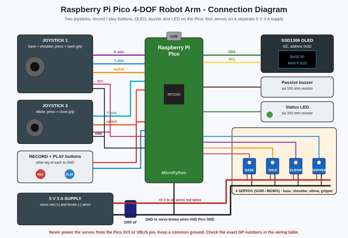
Connection diagram of the Raspberry Pi Pico 4-DOF robot arm with two joysticks, record and play buttons, SSD1306 OLED, buzzer, status LED and four servos on a separate 5 V 3 A supply

Build a Raspberry Pi Pico 4-DOF robot arm in MicroPython: steer the base, shoulder, elbow and gripper servos with two joysticks, record up to 20 poses to flash, and play them back in a smooth loop while an OLED shows every angle.

  • DifficultyAdvanced
  • Build time5–8 hours
  • Board / MCURaspberry Pi Pico
  • Parts12 items
  • CodeMicroPython

Need it ready-made? Buy Ready Project

A small desktop robot arm is one of the most satisfying builds in electronics: you move two joysticks and the arm turns, reaches and picks things up. This Raspberry Pi Pico robot arm goes one step further. Press Record at each position you like, press Play, and the arm repeats the whole sequence by itself in a smooth, endless loop – a simple pick-and-place “teach and repeat” robot like the ones used in factories, only on your desk.

Four micro servos move the base, shoulder, elbow and gripper. The Pico reads the joysticks, limits every joint to a safe range, eases the servos so they never jump, saves the recorded poses to a file in its flash memory, and shows all four angles on an SSD1306 OLED. The servos run from their own 5 V 3 A supply, which is the single most important detail for a reliable arm.

Connection diagram of the Raspberry Pi Pico 4-DOF robot arm with two joysticks, record and play buttons, SSD1306 OLED, buzzer, status LED and four servos on a separate 5 V 3 A supply

How It Works

  • Servo control: a hobby servo expects a pulse every 20 ms (50 Hz). A 0.5 ms pulse means 0°, 1.5 ms means 90° and 2.5 ms means 180°. The Pico has hardware PWM on every GPIO, so PWM.duty_ns() on GP16–GP19 sets each servo angle exactly without any extra driver board. The 3.3 V signal level is enough for SG90 and MG90S servos.
  • Three ADC pins, four joints: the Pico exposes only three analog inputs (GP26, GP27, GP28). Joystick 1 uses both axes – left/right turns the base, up/down moves the shoulder. Joystick 2 uses its up/down axis for the elbow. The gripper does not need analog control, so it uses the two joystick push switches: press joystick 1 to open the gripper a little at a time, press joystick 2 to close it. This keeps every input on a real, correctly wired pin with no multiplexer.
  • Smooth motion: the joysticks never set an angle directly. Each 20 ms loop, the stick position adds a small amount to a target angle (more deflection = faster), and the real servo angle is allowed to move at most 1.2° toward the target. A dead zone around the stick centre stops drift, and the centre value of each stick is measured at start-up.
  • Record: a short press on Record stores the four current angles as one pose (up to 20). The list is written to poses.json on the Pico’s flash straight away, so it survives power-off. Holding Record for 2 seconds clears all poses.
  • Playback: Play starts a loop through all poses. Between two poses all four joints move together over 1.2 seconds with “smoothstep” easing (slow start, fast middle, slow stop), then the arm holds for 0.4 seconds. Press Play again to stop and take back joystick control from the current position.
  • Feedback: the OLED shows every joint angle with a small bar, the mode (MAN or PLAY) and how many poses are stored. The buzzer beeps on each saved pose and on errors, and the status LED toggles at each playback step.

Components Required

  • Raspberry Pi Pico (or Pico W / Pico 2) with headers – 1
  • SG90 or MG90S micro servo (MG90S metal gear is better for shoulder and elbow) – 4
  • 4-DOF acrylic or 3D-printed mini robot arm kit (sized for SG90/MG90S) – 1
  • Dual-axis analog joystick module (KY-023 / PS2 type, with push switch) – 2
  • 12 mm tactile push buttons (Record and Play) – 2
  • 0.96 inch SSD1306 I2C OLED display, 128×64 – 1
  • Passive buzzer with 100 Ω series resistor – 1
  • 5 mm LED with 330 Ω resistor (status) – 1
  • 5 V 3 A DC adapter with DC jack breakout – 1
  • 1000 µF 10 V (or higher) electrolytic capacitor – 1
  • 1N5819 Schottky diode (only if the Pico runs from the 5 V supply) – 1
  • Breadboard or perfboard, servo extension leads and jumper wires – 1 set

Wiring Table

Module pinPico pinNotes
Base servo signal (orange)GP16 (pin 21)PWM slice 0A, 50 Hz
Shoulder servo signalGP17 (pin 22)PWM slice 0B
Elbow servo signalGP18 (pin 24)PWM slice 1A
Gripper servo signalGP19 (pin 25)PWM slice 1B
All servo red (+) wires5 V 3 A supply +Never from the Pico 3V3 or VBUS pin
All servo brown (–) wires5 V supply – and Pico GNDCommon ground is required for the signal to work
1000 µF capacitorAcross servo 5 V and GNDLong leg (+) to 5 V; absorbs current spikes
Joystick 1 VRxGP26 / ADC0 (pin 31)Base left / right
Joystick 1 VRyGP27 / ADC1 (pin 32)Shoulder up / down
Joystick 1 SWGP14 (pin 19)Gripper open (internal pull-up)
Joystick 2 VRyGP28 / ADC2 (pin 34)Elbow up / down
Joystick 2 VRxNot connectedFree axis (no fourth ADC pin)
Joystick 2 SWGP15 (pin 20)Gripper close (internal pull-up)
Both joysticks +5V / VCC3V3 OUT (pin 36)Power the pots from 3.3 V so the ADC never sees more than 3.3 V
Both joysticks GNDGND (pin 38)
Record buttonGP10 (pin 14) and GNDPressed = LOW
Play buttonGP11 (pin 15) and GNDPressed = LOW
Status LED anodeGP12 (pin 16) via 330 ΩCathode to GND
Passive buzzer +GP13 (pin 17) via 100 ΩBuzzer – to GND
OLED VCC / GND3V3 OUT (pin 36) / GNDCheck the pin order printed on your module
OLED SDA / SCLGP4 (pin 6) / GP5 (pin 7)I2C0, address 0x3C
5 V supply + (optional)VSYS (pin 39) via 1N5819Lets the Pico run without USB; the diode protects the PC if USB is plugged in too

Connection Diagram

The illustration near the top of this post shows how the boards, joysticks, servos and the separate power supply fit together. The drawing below lists every Pico pin with its physical pin number, and matches the wiring table and the code exactly.

Raspberry Pi Pico Robot Arm – Pin-Accurate Wiring Raspberry Pi Pico GP4 (pin 6) OLED SDA GP5 (pin 7) OLED SCL GP10 (pin 14) RECORD button, other leg to GND GP11 (pin 15) PLAY button, other leg to GND GP12 (pin 16) Status LED + 330 ohm to GND GP13 (pin 17) Passive buzzer + via 100 ohm, – to GND GP14 (pin 19) Joystick 1 SW (gripper open) GP15 (pin 20) Joystick 2 SW (gripper close) GP16-GP19 (21,22,24,25) Servo signals: base, shoulder, elbow, gripper GP26 ADC0 (pin 31) Joystick 1 VRx (base) GP27 ADC1 (pin 32) Joystick 1 VRy (shoulder) GP28 ADC2 (pin 34) Joystick 2 VRy (elbow); VRx not used 3V3 OUT (pin 36) Both joystick +5V/VCC pins and OLED VCC GND (pin 38) All module GNDs + 5 V supply minus (common ground) VSYS (pin 39) Optional: 5 V supply + through 1N5819 diode Servo red wires go to the 5 V 3 A supply +, brown wires to its minus, with a 1000 uF capacitor across the rail.
Pin-accurate connection diagram for the Raspberry Pi Pico 4-DOF robot arm.

Power Supply Notes

  • Each SG90 can draw 500–700 mA when it starts moving or stalls, and an MG90S even more. Four of them easily need 2–3 A in short bursts, which is why a 5 V 3 A adapter is used. Powering servos from the Pico or a USB port causes brown-outs, random resets and jittering.
  • Join the supply minus to the Pico GND. Without this common ground the servos cannot “see” the signal pulses.
  • Place the 1000 µF capacitor close to the servo power rail. Use short, thick wires (22 AWG or thicker) for the servo 5 V and GND.
  • While programming, the Pico can stay on USB with the servos on the adapter. For stand-alone use, feed the 5 V supply into VSYS through the 1N5819 diode.

Code

Flash the latest MicroPython UF2 for your board (hold BOOTSEL while plugging in the Pico and drop the file on the RPI-RP2 drive). In Thonny, open Tools → Manage packages, search for ssd1306 and install it (or copy the ssd1306.py driver from the micropython-lib repository to the Pico). Then save the code below to the Pico as main.py so the arm starts automatically on power-up. The project needs no Wi-Fi, so it also runs on a plain Pico. The code was syntax-checked and the record/playback logic was tested in a simulation before publishing.

# Raspberry Pi Pico 4-DOF Robot Arm - Joysticks, Record & Playback, OLED
# Base, shoulder, elbow and gripper servos (SG90 / MG90S) on a separate 5 V 3 A supply
# Arduino Project Hub - ardiunoprojecthub.online
# Needs ssd1306.py on the Pico (Thonny: Tools > Manage packages > "ssd1306")
# Save this file to the Pico as main.py

from machine import Pin, PWM, ADC, I2C
import time, json
import ssd1306

# ---------- pin map (matches the wiring table) ----------
SERVO_PINS = (16, 17, 18, 19)          # base, shoulder, elbow, gripper signal wires
NAMES = ("BASE", "SHLD", "ELBW", "GRIP")
# per-joint limits in degrees: (min, max, home). Tune these for your arm!
LIMITS = ((0, 180, 90),     # base
          (15, 165, 90),    # shoulder
          (20, 160, 90),    # elbow
          (30, 110, 70))    # gripper: 30 = open, 110 = closed (check yours)

JOY_BASE = ADC(26)        # ADC0 <- joystick 1 VRx  (turn left / right)
JOY_SHLD = ADC(27)        # ADC1 <- joystick 1 VRy  (shoulder up / down)
JOY_ELBW = ADC(28)        # ADC2 <- joystick 2 VRy  (elbow up / down)
# The Pico has only three free ADC pins, so the gripper uses the two
# joystick push switches: joystick 1 SW = open, joystick 2 SW = close.
SW_OPEN = Pin(14, Pin.IN, Pin.PULL_UP)
SW_CLOSE = Pin(15, Pin.IN, Pin.PULL_UP)
BTN_REC = Pin(10, Pin.IN, Pin.PULL_UP)     # short press = store pose, hold 2 s = clear all
BTN_PLAY = Pin(11, Pin.IN, Pin.PULL_UP)    # start / stop playback loop
LED = Pin(12, Pin.OUT, value=0)            # status LED (330 ohm to GND)
buzzer = PWM(Pin(13))                      # passive buzzer through 100 ohm
buzzer.duty_u16(0)

i2c = I2C(0, sda=Pin(4), scl=Pin(5), freq=400000)
oled = ssd1306.SSD1306_I2C(128, 64, i2c)

# ---------- settings ----------
PULSE_MIN_NS = 500_000     # pulse width for 0 degrees (0.5 ms)
PULSE_MAX_NS = 2_500_000   # pulse width for 180 degrees (2.5 ms)
DEADZONE = 4000            # ignore small stick movement around the centre (of 65535)
JOG_SPEED = 2.0            # max degrees per 20 ms loop at full stick deflection
GRIP_SPEED = 1.5           # degrees per loop while a gripper switch is held
SMOOTH_STEP = 1.2          # max degrees each servo may move per loop (smooth motion)
MAX_POSES = 20             # how many poses can be recorded
PLAY_MOVE_MS = 1200        # travel time between two poses during playback
PLAY_HOLD_MS = 400         # pause at each pose
POSE_FILE = "poses.json"
LOOP_MS = 20

# ---------- servos ----------
servos = []
for pin in SERVO_PINS:
    s = PWM(Pin(pin))
    s.freq(50)             # standard 50 Hz hobby servo signal (20 ms frame)
    servos.append(s)


def write_servo(i, angle):
    lo, hi, _ = LIMITS[i]
    angle = max(lo, min(hi, angle))
    ns = PULSE_MIN_NS + int((PULSE_MAX_NS - PULSE_MIN_NS) * angle / 180)
    servos[i].duty_ns(ns)


current = [float(l[2]) for l in LIMITS]   # where each servo is now
target = list(current)                     # where each servo should go
for i in range(4):
    write_servo(i, current[i])


def smooth_update():
    """Move every servo a small step toward its target (no sudden jumps)."""
    for i in range(4):
        d = target[i] - current[i]
        if d > SMOOTH_STEP:
            d = SMOOTH_STEP
        elif d < -SMOOTH_STEP:
            d = -SMOOTH_STEP
        current[i] += d
        write_servo(i, current[i])


# ---------- helpers ----------
def beep(freq=1500, ms=60):
    buzzer.freq(freq)
    buzzer.duty_u16(20000)
    time.sleep_ms(ms)
    buzzer.duty_u16(0)


def clamp_target(i):
    lo, hi, _ = LIMITS[i]
    target[i] = max(lo, min(hi, target[i]))


def stick(adc, centre):
    """Return -1.0 ... +1.0 from a joystick axis, 0 inside the dead zone."""
    v = adc.read_u16() - centre
    if -DEADZONE < v < DEADZONE:
        return 0.0
    if v > 0:
        return (v - DEADZONE) / (65535 - centre - DEADZONE)
    return (v + DEADZONE) / (centre - DEADZONE)


def calibrate_centre(adc):
    """Average 32 readings at start-up (do not touch the sticks)."""
    total = 0
    for _ in range(32):
        total += adc.read_u16()
        time.sleep_ms(2)
    return total // 32


def load_poses():
    try:
        with open(POSE_FILE) as f:
            data = json.load(f)
        return [[float(a) for a in pose[:4]] for pose in data][:MAX_POSES]
    except (OSError, ValueError, TypeError):
        return []             # first run: no file yet


def save_poses(poses):
    with open(POSE_FILE, "w") as f:
        json.dump([[round(a, 1) for a in pose] for pose in poses], f)


def show(mode, poses, msg=""):
    oled.fill(0)
    oled.text("PICO ROBOT ARM", 8, 0)
    oled.hline(0, 10, 128, 1)
    for i in range(4):
        y = 14 + i * 9
        oled.text(NAMES[i], 0, y)
        oled.text("{:3d}".format(int(current[i])), 40, y)
        bar = int(current[i] * 52 / 180)           # small angle bar
        oled.rect(70, y + 1, 54, 6, 1)
        oled.fill_rect(71, y + 2, bar, 4, 1)
    oled.text("{} P:{}/{}".format(mode, len(poses), MAX_POSES), 0, 50)
    if msg:
        oled.fill_rect(0, 56, 128, 8, 0)
        oled.text(msg[:16], 0, 56)
    oled.show()


class Button:
    """Debounced button with short-press and long-press detection."""
    def __init__(self, pin, long_ms=2000):
        self.pin = pin
        self.long_ms = long_ms
        self.down_at = None
        self.long_done = False

    def poll(self):
        """Returns 'short', 'long' or None."""
        pressed = self.pin.value() == 0
        now = time.ticks_ms()
        if pressed and self.down_at is None:
            self.down_at = now
            self.long_done = False
        elif pressed and not self.long_done and time.ticks_diff(now, self.down_at) >= self.long_ms:
            self.long_done = True
            return "long"
        elif not pressed and self.down_at is not None:
            held = time.ticks_diff(now, self.down_at)
            self.down_at = None
            if not self.long_done and held >= 40:      # 40 ms debounce
                return "short"
        return None


# ---------- start-up ----------
show("START", [], "centre sticks...")
c_base = calibrate_centre(JOY_BASE)
c_shld = calibrate_centre(JOY_SHLD)
c_elbw = calibrate_centre(JOY_ELBW)
poses = load_poses()
rec_btn = Button(BTN_REC)
play_btn = Button(BTN_PLAY)
mode = "MAN"            # MAN = joystick control, PLAY = playback loop
play_index = 0
seg_start = 0
seg_from = list(current)
holding = False
msg = "loaded {} poses".format(len(poses)) if poses else "ready"
beep(1200, 80)
beep(1800, 80)
last_screen = 0

while True:
    t0 = time.ticks_ms()
    r = rec_btn.poll()
    pl = play_btn.poll()

    # ----- play button: start / stop playback -----
    if pl == "short":
        if mode == "MAN":
            if len(poses) >= 1:
                mode = "PLAY"
                play_index = 0
                seg_from = list(current)
                seg_start = t0
                holding = False
                LED.value(1)
                msg = "playing"
                beep(2000, 60)
            else:
                msg = "no poses!"
                beep(400, 200)
        else:
            mode = "MAN"
            target[:] = current         # stop where the arm is now
            LED.value(0)
            msg = "stopped"
            beep(800, 60)

    # ----- record button -----
    if r == "short" and mode == "MAN":
        if len(poses) < MAX_POSES:
            poses.append([round(a, 1) for a in current])
            save_poses(poses)
            msg = "pose {} saved".format(len(poses))
            LED.value(1)
            beep(1500, 50)
            LED.value(0)
        else:
            msg = "memory full"
            beep(400, 200)
    elif r == "long" and mode == "MAN":
        poses = []
        save_poses(poses)
        msg = "all cleared"
        beep(600, 300)

    if mode == "MAN":
        # joystick jog: the further the stick, the faster the joint moves
        target[0] += stick(JOY_BASE, c_base) * JOG_SPEED
        target[1] += stick(JOY_SHLD, c_shld) * JOG_SPEED
        target[2] += stick(JOY_ELBW, c_elbw) * JOG_SPEED
        if SW_OPEN.value() == 0:
            target[3] -= GRIP_SPEED
        if SW_CLOSE.value() == 0:
            target[3] += GRIP_SPEED
        for i in range(4):
            clamp_target(i)
        smooth_update()
    else:
        # playback: ease from the previous pose to the next one, then hold
        goal = poses[play_index]
        el = time.ticks_diff(t0, seg_start)
        if not holding:
            k = min(1.0, el / PLAY_MOVE_MS)
            k = k * k * (3 - 2 * k)             # smoothstep easing: slow-fast-slow
            for i in range(4):
                current[i] = seg_from[i] + (goal[i] - seg_from[i]) * k
                write_servo(i, current[i])
            if el >= PLAY_MOVE_MS:
                holding = True
                seg_start = t0
        elif el >= PLAY_HOLD_MS:
            holding = False
            seg_from = list(goal)
            seg_start = t0
            play_index = (play_index + 1) % len(poses)     # loop forever
            LED.toggle()
        target[:] = current
        msg = "pose {}/{}".format(play_index + 1, len(poses))

    if time.ticks_diff(t0, last_screen) > 150:     # refresh OLED ~6 times a second
        show(mode, poses, msg)
        last_screen = t0

    wait = LOOP_MS - time.ticks_diff(time.ticks_ms(), t0)
    if wait > 0:
        time.sleep_ms(wait)

Calibration and Testing

  • Before fitting the horns: power everything once without the servo horns attached. At start-up every servo goes to its home angle (90°, gripper 70°). Now fit the horns so the arm stands straight up and the gripper is half open.
  • Keep the sticks still at power-up: the first half second measures the joystick centre. If a joint creeps on its own, restart without touching the sticks, or raise DEADZONE.
  • Set safe limits: move each joint slowly to its mechanical end with the joystick and read the angle on the OLED. Enter values a few degrees inside these ends in LIMITS. This stops servos from pushing against the frame, which overheats them.
  • Gripper: find the angle where the jaws just close on an object and use it as the maximum for the gripper, so it grips without stalling. If open/close are reversed on your kit, swap the -= and += lines for SW_OPEN and SW_CLOSE.
  • Direction: if a stick moves a joint the opposite way you expect, put a minus sign in front of that stick(...) call.
  • Teach a sequence: move to a pose, press Record (short beep), repeat for every step, then press Play. Change PLAY_MOVE_MS and PLAY_HOLD_MS for faster or slower playback.

Troubleshooting

ProblemFix
Pico resets or the OLED goes blank when the arm movesThe servos are pulling the supply down. Use a separate 5 V 3 A supply, add the 1000 µF capacitor and make sure the servos are not powered from the Pico.
Servos jitter or do not move at allThe grounds are not joined. Connect the 5 V supply minus to a Pico GND pin. Also check each signal wire is on GP16–GP19 in the right order.
A joint moves on its ownJoystick drift. Restart with the sticks centred so the centre is measured again, or raise DEADZONE to 6000.
One joystick axis does nothingCheck VRx/VRy go to GP26, GP27 and GP28 and that the joystick VCC pin is on 3V3 OUT, not on VBUS. Joystick 2’s VRx is unused on purpose.
ImportError: no module named ‘ssd1306’The OLED driver is not on the Pico. Install the ssd1306 package in Thonny or copy ssd1306.py to the Pico’s root folder.
OSError: [Errno 5] EIO at start-upThe OLED is not found on I2C. Check SDA on GP4, SCL on GP5 and the module address (0x3C is used).
Servo buzzes and gets hot at one endIt is pressing against a mechanical stop. Reduce the max or raise the min angle for that joint in LIMITS.
Poses are lost after unpluggingThe code must run from the Pico’s flash as main.py; check that poses.json appears on the Pico in Thonny’s file panel.
“no poses!” when pressing PlayRecord at least one pose first. Two or more poses are needed to see the arm move between them.

Ideas to Extend

  • Add a PCA9685 16-channel servo board on I2C to build a 6-DOF arm with wrist rotation.
  • Use a CD4051 analog multiplexer on one ADC pin to read both axes of both joysticks plus extra potentiometers.
  • Use a Pico W to store several named sequences and start them from a phone web page.
  • Add an HC-SR04 sensor so the arm starts its pick-and-place loop only when an object is placed in front of it.

ESP32 Smart Curtain Opener with Stepper, LDR, OLED & Web Control

Connection diagram of the ESP32 smart curtain opener with 28BYJ-48 stepper on a ULN2003 driver, limit switch, push button, LDR sensor and SSD1306 OLED

Build an ESP32 smart curtain opener that pulls the curtain cord with a 28BYJ-48 stepper, opens with daylight or at a set time, and is controlled from a phone web page, a push button and an OLED status screen.

  • DifficultyIntermediate
  • Build time2–4 hours
  • Board / MCUESP32 DevKit V1
  • Parts9 items
  • CodeArduino C++

Need it ready-made? Buy Ready Project

Opening the curtains every morning and closing them every evening is a small job that is easy to forget. This ESP32 smart curtain opener does it for you. A 28BYJ-48 stepper motor pulls the curtain cord loop, a limit switch tells the ESP32 where “fully closed” is, and an LDR watches the daylight. You can open or close the curtain from a phone web page, set it to any position with a slider, give it daily open and close times, or let it follow the sun. A push button on the box and a small OLED screen work even when Wi-Fi is down.

The project needs no cloud service and no app: the ESP32 hosts its own page at http://curtain.local and gets the time from an NTP server. It suits light curtains on a cord or rail loop; for heavy curtains, see the ideas section for a stronger motor.

Connection diagram of the ESP32 smart curtain opener with 28BYJ-48 stepper on a ULN2003 driver, limit switch, push button, LDR sensor and SSD1306 OLED

How It Works

  • Stepper drive: the 28BYJ-48 is a geared stepper with about 4096 half-steps per output turn, so it is slow but strong and very precise. The ESP32 drives its four coils through the ULN2003 transistor array using an 8-step half-step pattern. Stepping is non-blocking: runMotor() makes one half-step only when 1.2 ms has passed, so the web page, button and screen stay responsive while the curtain moves. The coils are switched off when the motor stops, so the motor stays cool.
  • Position and homing: position 0 is “fully closed” and TRAVEL_DEFAULT half-steps is “fully open” (20480 = 5 output turns by default). At power-up the ESP32 turns the motor toward the closed end until the limit switch is pressed, then sets the position to 0. The switch is also checked during every closing move, so the motor can never wind past the end.
  • Light mode: the LDR and 10 kΩ resistor form a voltage divider on GPIO34 (an ADC1 pin that works together with Wi-Fi). More light gives a higher reading (0–4095). When the reading stays above the “bright” level for 60 seconds the curtain opens; when it stays below the “dark” level for 60 seconds it closes. The 60-second wait stops passing clouds or car headlights from moving the curtain.
  • Daily timers: after joining Wi-Fi the ESP32 sets its clock from pool.ntp.org with the Indian time zone (IST-5:30). Once a minute it compares the time with the open and close times you saved on the web page. Settings are kept in flash with the Preferences library, so they survive a power cut.
  • Controls and display: a short press of the button opens a closed curtain, closes an open one, or stops it while it is moving. The OLED shows the state (OPENING, CLOSING, OPEN, CLOSED), the percent open with a bar, the light reading, the time and the IP address. The web page polls /data every second for a small JSON reply.

Components Required

  • ESP32 DevKit V1 (30-pin) board – 1
  • 28BYJ-48 5 V stepper motor with ULN2003 driver board – 1
  • 0.96 inch SSD1306 I2C OLED display, 128×64 – 1
  • Micro limit switch (roller lever, normally open) – 1
  • 6 mm tactile push button – 1
  • LDR (photoresistor, 5 mm) and 10 kΩ resistor – 1 each
  • 5 V 2 A DC adapter with DC jack breakout – 1
  • GT2 pulley or 3D-printed cord spool, curtain cord loop and small mounting bracket – 1 set
  • Breadboard or perfboard and jumper wires – 1 set

Wiring Table

Module pinESP32 pinNotes
ULN2003 IN1GPIO26Coil A
ULN2003 IN2GPIO25Coil B
ULN2003 IN3GPIO33Coil C
ULN2003 IN4GPIO32Coil D
ULN2003 + (5–12 V)VIN / adapter +5 VRemove the ULN2003 power jumper only if you add a separate motor switch
ULN2003 – (GND)GNDMust share ground with the ESP32
28BYJ-48 5-pin plugULN2003 motor socketThe plug is keyed; push it fully in
5 V adapter +VINPowers the ESP32 through its regulator; do not plug in USB and the adapter if your board lacks a VIN diode
5 V adapter –GNDCommon ground
OLED VCC / GND3V3 / GNDCheck the pin order printed on your module
OLED SDA / SCLGPIO21 / GPIO22Default ESP32 I2C pins, address 0x3C
LDR leg 13V3Polarity does not matter
LDR leg 2GPIO34Also connect the 10 kΩ resistor from GPIO34 to GND
Limit switch COMGPIO13Internal pull-up enabled in the code
Limit switch NOGNDMount it so the curtain (or a stop on the cord) presses it when fully closed
Push buttonGPIO27 and GNDPressed = LOW

Connection Diagram

The diagram near the top of this post shows the full layout with the power supply. The drawing below lists every ESP32 pin and what it connects to, and matches the wiring table and the code.

ESP32 Smart Curtain Opener – Pin-Accurate Wiring ESP32 DevKit V1 GPIO26 ULN2003 IN1 GPIO25 ULN2003 IN2 GPIO33 ULN2003 IN3 GPIO32 ULN2003 IN4 (motor plugs into the 5-pin socket) VIN (5 V) 5 V adapter + and ULN2003 +5V GND Adapter -, ULN2003 GND, OLED GND, switch, button, 10k 3V3 OLED VCC and one leg of the LDR GPIO21 (SDA) OLED SDA GPIO22 (SCL) OLED SCL GPIO34 (ADC) LDR other leg + 10k resistor to GND GPIO13 Limit switch COM; NO contact to GND GPIO27 Push button; other leg to GND Stepper current comes from the 5 V adapter, never from the 3V3 pin. All grounds are joined.
Pin-accurate connection diagram for the ESP32 smart curtain opener.

Mechanical Setup

  • Most window curtains on a rail have a cord loop. Fit a pulley or a printed spool with a groove on the motor shaft and wrap the cord once around it, so turning the motor one way opens the curtain and the other way closes it.
  • Fix the motor to the wall or window frame with a small bracket and pull the cord tight with a tension pulley at the bottom, so it cannot slip.
  • Mount the limit switch where the curtain edge or a bead clamped on the cord presses it at the fully closed position.
  • If the curtain moves the wrong way, swap the IN1/IN4 and IN2/IN3 wires, or simply rotate the motor mounting so the cord wraps the other way.

Code

Install the ESP32 boards package (by Espressif) in the Arduino IDE, select ESP32 Dev Module, and install Adafruit SSD1306 and Adafruit GFX from the Library Manager. WiFi, WebServer, ESPmDNS and Preferences come with the ESP32 core. Replace YOUR_WIFI_SSID and YOUR_WIFI_PASSWORD with your own network details. The sketch was compile-checked for the ESP32 Dev Module (about 79% of the default app partition).

/*
  ESP32 Smart Curtain Opener
  28BYJ-48 stepper + ULN2003, home limit switch, LDR auto mode,
  daily open/close times (NTP), SSD1306 OLED and a Wi-Fi web page.
  Project #73 - ardiunoprojecthub.online

  Pins (ESP32 DevKit V1):
    ULN2003 IN1..IN4 -> GPIO26, GPIO25, GPIO33, GPIO32
    Limit switch (curtain fully CLOSED) -> GPIO13 to GND (INPUT_PULLUP)
    Push button (open / stop / close)   -> GPIO27 to GND (INPUT_PULLUP)
    LDR divider (LDR to 3V3, 10k to GND) -> GPIO34 (ADC1)
    OLED SDA -> GPIO21, OLED SCL -> GPIO22
*/
#include <WiFi.h>
#include <WebServer.h>
#include <ESPmDNS.h>
#include <Preferences.h>
#include <Wire.h>
#include <Adafruit_GFX.h>
#include <Adafruit_SSD1306.h>
#include <time.h>

// ---------- user settings ----------
const char* WIFI_SSID = "YOUR_WIFI_SSID";       // put your Wi-Fi name here
const char* WIFI_PASS = "YOUR_WIFI_PASSWORD";   // put your Wi-Fi password here
const char* TZ_INFO   = "IST-5:30";             // POSIX time zone (India)
const long  TRAVEL_DEFAULT = 20480;             // half-steps from closed to open (5 turns)
const uint16_t STEP_US = 1200;                  // time per half-step (lower = faster)

// ---------- pins ----------
const uint8_t COIL[4] = {26, 25, 33, 32};
const uint8_t PIN_LIMIT  = 13;
const uint8_t PIN_BUTTON = 27;
const uint8_t PIN_LDR    = 34;

Adafruit_SSD1306 oled(128, 64, &Wire, -1);
WebServer server(80);
Preferences prefs;

// half-step sequence for the 28BYJ-48 (IN1..IN4)
const uint8_t SEQ[8][4] = {
  {1,0,0,0},{1,1,0,0},{0,1,0,0},{0,1,1,0},
  {0,0,1,0},{0,0,1,1},{0,0,0,1},{1,0,0,1}
};

long position = 0;        // 0 = closed, travel = fully open
long target = 0;
long travel = TRAVEL_DEFAULT;
bool homed = false;
int  seqIndex = 0;
unsigned long lastStepUs = 0;
int  lastDir = 1;         // direction of the last move (for the button)

bool autoLight = false;   // LDR auto mode
int  ldrOpen = 2600;      // ADC above this = bright -> open
int  ldrClose = 900;      // ADC below this = dark -> close
int  openMin = 7 * 60;    // schedule open time (minutes after midnight), -1 = off
int  closeMin = 19 * 60;  // schedule close time, -1 = off
int  lastSchedMin = -1;
int  ldrValue = 0;
unsigned long brightSince = 0, darkSince = 0;

// ---------- motor ----------
void coilsOff() { for (int i = 0; i < 4; i++) digitalWrite(COIL[i], LOW); }

void stepOnce(int dir) {
  seqIndex = (seqIndex + dir + 8) % 8;
  for (int i = 0; i < 4; i++) digitalWrite(COIL[i], SEQ[seqIndex][i]);
  position += dir;
}

int percentOpen() { return (int)constrain(position * 100L / travel, 0L, 100L); }

void moveToPercent(int pct) {
  pct = constrain(pct, 0, 100);
  target = travel * pct / 100;
  if (target != position) lastDir = (target > position) ? 1 : -1;
}

void stopMotor() { target = position; coilsOff(); prefs.putLong("pos", position); }

// called every loop: makes at most one half-step, never blocks
void runMotor() {
  if (position == target) return;
  if (micros() - lastStepUs < STEP_US) return;
  lastStepUs = micros();
  int dir = (target > position) ? 1 : -1;
  if (dir < 0 && digitalRead(PIN_LIMIT) == LOW) {   // reached the closed end
    position = 0; target = 0; coilsOff(); prefs.putLong("pos", 0);
    return;
  }
  stepOnce(dir);
  if (position == target) { coilsOff(); prefs.putLong("pos", position); }
}

// drive toward the limit switch at boot so position 0 is exact
void homeCurtain() {
  oled.clearDisplay(); oled.setCursor(0, 0); oled.println("Homing..."); oled.display();
  long maxSteps = travel + 4096;
  while (digitalRead(PIN_LIMIT) == HIGH && maxSteps-- > 0) {
    stepOnce(-1);
    delayMicroseconds(STEP_US);
    if ((maxSteps & 255) == 0) yield();
  }
  coilsOff();
  homed = (digitalRead(PIN_LIMIT) == LOW);
  position = 0; target = 0;
  Serial.println(homed ? "Homed at limit switch" : "Limit switch not found!");
}

// ---------- button: short press = open / close / stop ----------
void checkButton() {
  static bool last = HIGH;
  static unsigned long tDown = 0;
  bool now = digitalRead(PIN_BUTTON);
  if (now != last) {
    if (now == LOW) tDown = millis();
    else if (millis() - tDown > 40) {               // released after a clean press
      if (position != target) stopMotor();          // moving -> stop
      else if (percentOpen() >= 50) moveToPercent(0);
      else moveToPercent(100);
    }
    last = now;
  }
}

// ---------- automatic modes ----------
void checkAuto() {
  static unsigned long lastRead = 0;
  if (millis() - lastRead < 1000) return;
  lastRead = millis();
  ldrValue = analogRead(PIN_LDR);

  // daily schedule from NTP time
  struct tm t;
  if (getLocalTime(&t, 10)) {
    int m = t.tm_hour * 60 + t.tm_min;
    if (m != lastSchedMin) {
      if (m == openMin)  moveToPercent(100);
      if (m == closeMin) moveToPercent(0);
      lastSchedMin = m;
    }
  }

  // light mode: needs 60 s of steady light/dark to avoid clouds or headlights
  if (!autoLight) { brightSince = darkSince = 0; return; }
  if (ldrValue > ldrOpen) { if (!brightSince) brightSince = millis(); } else brightSince = 0;
  if (ldrValue < ldrClose) { if (!darkSince) darkSince = millis(); } else darkSince = 0;
  if (brightSince && millis() - brightSince > 60000 && percentOpen() < 100 && position == target) moveToPercent(100);
  if (darkSince && millis() - darkSince > 60000 && percentOpen() > 0 && position == target) moveToPercent(0);
}

// ---------- OLED ----------
void drawOled() {
  static unsigned long last = 0;
  // refresh slower while the motor runs so the I2C transfer does not slow the stepping
  if (millis() - last < (position == target ? 300UL : 1000UL)) return;
  last = millis();
  oled.clearDisplay();
  oled.setTextSize(1); oled.setCursor(0, 0);
  oled.print("Curtain ");
  oled.print(position == target ? (percentOpen() == 0 ? "CLOSED" : (percentOpen() == 100 ? "OPEN" : "STOP")) : (target > position ? "OPENING" : "CLOSING"));
  oled.setTextSize(2); oled.setCursor(0, 14); oled.print(percentOpen()); oled.print("%");
  oled.drawRect(60, 16, 66, 12, SSD1306_WHITE);
  oled.fillRect(62, 18, percentOpen() * 62 / 100, 8, SSD1306_WHITE);
  oled.setTextSize(1); oled.setCursor(0, 36);
  oled.print("Light "); oled.print(ldrValue); oled.print(autoLight ? " AUTO" : " man");
  oled.setCursor(0, 46);
  struct tm t;
  if (getLocalTime(&t, 5)) { char b[6]; strftime(b, 6, "%H:%M", &t); oled.print(b); }
  if (!homed) oled.print(" NO HOME!");
  oled.setCursor(0, 56);
  oled.print(WiFi.status() == WL_CONNECTED ? WiFi.localIP().toString() : String("Wi-Fi offline"));
  oled.display();
}

// ---------- web page ----------
String hhmm(int m) { if (m < 0) return ""; char b[6]; sprintf(b, "%02d:%02d", m / 60, m % 60); return b; }
int parseHHMM(const String& s) {
  if (s.length() < 4) return -1;
  int c = s.indexOf(':'); if (c < 0) return -1;
  return constrain(s.substring(0, c).toInt(), 0, 23) * 60 + constrain(s.substring(c + 1).toInt(), 0, 59);
}

const char PAGE[] PROGMEM = R"HTML(<!doctype html><html><head><meta name=viewport content="width=device-width,initial-scale=1">
<title>Smart Curtain</title><style>body{font-family:Arial;max-width:420px;margin:auto;padding:12px;background:#f3f6fb}
.c{background:#fff;border-radius:12px;padding:14px;margin:10px 0;box-shadow:0 1px 4px #0002}button{font-size:18px;padding:10px 16px;margin:4px;border:0;border-radius:8px;background:#1565c0;color:#fff}
#p{font-size:42px;font-weight:bold}input[type=range]{width:100%}</style></head><body>
<h2>ESP32 Smart Curtain</h2><div class=c><div id=p>--%</div><div id=s></div>
<button onclick="go('/move?pct=100')">Open</button><button onclick="go('/stop')">Stop</button><button onclick="go('/move?pct=0')">Close</button>
<p>Set position: <input type=range id=r min=0 max=100 onchange="go('/move?pct='+this.value)"></p></div>
<div class=c><b>Automatic</b><p><label><input type=checkbox id=a onchange="go('/set?auto='+(this.checked?1:0))"> Open with daylight, close at dark</label></p>
<p>Light sensor: <span id=l></span></p>
<p>Open at <input type=time id=o> Close at <input type=time id=cl> <button onclick="go('/set?open='+o.value+'&close='+cl.value)">Save</button></p><small>Clear a time box to switch that timer off.</small></div>
<script>function go(u){fetch(u).then(upd)}
function upd(){fetch('/data').then(r=>r.json()).then(d=>{p.textContent=d.pct+'%';s.textContent=d.state+(d.homed?'':' (not homed!)');l.textContent=d.ldr;
a.checked=d.auto;if(document.activeElement!=r)r.value=d.pct;if(document.activeElement!=o)o.value=d.open;if(document.activeElement!=cl)cl.value=d.close;})}
setInterval(upd,1000);upd();</script></body></html>)HTML";

void handleData() {
  String st = position == target ? "Stopped" : (target > position ? "Opening" : "Closing");
  String j = "{\"pct\":" + String(percentOpen()) + ",\"state\":\"" + st + "\",\"ldr\":" + String(ldrValue) +
             ",\"auto\":" + (autoLight ? "true" : "false") + ",\"homed\":" + (homed ? "true" : "false") +
             ",\"open\":\"" + hhmm(openMin) + "\",\"close\":\"" + hhmm(closeMin) + "\"}";
  server.send(200, "application/json", j);
}

void setupWeb() {
  server.on("/", []() { server.send_P(200, "text/html", PAGE); });
  server.on("/data", handleData);
  server.on("/move", []() { moveToPercent(server.arg("pct").toInt()); server.send(200, "text/plain", "OK"); });
  server.on("/stop", []() { stopMotor(); server.send(200, "text/plain", "OK"); });
  server.on("/set", []() {
    if (server.hasArg("auto")) { autoLight = server.arg("auto") == "1"; prefs.putBool("auto", autoLight); }
    if (server.hasArg("open"))  { openMin = parseHHMM(server.arg("open"));   prefs.putInt("open", openMin); }
    if (server.hasArg("close")) { closeMin = parseHHMM(server.arg("close")); prefs.putInt("close", closeMin); }
    server.send(200, "text/plain", "OK");
  });
  server.begin();
}

void setup() {
  Serial.begin(115200);
  for (int i = 0; i < 4; i++) pinMode(COIL[i], OUTPUT);
  coilsOff();
  pinMode(PIN_LIMIT, INPUT_PULLUP);
  pinMode(PIN_BUTTON, INPUT_PULLUP);
  analogReadResolution(12);

  Wire.begin(21, 22);
  Wire.setClock(400000);                    // fast I2C = shorter OLED updates
  if (!oled.begin(SSD1306_SWITCHCAPVCC, 0x3C)) Serial.println("OLED not found");
  oled.setTextColor(SSD1306_WHITE);

  prefs.begin("curtain", false);
  travel   = prefs.getLong("travel", TRAVEL_DEFAULT);
  autoLight = prefs.getBool("auto", false);
  openMin  = prefs.getInt("open", openMin);
  closeMin = prefs.getInt("close", closeMin);

  homeCurtain();

  WiFi.mode(WIFI_STA);
  WiFi.begin(WIFI_SSID, WIFI_PASS);
  unsigned long t0 = millis();
  while (WiFi.status() != WL_CONNECTED && millis() - t0 < 15000) delay(250);
  if (WiFi.status() == WL_CONNECTED) {
    Serial.print("IP: "); Serial.println(WiFi.localIP());
    MDNS.begin("curtain");                    // http://curtain.local
    configTzTime(TZ_INFO, "pool.ntp.org", "time.google.com");
  } else Serial.println("Wi-Fi offline - button and light mode still work");
  setupWeb();
}

void loop() {
  runMotor();
  server.handleClient();
  checkButton();
  checkAuto();
  drawOled();
}

Calibration and Testing

  • Open the Serial Monitor at 115200 baud. At power-up the motor turns toward the closed side until the limit switch clicks, then prints Homed at limit switch and the IP address.
  • Open http://curtain.local (or the IP shown on the OLED) on a phone on the same Wi-Fi. Press Open and count how far the curtain travels. If it stops short or runs too far, change TRAVEL_DEFAULT (4096 half-steps = one output turn) and upload again.
  • Cover the LDR with your hand and watch the light value on the page. Note the reading in normal daylight and at dusk, then set ldrOpen and ldrClose between them.
  • Enter open and close times on the page and press Save. Clear a time box and save to switch that timer off.
  • If the motor misses steps or buzzes, raise STEP_US to 1500–2000 µs. Lower values move faster but give less torque.

Troubleshooting

ProblemFix
Motor hums but does not turnThe coil order is wrong or a wire is loose. Check IN1–IN4 go to GPIO26, 25, 33, 32 in that order, and that the 5-pin plug is fully seated. Increase STEP_US if the load is heavy.
ULN2003 LEDs blink but the ESP32 resetsThe supply is too weak. Use a 5 V 2 A adapter, keep the grounds joined, and add a 470 µF capacitor across the 5 V rail.
“Limit switch not found!” at bootHoming ran for a full travel without a switch press. Check the switch is wired COM to GPIO13 and NO to GND, and that the motor turns toward the closed side (swap the coil wires if not).
Curtain closes but never opensThe position is clamped at 0 when the switch is pressed. If the switch stays pressed, move it so the curtain releases it after a few millimetres.
Light mode never triggersThe LDR reading stays between the two levels. Read the value on the web page and adjust ldrOpen and ldrClose. Remember there is a 60-second delay on purpose.
Timers run at the wrong timeThe clock comes from NTP, so Wi-Fi is needed after each power-up. Change TZ_INFO if you are not in India (for example “GMT0” for UK winter time).
Web page does not openUse the IP address on the OLED instead of curtain.local (some Android phones do not support mDNS), and use a 2.4 GHz network.

Ideas to Extend

  • Swap the 28BYJ-48 for a NEMA 17 stepper and an A4988 driver (same STEP/DIR idea) for heavy blackout curtains.
  • Add a second limit switch at the open end so the travel length is measured automatically.
  • Add a DHT22 and close the curtain on hot afternoons to keep the room cool.

Wemos D1 Mini Wi-Fi Lux Meter with BH1750 & OLED

Connection diagram of the Wemos D1 Mini Wi-Fi lux meter with BH1750 light sensor and SSD1306 OLED on the I2C bus (D1 SCL, D2 SDA) and a hold button on D5

Build a pocket Wi-Fi lux meter with a Wemos D1 Mini, a BH1750 light sensor and a 0.96 inch OLED that shows light level, min/max and a room rating, plus a live phone web page.

  • DifficultyEasy
  • Build time1–2 hours
  • Board / MCUWemos D1 Mini (ESP8266)
  • Parts6 items
  • CodeArduino C++

Need it ready-made? Buy Ready Project

Is your study desk bright enough? Does the plant corner get enough light? Is the workshop bench lit well for soldering? Our eyes adapt so well that we are bad at judging light. This small Wemos D1 Mini lux meter measures light in lux with a BH1750 sensor, shows the reading on a 0.96 inch OLED with a simple rating (Dark, Dim, Living room, Reading, Office / desk, Bright, Direct sun) and keeps the minimum and maximum values. It also hosts a live web page, so you can place the sensor in one spot and read it on your phone from across the room.

It is an easy one-evening build: only three modules on one I2C bus and one push button. The BH1750 is read directly with the Wire library using the commands from its datasheet, so you only need the Adafruit SSD1306 and GFX libraries for the display.

Connection diagram of the Wemos D1 Mini Wi-Fi lux meter with BH1750 light sensor and SSD1306 OLED on the I2C bus (D1 SCL, D2 SDA) and a hold button on D5

How It Works

  • BH1750 light sensor: a digital sensor with a photodiode, amplifier and 16-bit ADC inside. Its spectral response is close to the human eye, so the reading is real lux, from 1 to about 65,000 lx. The sketch powers it on and puts it in continuous high-resolution mode (1 lx steps, about 120 ms per reading).
  • Reading the value: every 500 ms the D1 Mini asks the sensor for two bytes over I2C. The datasheet formula is lux = raw count / 1.2. If the sensor does not answer, the code shows an error and tries to wake it up again.
  • Rating and min/max: the lux value is compared with common indoor light levels (for example about 300–500 lx for reading and 500–1000 lx for desk work) to show a word rating. The lowest and highest readings since the last reset are stored as min and max.
  • Button: a short press toggles HOLD, which freezes the reading so you can move the meter and still read it. A long press (more than 1 second) resets min and max.
  • Wi-Fi web page: the D1 Mini joins your Wi-Fi and serves a page at http://luxmeter.local (or its IP address). The page asks /data once per second for a small JSON reply and shows the lux value, rating, min/max and a log-scale bar, with HOLD and RESET buttons.

Components Required

  • Wemos D1 Mini (ESP8266) board – 1
  • BH1750 (GY-302) digital light sensor module – 1
  • 0.96 inch SSD1306 I2C OLED display, 128×64, 4-pin – 1
  • 6 mm tactile push button – 1
  • Breadboard (400 points) and male-to-male jumper wires – 1 set
  • Micro-USB cable and 5 V USB supply or power bank – 1

Wiring Table

Module pinWemos D1 Mini pinNotes
BH1750 VCC3V3The module also works on 5 V, but 3.3 V keeps the I2C lines at ESP8266 level
BH1750 GNDGNDCommon ground
BH1750 SCLD1 (GPIO5)I2C clock, shared with the OLED
BH1750 SDAD2 (GPIO4)I2C data, shared with the OLED
BH1750 ADDRGNDAddress 0x23 (tie to 3V3 for 0x5C and change BH1750_ADDR in the code)
OLED VCC3V3Check the pin order on your module: some have GND first, some VCC first
OLED GNDGNDCommon ground
OLED SCLD1 (GPIO5)Same I2C bus
OLED SDAD2 (GPIO4)Same I2C bus, address 0x3C
Push button leg 1D5 (GPIO14)Internal pull-up is enabled in the code
Push button leg 2GNDPressed = LOW
Micro-USB5 V USB supplyPowers the board and both modules through the onboard 3.3 V regulator

Connection Diagram

The diagram near the top of this post shows the full layout. The drawing below lists every connection pin by pin and matches the wiring table and the code.

Wemos D1 Mini Lux Meter – Pin-Accurate Wiring Wemos D1 Mini 3V3 BH1750 VCC and OLED VCC GND BH1750 GND, BH1750 ADDR, OLED GND, button leg 2 D1 (GPIO5) SCL BH1750 SCL and OLED SCL D2 (GPIO4) SDA BH1750 SDA and OLED SDA D5 (GPIO14) Push button leg 1 (INPUT_PULLUP) USB 5 V Power from USB supply or power bank BH1750 address 0x23 (ADDR to GND), OLED address 0x3C. Most modules already have I2C pull-up resistors.
Pin-accurate connection diagram for the Wemos D1 Mini Wi-Fi lux meter.

Code

Install the ESP8266 boards package in the Arduino IDE, select LOLIN(WEMOS) D1 R2 & mini, and install Adafruit SSD1306 and Adafruit GFX from the Library Manager. Replace YOUR_WIFI_SSID and YOUR_WIFI_PASSWORD with your own network details before uploading. The meter still works on the OLED without Wi-Fi.

/*
  Wemos D1 Mini Wi-Fi Lux Meter with BH1750 and OLED
  Arduino Project Hub - https://ardiunoprojecthub.online/

  What it does:
  - Reads light level in lux from a BH1750 sensor (I2C, no extra library).
  - Shows lux, a light-level rating, min and max on a 0.96" SSD1306 OLED.
  - A push button on D5: short press = HOLD/RUN, long press (1 s) = reset min/max.
  - Serves a small web page at http://luxmeter.local (or the IP address)
    that refreshes every second from /data (JSON).

  Wiring (see the wiring table in the post):
  BH1750 VCC -> 3V3, GND -> GND, SCL -> D1, SDA -> D2, ADDR -> GND (0x23)
  OLED   VCC -> 3V3, GND -> GND, SCL -> D1, SDA -> D2 (address 0x3C)
  Button one leg -> D5, other leg -> GND (internal pull-up used)

  Libraries: Adafruit SSD1306, Adafruit GFX (Library Manager).
  Board: "LOLIN(WEMOS) D1 R2 & mini" from the ESP8266 boards package.
*/

#include <ESP8266WiFi.h>
#include <ESP8266WebServer.h>
#include <ESP8266mDNS.h>
#include <Wire.h>
#include <Adafruit_GFX.h>
#include <Adafruit_SSD1306.h>

// ---------- Wi-Fi settings: replace with your own ----------
const char* WIFI_SSID     = "YOUR_WIFI_SSID";
const char* WIFI_PASSWORD = "YOUR_WIFI_PASSWORD";

// ---------- Pins and addresses ----------
const uint8_t BUTTON_PIN   = D5;    // GPIO14, button to GND
const uint8_t BH1750_ADDR  = 0x23;  // ADDR pin to GND (0x5C if ADDR to 3V3)
const uint8_t OLED_ADDR    = 0x3C;

// BH1750 commands (from the datasheet)
const uint8_t BH_POWER_ON  = 0x01;
const uint8_t BH_RESET     = 0x07;
const uint8_t BH_CONT_HRES = 0x10;  // continuous, 1 lx resolution, ~120 ms

Adafruit_SSD1306 display(128, 64, &Wire, -1);
ESP8266WebServer server(80);

float luxNow = 0, luxMin = 0, luxMax = 0;
bool  holdOn = false;
bool  sensorOk = false;
bool  firstReading = true;
unsigned long lastRead = 0;

// ---------- BH1750 helpers ----------
bool bhCommand(uint8_t cmd) {
  Wire.beginTransmission(BH1750_ADDR);
  Wire.write(cmd);
  return Wire.endTransmission() == 0;      // 0 = sensor answered
}

bool bhBegin() {
  if (!bhCommand(BH_POWER_ON)) return false;
  bhCommand(BH_RESET);
  return bhCommand(BH_CONT_HRES);
}

// Returns lux, or -1 if the sensor did not answer
float bhReadLux() {
  if (Wire.requestFrom(BH1750_ADDR, (uint8_t)2) != 2) return -1;
  uint16_t raw = ((uint16_t)Wire.read() << 8) | Wire.read();
  return raw / 1.2f;                       // datasheet: lux = count / 1.2
}

// ---------- Light-level rating ----------
const char* rating(float lx) {
  if (lx < 10)    return "Dark";
  if (lx < 100)   return "Dim";
  if (lx < 300)   return "Living room";
  if (lx < 500)   return "Reading";
  if (lx < 1000)  return "Office / desk";
  if (lx < 10000) return "Bright / shade";
  return "Direct sun";
}

// ---------- OLED ----------
void drawScreen() {
  display.clearDisplay();
  display.setTextColor(SSD1306_WHITE);
  display.setTextSize(1);
  display.setCursor(0, 0);
  display.print(F("LUX METER"));
  if (holdOn) { display.setCursor(98, 0); display.print(F("HOLD")); }

  display.setCursor(0, 14);
  if (!sensorOk) {
    display.setTextSize(1);
    display.print(F("BH1750 not found"));
  } else {
    display.setTextSize(2);
    display.print(luxNow, luxNow < 100 ? 1 : 0);
    display.setTextSize(1);
    display.print(F(" lx"));
    display.setCursor(0, 34);
    display.print(rating(luxNow));
    display.setCursor(0, 46);
    display.print(F("min ")); display.print(luxMin, 0);
    display.print(F("  max ")); display.print(luxMax, 0);
  }
  display.setCursor(0, 56);
  if (WiFi.status() == WL_CONNECTED) display.print(WiFi.localIP());
  else display.print(F("Wi-Fi offline"));
  display.display();
}

// ---------- Web page ----------
const char PAGE[] PROGMEM = R"HTML(<!DOCTYPE html><html><head>
<meta name="viewport" content="width=device-width,initial-scale=1"><title>Lux Meter</title>
<style>body{font-family:Arial,sans-serif;text-align:center;background:#111;color:#eee}
#lux{font-size:64px;margin:10px}#bar{height:18px;background:#333;border-radius:9px;margin:10px 20px}
#fill{height:18px;width:0;background:#fbc02d;border-radius:9px}button{font-size:18px;margin:6px;padding:8px 16px}</style>
</head><body><h2>Wemos D1 Mini Lux Meter</h2>
<div id="lux">--</div><div id="rate"></div><div id="bar"><div id="fill"></div></div>
<p>Min <b id="mn">-</b> lx &nbsp; Max <b id="mx">-</b> lx</p><p id="hold"></p>
<button onclick="fetch('/hold')">Hold / Run</button><button onclick="fetch('/reset')">Reset min/max</button>
<script>
function upd(){fetch('/data').then(r=>r.json()).then(d=>{
 if(!d.ok){lux.textContent='Sensor error';return;}
 lux.textContent=d.lux+' lx';rate.textContent=d.rating;mn.textContent=d.min;mx.textContent=d.max;
 hold.textContent=d.hold?'HOLD':'';
 // log scale bar: 1 lx = 0%, 100000 lx = 100%
 fill.style.width=Math.min(100,Math.max(0,Math.log10(Math.max(d.lux,1))*20))+'%';});}
setInterval(upd,1000);upd();
</script></body></html>)HTML";

void handleRoot() { server.send_P(200, "text/html", PAGE); }

void handleData() {
  String j = "{\"ok\":";
  j += sensorOk ? "true" : "false";
  j += ",\"lux\":" + String(luxNow, 1);
  j += ",\"min\":" + String(luxMin, 0);
  j += ",\"max\":" + String(luxMax, 0);
  j += ",\"hold\":"; j += holdOn ? "true" : "false";
  j += ",\"rating\":\""; j += rating(luxNow); j += "\"}";
  server.send(200, "application/json", j);
}

void resetMinMax() { luxMin = luxNow; luxMax = luxNow; }

// ---------- Button: short press = hold, long press = reset ----------
void checkButton() {
  static bool lastState = HIGH;
  static unsigned long pressedAt = 0;
  bool s = digitalRead(BUTTON_PIN);
  if (s == LOW && lastState == HIGH) pressedAt = millis();          // pressed
  if (s == HIGH && lastState == LOW) {                              // released
    unsigned long t = millis() - pressedAt;
    if (t > 1000) resetMinMax();
    else if (t > 40) holdOn = !holdOn;                              // 40 ms debounce
  }
  lastState = s;
}

void setup() {
  Serial.begin(115200);
  pinMode(BUTTON_PIN, INPUT_PULLUP);
  Wire.begin(D2, D1);                       // SDA, SCL

  if (!display.begin(SSD1306_SWITCHCAPVCC, OLED_ADDR)) {
    Serial.println(F("OLED not found - check wiring and address"));
  }
  display.clearDisplay(); display.setTextColor(SSD1306_WHITE);
  display.setCursor(0, 0); display.print(F("Connecting Wi-Fi...")); display.display();

  sensorOk = bhBegin();
  Serial.println(sensorOk ? F("BH1750 ready") : F("BH1750 not found"));

  WiFi.mode(WIFI_STA);
  WiFi.begin(WIFI_SSID, WIFI_PASSWORD);
  unsigned long start = millis();
  while (WiFi.status() != WL_CONNECTED && millis() - start < 15000) delay(250);
  if (WiFi.status() == WL_CONNECTED) {
    Serial.print(F("IP: ")); Serial.println(WiFi.localIP());
    MDNS.begin("luxmeter");                 // http://luxmeter.local
  } else {
    Serial.println(F("Wi-Fi not connected, OLED only"));
  }

  server.on("/", handleRoot);
  server.on("/data", handleData);
  server.on("/hold", []() { holdOn = !holdOn; server.send(200, "text/plain", "ok"); });
  server.on("/reset", []() { resetMinMax(); server.send(200, "text/plain", "ok"); });
  server.begin();
}

void loop() {
  server.handleClient();
  MDNS.update();
  checkButton();

  if (millis() - lastRead >= 500) {         // 2 readings per second
    lastRead = millis();
    if (!holdOn) {
      float lx = bhReadLux();
      if (lx < 0) {
        sensorOk = bhBegin();               // try to wake the sensor again
      } else {
        sensorOk = true;
        luxNow = lx;
        if (firstReading) { resetMinMax(); firstReading = false; }
        if (luxNow < luxMin) luxMin = luxNow;
        if (luxNow > luxMax) luxMax = luxNow;
      }
    }
    drawScreen();
  }
}

Testing and Using the Meter

  • Open the Serial Monitor at 115200 baud. You should see BH1750 ready and the IP address.
  • Cover the sensor with your finger: the reading should drop to near 0 lx and show Dark. Shine a phone torch on it: it should jump to several thousand lux.
  • Open http://luxmeter.local (or the IP address) on a phone on the same Wi-Fi. The value updates every second.
  • Hold the sensor flat at desk height, facing up, to measure work-surface light. Keep your body and shadow away from it.
  • Press the button briefly to HOLD a reading, and hold it for more than 1 second to reset min/max before a new survey.

Troubleshooting

ProblemFix
OLED shows “BH1750 not found”Check SCL to D1 and SDA to D2 (they are easy to swap), 3V3 and GND. Check the ADDR pin: to GND for 0x23, or change BH1750_ADDR to 0x5C if it is tied high.
OLED stays blankMost 0.96 inch OLEDs use address 0x3C; some use 0x3D. Run an I2C scanner sketch and update OLED_ADDR. Check the VCC/GND order printed on the module.
Reading stuck at 0 or 546120 means the sensor is covered or in reset; 54612 (65535 / 1.2) is the top of the range in direct sunlight. Shade the sensor or move indoors.
Readings jump aroundFluorescent and cheap LED lamps flicker. Hold the meter still; for a smoother value, average several readings in the code.
Web page does not openCheck the IP on the OLED bottom line and keep the phone on the same 2.4 GHz Wi-Fi. Use the IP address if luxmeter.local does not work on Android.
“Wi-Fi offline” on the OLEDCheck the SSID and password (case-sensitive). The ESP8266 only supports 2.4 GHz networks.
Button does nothingThe button must connect D5 to GND. Use the two legs on opposite sides of a 4-leg tactile button.

Ideas to Extend

  • Add a relay on D6 and switch a lamp on automatically when the desk falls below 300 lx.
  • Log the readings every minute to a Google Sheet or an MQTT broker to see how daylight changes in a room.
  • Run it from a small Li-ion cell with a TP4056 charger board for a truly portable meter.

Sound Level Meter with LM3914 10-LED Bar Graph, LM358 & 555 Noise Alarm

Connection diagram of the LM3914 sound level meter with electret microphone, LM358 preamp and comparator, peak detector, 10-LED bar graph, NE555 hold timer, relay and buzzer

Build a no-code sound level meter that shows noise on a 10-LED LM3914 bar graph and switches on a buzzer and relay for an adjustable time when the noise goes above a level you set, using an LM358 mic preamp and comparator and an NE555 timer.

  • DifficultyAdvanced
  • Build time5–8 hours
  • Board / MCUNone (LM3914 + LM358 + NE555)
  • Parts16 items
  • CodeNot needed

Need it ready-made? Buy Ready Project

Loud noise in a classroom, workshop, library or baby room is easy to ignore until somebody complains. This LM3914 sound level meter shows how loud the room is on a 10-LED bar graph, and when the noise stays above a level you choose it switches on a buzzer, a red ALARM LED and a relay for a hold time you can set from about 1 to 50 seconds. The relay can turn on a warning lamp, a sign that says “Quiet please”, or an extractor fan in a machine room.

It is a combination project built only from common analog and timer ICs, so there is no microcontroller and no code. An electret microphone feeds an LM358 preamp, a two-diode peak detector turns the audio into a smooth DC level, an LM3914 drives the LED bar, the second half of the LM358 compares the level with a threshold, and an NE555 monostable holds the alarm on. A 12 V adapter powers the board and a 7805 makes a clean 5 V rail for the microphone and the LEDs.

Connection diagram of the LM3914 sound level meter with electret microphone, LM358 preamp and comparator, peak detector, 10-LED bar graph, NE555 hold timer, relay and buzzer

How It Works

  • Microphone and bias: the electret capsule gets its bias current from the +5 V rail through 2.2 kΩ. Its small audio signal passes through a 1 µF capacitor to LM358 pin 3. A 10 kΩ/10 kΩ divider on the 12 V rail (decoupled by 10 µF) gives a 6 V mid-point, and a 100 kΩ resistor holds pin 3 at that level so the op-amp can swing both ways on a single supply.
  • Preamp (LM358 half A): a non-inverting stage. The feedback network is the 470 kΩ SENSITIVITY trimmer plus 10 kΩ from pin 1 to pin 2, and 1 kΩ in series with 10 µF from pin 2 to ground. That gives an AC gain from about 11 to 480, while the DC gain stays at 1 so the output sits near 6 V.
  • Peak detector: the amplified audio is coupled through 1 µF to node X. One 1N4148 clamps X to ground and the second 1N4148 charges a 4.7 µF capacitor at node Y. A 100 kΩ resistor lets Y fall back in about half a second, so the bar rises fast on a loud sound and falls smoothly, like a VU meter.
  • LED bar (LM3914): pin 5 reads node Y. The internal 1.25 V reference with R1 = 1.2 kΩ (pin 7 to 8) and R2 = 1.2 kΩ (pin 8 to ground) sets full scale to 2.5 V, so each LED is a 0.25 V step. R1 also sets the LED current to about 10 mA. Pin 9 picks bar mode (all LEDs up to the level light) or dot mode (only one LED).
  • Noise comparator (LM358 half B): pin 5 also reads node Y, and pin 6 gets a threshold voltage from the THRESHOLD pot (0 to 2.5 V, the same range as the bar). When the sound level goes above the threshold, pin 7 goes high and turns on transistor Q1.
  • Hold timer (NE555): Q1 pulls 555 pin 2 low, which starts a monostable pulse. The pulse time is t = 1.1 × R × C, with R = 22 kΩ + the 1 MΩ HOLD pot and C = 47 µF, so about 1.1 s to 53 s. Each new loud sound while the output is high keeps the alarm going.
  • Output: 555 pin 3 lights the red ALARM LED and drives Q2, which switches the 12 V relay coil and the 12 V buzzer. A 1N4007 across the coil absorbs the turn-off spike, and the MUTE switch lets you keep the relay output while silencing the buzzer.

Components Required

  • LM3914 dot/bar display driver IC with 18-pin socket – 1
  • LM358 dual op-amp with 8-pin socket – 1
  • NE555 timer IC with 8-pin socket – 1
  • 7805 5 V regulator (TO-220) – 1
  • Electret condenser microphone capsule (2-pin) – 1
  • BC547 NPN transistors – 2 (Q1 trigger, Q2 relay driver)
  • 12 V SPDT relay (coil about 400 Ω) – 1
  • 12 V active buzzer – 1
  • 5 mm LEDs: 6 green, 2 yellow, 3 red (10 for the bar, 1 for ALARM)
  • Trimmer / panel pots: 470 kΩ (SENSITIVITY), 10 kΩ (THRESHOLD), 1 MΩ (HOLD TIME) – 1 each
  • Resistors (¼ W): 2.2 kΩ ×1, 10 kΩ ×6, 100 kΩ ×2, 1 kΩ ×3, 1.2 kΩ ×2, 22 kΩ ×1
  • Capacitors: 1000 µF 25 V, 47 µF 25 V, 10 µF 25 V ×3, 4.7 µF, 1 µF ×2, 100 nF ×3, 10 nF
  • Diodes: 1N4007 ×2, 1N4148 ×2
  • Switches: SPDT slide (BAR / DOT) and SPST toggle (buzzer MUTE) – 1 each
  • 12 V 1 A DC adapter with DC jack – 1
  • Perfboard, 2-pin screw terminals, hook-up wire – 1 set

Wiring Table

FromToNotes
DC jack +1N4007 anode; cathode = +12 V railReverse-polarity protection; 1000 µF from +12 V to GND
+12 V rail7805 IN (pin 1); 7805 GND (pin 2) to GND7805 OUT (pin 3) = +5 V; 100 nF on IN and OUT, 10 µF on OUT
+5 V2.2 kΩ → mic (+)Mic (−) / case pin to GND
Mic (+)1 µF → LM358 pin 3Pin 3 also 100 kΩ to the 6 V bias node
Bias node (6 V)10 kΩ to +12 V, 10 kΩ to GND10 µF from bias node to GND
LM358 pin 1470 kΩ trim + 10 kΩ → pin 2SENSITIVITY (gain)
LM358 pin 21 kΩ → 10 µF (−) → GND10 µF + side towards the resistor
LM358 pin 11 µF (+) → node X1N4148 anode GND, cathode X
Node X1N4148 anode; cathode = node YNode Y: 4.7 µF and 100 kΩ to GND
Node YLM3914 pin 5 and LM358 pin 5Sound level, 0–2.5 V for the full bar
LM3914 pin 2 / 3GND / +12 VV− and V+
LM3914 pin 4 / 6GND / pin 7RLO and RHI ends of the internal divider
LM3914 pin 7 → 81.2 kΩ (R1)Pin 8 → 1.2 kΩ (R2) → GND; full scale 2.5 V, about 10 mA per LED
LM3914 pin 9BAR/DOT switch → pin 3Closed = bar mode, open = dot mode
LM3914 pin 1, 18, 17, 16, 15, 14LED1–LED6 cathodes (green)All LED anodes to +5 V
LM3914 pin 13, 12LED7–LED8 cathodes (yellow)Anodes to +5 V
LM3914 pin 11, 10LED9–LED10 cathodes (red)Anodes to +5 V; 10 µF across +5 V near the LEDs
+5 V → 10 kΩ → THRESHOLD pot → GNDPot wiper → LM358 pin 6Threshold range 0–2.5 V
LM358 pin 710 kΩ → Q1 baseQ1 emitter GND, collector → 555 pin 2
LM358 pin 8 / 4+12 V / GND100 nF across pins 8 and 4
NE555 pin 8 and 4 / pin 1+12 V / GNDPin 2: 10 kΩ pull-up to +12 V
NE555 pin 722 kΩ + 1 MΩ HOLD pot → +12 VPins 6 and 7 tied, 47 µF from pin 6 to GND
NE555 pin 510 nF → GNDNoise filter on the control pin
NE555 pin 31 kΩ → Q2 base; 1 kΩ → ALARM LED → GNDQ2 emitter to GND
Q2 collectorRelay coil → +12 V1N4007 across the coil, cathode to +12 V
+12 V → MUTE switchBuzzer (+); buzzer (−) → Q2 collectorRelay COM/NO switch your lamp or fan

Build the board in stages and test each one: first the power supply (12 V and 5 V), then the LM3914 with a 10 kΩ pot on pin 5 (sweep it from 0 to 2.5 V and watch the bar move), then the microphone and preamp, and finally the comparator, 555 and relay. If the relay contacts switch mains, use a relay module with proper isolation, keep mains wiring in a closed box, and ask a qualified person to check it.

Connection Diagram

The block diagram above shows how the signal flows from the microphone to the LED bar and the alarm. The pin-accurate drawing below lists every IC pin used, so you can check each joint against the wiring table.

LM3914 Sound Level Meter – Pin-Accurate Wiring LM3914 pin 1, 18–10 LED1, LED2–LED10 cathodes (anodes to +5 V) pin 2 / 3 V− to GND / V+ to +12 V pin 4 / 6 RLO to GND / RHI to pin 7 pin 5 SIG from peak detector node Y pin 7 → 8 1.2 kΩ (R1); pin 8 → 1.2 kΩ → GND (R2) pin 9 BAR/DOT switch: to pin 3 = bar, open = dot LM358 pin 1 / 2 / 3 Preamp out / IN− (1 kΩ+10 µF to GND) / IN+ mic pin 1 → 2 470 kΩ SENSITIVITY trim + 10 kΩ in series pin 5 / 6 Comparator IN+ = Y / IN− = THRESHOLD wiper pin 7 10 kΩ → Q1 BC547 base pin 8 / 4 +12 V / GND NE555 pin 1 / 8 / 4 GND / +12 V / +12 V (reset unused) pin 2 Q1 collector, 10 kΩ pull-up to +12 V pin 6 + 7 Tied; 47 µF to GND; 22 kΩ + 1 MΩ pot to +12 V pin 5 / 3 10 nF to GND / 1 kΩ → Q2 base and ALARM LED Power: 12 V adapter → 1N4007 → +12 V rail (1000 µF). 7805 makes +5 V for the mic bias, LED anodes and threshold pot. All grounds common. Full scale = 1.25 V × (1 + R2/R1) = 2.5 V, so each LED step is 0.25 V at pin 5.
Pin-accurate connection diagram for the LM3914 sound level meter with noise alarm.

Setting Up and Calibrating

  • Set the THRESHOLD pot to maximum, the HOLD pot to minimum and the SENSITIVITY trimmer to the middle. Power up: only the first LED or two should flicker in a quiet room.
  • Speak at normal volume about 1 m from the microphone and turn SENSITIVITY until the bar reaches about LED 5 or 6. Clap: it should reach the red LEDs.
  • Make the noise level you want to catch (for example loud talking) and turn THRESHOLD down slowly until the ALARM LED and buzzer come on. That level is now the trip point.
  • Turn the HOLD pot to set how long the alarm stays on after the noise stops (about 1 s to 50 s).
  • Use the BAR/DOT switch for a full bar (easy to read from a distance) or a single moving dot (lower current).

Troubleshooting

ProblemFix
No LEDs light at allCheck +5 V at the LED anodes and +12 V at LM3914 pin 3. Make sure pin 4 goes to GND and pin 6 to pin 7. With a 10 kΩ pot on pin 5, the bar must follow the pot.
Only the first LED lights, even with loud soundCheck the electret polarity (the pin joined to the case is −) and the 2.2 kΩ bias. Measure about 6 V DC at LM358 pins 1, 2 and 3. Turn SENSITIVITY up.
All 10 LEDs stay onThe detector is not discharging or the gain is far too high. Check the 100 kΩ across the 4.7 µF at node Y and the 1N4148 directions, then turn SENSITIVITY down.
Bar flickers too fastRaise the hold capacitor at node Y from 4.7 µF to 10 µF. For a faster bar, use 2.2 µF.
LM3914 runs hotThe LED anodes must go to +5 V, not +12 V. LED current is about 12.5 / R1 (mA, with R1 in kΩ); with 1.2 kΩ it is about 10 mA.
Alarm never triggersTurn THRESHOLD lower. Check that LM358 pin 7 goes high on a loud clap and that Q1 pulls 555 pin 2 low (below 4 V).
Alarm stays on all the timeTHRESHOLD is below the quiet-room level, or 555 pin 2 has no 10 kΩ pull-up. Check the HOLD pot is not at maximum (about 50 s).
Alarm triggers once at power-onThis is normal for a 555 monostable while the capacitors charge. Add 10 µF from 555 pin 4 to GND with 10 kΩ from pin 4 to +12 V to hold the reset low for a moment.
Relay clicks but the buzzer is silentCheck the MUTE switch and the buzzer polarity. Use an active 12 V buzzer, not a passive piezo disc.
Hum or random triggersKeep the microphone wires short or use shielded cable, add 100 nF across every IC supply and use a regulated 12 V adapter.

Ideas to Extend

  • Replace the 10 LEDs with two LM3914s in cascade for a 20-LED bar with finer steps.
  • Add a CD4026 counter and 7-segment display, clocked by 555 pin 3, to count how many times the room went over the limit.
  • Feed node Y to the analog input of a microcontroller board later if you want to log noise levels over the day.

Arduino Mega 2560 Calculator with 4×4 Keypad, 16×2 I2C LCD & Buzzer

Arduino Mega 2560 calculator project with a 4x4 keypad, 16x2 I2C LCD, CLR DEL and FUNC buttons, and a buzzer

Build an Arduino Mega 2560 calculator with a 4×4 keypad and three extra buttons for clear, delete and shift functions, a 16×2 I2C LCD that shows the sum and the result, and a key-click buzzer.

  • DifficultyIntermediate
  • Build time2–4 hours
  • Board / MCUArduino Mega 2560 (ATmega2560)
  • Parts8 items
  • CodeArduino C++

Need it ready-made? Buy Ready Project

A pocket calculator is a familiar tool, and building one yourself is a clear way to learn how a microcontroller reads a keypad, keeps a running total and drives a display. This Arduino Mega 2560 calculator uses a 4×4 membrane keypad for the digits and the four basic operations, a 16×2 I2C LCD to show the expression and the result, and three extra buttons for clear, backspace and a shift layer with square root, square, percent and sign change. A short beep from a buzzer follows every key press, so the unit feels like a real calculator.

The Mega 2560 is a good board for this project because it has plenty of 5 V-tolerant pins. The keypad takes eight pins on the double-row header (D22 to D36), the LCD uses the hardware I2C pins D20 and D21, and the three extra buttons plus the buzzer use D2, D3, D4 and D8. You can power the whole build from the USB cable, or from a 7–12 V adapter on the barrel jack.

Arduino Mega 2560 calculator project with a 4x4 keypad, 16x2 I2C LCD, CLR DEL and FUNC buttons, and a buzzer

How It Works

  • Keypad scanning: the Keypad library drives one row LOW at a time and reads the four columns. The 4×4 layout in the code is 1–9 and 0 for digits, * for the decimal point, # for equals, and A / B / C / D for + / − / × / ÷.
  • Running total: the first number is stored in an accumulator. When you press an operator, that number is kept and the next number is typed. Pressing equals, or pressing another operator, applies the pending operation. You can chain sums such as 12 + 7 − 3.
  • Shift functions: the FUNC button toggles a shift layer (the on-board LED on D13 lights when it is on, and a small F appears on the LCD). Then A takes the square root, B squares the number, C converts it to a percentage, and D changes the sign. Percent after + or − means “this percent of the running total” (200 + 10% = 220).
  • Display: line 1 shows the expression you have typed so far (it scrolls to the last 15 characters if it gets long). Line 2 shows the number being entered, or the result, right-aligned like a pocket calculator. Very large or very small values switch to scientific notation.
  • Errors: divide by zero, the square root of a negative number, or an overflow puts the calculator into an error state. A long beep sounds, the LCD shows Error, and the next key press clears everything.
  • Serial log: each completed sum is also printed on the Serial Monitor at 9600 baud, which is useful when you are checking the firmware.

Components Required

  • Arduino Mega 2560 board – 1
  • 4×4 membrane keypad – 1
  • 16×2 LCD with I2C backpack (address 0x27 or 0x3F) – 1
  • 12 mm tactile push buttons (CLR, DEL, FUNC) – 3
  • Active 5 V buzzer – 1
  • 100 Ω resistor (series with the buzzer) – 1
  • Breadboard and jumper wires – 1 set
  • USB-A to USB-B cable (or 7–12 V DC adapter for the barrel jack) – 1

Wiring Table

Part / pinMega 2560 pinNotes
Keypad row 1, 2, 3, 4D22, D24, D26, D28Ribbon pins 1–4 on a typical 4×4 keypad
Keypad column 1, 2, 3, 4D30, D32, D34, D36Ribbon pins 5–8
LCD I2C SDAD20 (SDA)Hardware I2C; do not use A4
LCD I2C SCLD21 (SCL)Hardware I2C; do not use A5
LCD VCC / GND5 V / GNDThe backpack is a 5 V module
CLR buttonD2Other leg to GND; internal pull-up, no resistor
DEL buttonD3Other leg to GND; internal pull-up
FUNC (shift) buttonD4Other leg to GND; internal pull-up
Active buzzer (+)D8 through 100 ΩBuzzer (−) to GND
FUNC indicatorD13 (on-board LED)Already on the Mega, no extra wiring needed
PowerUSB or barrel jackUSB 5 V, or 7–12 V DC on the jack

The Mega’s hardware I2C pins are D20 (SDA) and D21 (SCL). A4 and A5, which you may know from the Arduino Uno, are ordinary analog pins on the Mega and will not talk to the LCD. If your keypad keys come out shuffled, swap the row and column wires, or count the ribbon from pin 1 (usually the far left pin when the letters face you). The three extra buttons only need a ground connection; the code turns on the internal pull-up resistors.

Connection Diagram

The photo above shows the Mega, the keypad, the LCD, the three buttons and the buzzer together. The drawing below lists every pin exactly as used in the code, so you can check your wiring before you upload the sketch.

Arduino Mega 2560 Calculator – Pin-Accurate Wiring Arduino Mega 2560 D22, D24, D26, D28 Keypad rows R1–R4 (pins 1–4 of the ribbon) D30, D32, D34, D36 Keypad columns C1–C4 (pins 5–8 of the ribbon) D20 (SDA) LCD I2C backpack SDA D21 (SCL) LCD I2C backpack SCL 5 V / GND LCD VCC to 5 V, LCD GND to GND D2 CLR button, other leg to GND (internal pull-up) D3 DEL button, other leg to GND (internal pull-up) D4 FUNC (shift) button, other leg to GND (internal pull-up) D8 100 Ω → active buzzer (+), buzzer (–) → GND D13 On-board LED, lights when FUNC (shift) is on USB or DC jack Power from USB 5 V, or 7–12 V on the barrel jack GND Common ground for keypad, LCD, buttons and buzzer On the Mega, hardware I2C is D20 / D21, not A4 / A5 (those are the Uno pins). If the LCD stays blank, try address 0x3F in the code.
Pin-accurate connection diagram for the Arduino Mega 2560 calculator.

Code

The sketch is written in Arduino C++. It needs two libraries from the Library Manager: Keypad by Mark Stanley and Alexander Brevig, and LiquidCrystal I2C by Frank de Brabander. It was compile-checked for the Arduino Mega 2560 (arduino:avr:mega): about 13.0 KB of flash (5 %) and 720 bytes of RAM (8 %). In the Arduino IDE choose Tools → Board → Arduino AVR Boards → Arduino Mega or Mega 2560 and set the processor to ATmega2560, then upload.

/*
  Arduino Mega 2560 Calculator with 4x4 Keypad, 16x2 I2C LCD & Buzzer
  Arduino Project Hub - https://ardiunoprojecthub.online

  Keys on the 4x4 keypad:
    0-9 = digits      * = decimal point     # = equals
    A = +   B = -   C = x   D = /
  Extra push buttons (to GND, internal pull-ups):
    CLR (pin 2)  = clear everything (AC)
    DEL (pin 3)  = delete the last typed digit
    FUNC (pin 4) = shift key. Press FUNC, then:
                   A = square root, B = square, C = percent, D = +/- sign
  LCD line 1 shows the expression, line 2 shows the number / result.

  Libraries: Keypad (Mark Stanley, Alexander Brevig)
             LiquidCrystal I2C (Frank de Brabander)
*/

#include <Keypad.h>
#include <Wire.h>
#include <LiquidCrystal_I2C.h>

// ---------- Hardware ----------
const byte ROWS = 4, COLS = 4;
char keys[ROWS][COLS] = {
  {'1', '2', '3', 'A'},
  {'4', '5', '6', 'B'},
  {'7', '8', '9', 'C'},
  {'*', '0', '#', 'D'}
};
byte rowPins[ROWS] = {22, 24, 26, 28};   // keypad R1-R4
byte colPins[COLS] = {30, 32, 34, 36};   // keypad C1-C4
Keypad keypad = Keypad(makeKeymap(keys), rowPins, colPins, ROWS, COLS);

LiquidCrystal_I2C lcd(0x27, 16, 2);      // try 0x3F if the screen stays blank

const byte PIN_CLR  = 2;
const byte PIN_DEL  = 3;
const byte PIN_FUNC = 4;
const byte PIN_BUZZ = 8;                 // active buzzer (+) through 100 ohm
const byte PIN_LED  = 13;                // on-board LED = FUNC (shift) active

// ---------- Calculator state ----------
char   entry[13] = "";      // number being typed (max 12 characters)
double accumulator = 0;     // result so far
char   pendingOp = 0;       // '+', '-', 'x', '/' or 0
bool   justEvaluated = false;
bool   errorState = false;
bool   shiftOn = false;
char   expr[40] = "";       // text for LCD line 1

// ---------- Small helpers ----------
void beep(int ms) {
  digitalWrite(PIN_BUZZ, HIGH);
  delay(ms);
  digitalWrite(PIN_BUZZ, LOW);
}

// Format a number into text that fits in 'width' characters
void formatNumber(double v, char *out, byte width) {
  if (isnan(v) || isinf(v)) { strcpy(out, "Error"); return; }
  double a = fabs(v);
  if (a >= 1e9 || (a > 0 && a < 0.0001)) {
    dtostre(v, out, 3, 0);                // scientific, e.g. 1.235e+10
    return;
  }
  // AVR double has ~7 significant digits, so choose decimals to match
  byte decimals = 6;
  if (a >= 10) decimals = 5;
  if (a >= 100) decimals = 4;
  if (a >= 1000) decimals = 3;
  if (a >= 10000) decimals = 2;
  if (a >= 100000) decimals = 1;
  if (a >= 1000000) decimals = 0;
  dtostrf(v, 1, decimals, out);
  // remove trailing zeros and a trailing decimal point
  if (strchr(out, '.')) {
    int n = strlen(out) - 1;
    while (n > 0 && out[n] == '0') out[n--] = '\0';
    if (out[n] == '.') out[n] = '\0';
  }
  if (strcmp(out, "-0") == 0) strcpy(out, "0");
  if (strlen(out) > width) dtostre(v, out, 3, 0);
}

void showScreen() {
  char line2[17];
  lcd.clear();
  // Line 1: last 16 characters of the expression (+ shift marker)
  int len = strlen(expr);
  const char *start = (len > 15) ? expr + (len - 15) : expr;
  lcd.setCursor(0, 0);
  lcd.print(shiftOn ? 'F' : ' ');
  lcd.print(start);

  // Line 2: the number being typed, or the current result
  if (errorState)            strcpy(line2, "Error");
  else if (entry[0] != '\0') strncpy(line2, entry, 16);
  else                       formatNumber(accumulator, line2, 16);
  line2[16] = '\0';
  lcd.setCursor(16 - strlen(line2), 1);   // right-aligned like a real calculator
  lcd.print(line2);
}

void clearAll() {
  entry[0] = '\0';
  expr[0] = '\0';
  accumulator = 0;
  pendingOp = 0;
  justEvaluated = false;
  errorState = false;
  shiftOn = false;
  digitalWrite(PIN_LED, LOW);
}

double entryValue() { return entry[0] ? atof(entry) : accumulator; }

// Apply the pending operation to the accumulator and the typed number
void applyPending() {
  double b = entryValue();
  switch (pendingOp) {
    case '+': accumulator += b; break;
    case '-': accumulator -= b; break;
    case 'x': accumulator *= b; break;
    case '/':
      if (b == 0) { errorState = true; return; }   // divide by zero
      accumulator /= b;
      break;
    default: accumulator = b; break;
  }
  if (isnan(accumulator) || isinf(accumulator)) errorState = true;
}

void appendExpr(const char *s) {
  if (strlen(expr) + strlen(s) < sizeof(expr) - 1) strcat(expr, s);
  else {                                   // keep only the end if it gets long
    memmove(expr, expr + strlen(s), strlen(expr) - strlen(s) + 1);
    strcat(expr, s);
  }
}

// ---------- Key handlers ----------
void digitKey(char k) {
  if (justEvaluated) { clearAll(); }      // new calculation after '='
  byte n = strlen(entry);
  if (n >= 12) { beep(80); return; }      // too many digits
  if (k == '.') {
    if (strchr(entry, '.')) return;       // only one decimal point
    if (n == 0) { strcpy(entry, "0"); n = 1; }
  }
  if (n == 1 && entry[0] == '0' && k != '.') n = 0;   // no leading zeros
  entry[n] = k;
  entry[n + 1] = '\0';
}

void operatorKey(char op) {
  char buf[17];
  if (justEvaluated) {                    // keep using the last answer
    formatNumber(accumulator, buf, 12);
    strcpy(expr, buf);
    justEvaluated = false;
  } else if (entry[0] != '\0') {
    appendExpr(entry);
    applyPending();
  } else if (pendingOp != 0) {            // change operator, e.g. + then -
    expr[strlen(expr) - 1] = '\0';
  } else {
    formatNumber(accumulator, buf, 12);
    strcpy(expr, buf);
  }
  pendingOp = op;
  char s[2] = {op, '\0'};
  appendExpr(s);
  entry[0] = '\0';
}

void equalsKey() {
  if (pendingOp == 0 && entry[0] == '\0') return;
  if (entry[0] != '\0') appendExpr(entry);
  applyPending();
  appendExpr("=");
  pendingOp = 0;
  entry[0] = '\0';
  justEvaluated = true;
  if (!errorState) {
    char buf[17];
    formatNumber(accumulator, buf, 16);
    Serial.print(expr);                   // log each sum to Serial Monitor
    Serial.println(buf);
  }
}

void functionKey(char k) {
  double v = entryValue();
  const char *name = "";
  switch (k) {
    case 'A': if (v < 0) { errorState = true; return; } v = sqrt(v); name = "sqrt"; break;
    case 'B': v = v * v; name = "sqr"; break;
    case 'C': // percent: 200 + 10% = 220, 50 x 20% = 10
      v = (pendingOp == '+' || pendingOp == '-') ? accumulator * v / 100.0 : v / 100.0;
      name = "%"; break;
    case 'D': v = -v; name = "+/-"; break;
    default: return;
  }
  if (isnan(v) || isinf(v)) { errorState = true; return; }
  if (justEvaluated) { accumulator = v; strcpy(expr, name); return; }
  dtostrf(v, 1, 6, entry);                 // put the result back as the entry
  if (strchr(entry, '.')) {                // trim trailing zeros
    int n = strlen(entry) - 1;
    while (n > 0 && entry[n] == '0') entry[n--] = '\0';
    if (entry[n] == '.') entry[n] = '\0';
  }
  entry[12] = '\0';
}

void deleteKey() {
  if (justEvaluated || errorState) { clearAll(); return; }
  byte n = strlen(entry);
  if (n > 0) entry[n - 1] = '\0';
}

// Simple debounced read for the three extra buttons
bool buttonPressed(byte pin) {
  static unsigned long lastPress[5] = {0};
  if (digitalRead(pin) == LOW && millis() - lastPress[pin] > 250) {
    lastPress[pin] = millis();
    return true;
  }
  return false;
}

void setup() {
  pinMode(PIN_CLR, INPUT_PULLUP);
  pinMode(PIN_DEL, INPUT_PULLUP);
  pinMode(PIN_FUNC, INPUT_PULLUP);
  pinMode(PIN_BUZZ, OUTPUT);
  pinMode(PIN_LED, OUTPUT);
  Serial.begin(9600);

  lcd.init();
  lcd.backlight();
  lcd.setCursor(0, 0); lcd.print(" Mega Calculator");
  lcd.setCursor(0, 1); lcd.print(" Project Hub");
  beep(60);
  delay(1500);
  clearAll();
  showScreen();
}

void loop() {
  bool changed = false;

  if (buttonPressed(PIN_CLR))  { clearAll();  beep(40); changed = true; }
  if (buttonPressed(PIN_DEL))  { deleteKey(); beep(20); changed = true; }
  if (buttonPressed(PIN_FUNC)) {
    shiftOn = !shiftOn;
    digitalWrite(PIN_LED, shiftOn);
    beep(20); changed = true;
  }

  char k = keypad.getKey();
  if (k) {
    beep(15);                              // key click
    changed = true;
    if (errorState) clearAll();            // any key clears an error
    if (shiftOn && k >= 'A' && k <= 'D') {
      functionKey(k);
      shiftOn = false;
      digitalWrite(PIN_LED, LOW);
    } else if (k >= '0' && k <= '9') digitKey(k);
    else if (k == '*') digitKey('.');
    else if (k == '#') equalsKey();
    else if (k == 'A') operatorKey('+');
    else if (k == 'B') operatorKey('-');
    else if (k == 'C') operatorKey('x');
    else if (k == 'D') operatorKey('/');
    if (errorState) beep(300);             // long beep on error
  }

  if (changed) showScreen();
}

Using the Calculator

  • Basic sums: type a number, press A for +, B for −, C for × or D for ÷, type the next number and press # for equals. The * key is the decimal point.
  • Chain sums: after a result, press another operator to keep using that answer, for example 8 + 2 × 5 (this calculator applies each operator as you enter it, left to right, so that example gives 50, not 18).
  • Clear and delete: CLR wipes the whole sum. DEL deletes the last digit you typed.
  • Shift functions: press FUNC (the D13 LED turns on), then A for square root, B for square, C for percent or D to change the sign. Press FUNC again to cancel shift.
  • After an error: press any key, or CLR, and start again.

Troubleshooting

ProblemFix
LCD stays blank or only shows boxesOn the Mega, SDA and SCL are D20 and D21, not A4 and A5. If the wiring is correct, change the address in the code from 0x27 to 0x3F. Also turn the backpack contrast pot until the text appears.
Keys print the wrong characterThe row and column wires are swapped, or the ribbon is counted from the wrong end. Check the wiring table and the rowPins / colPins arrays in the sketch.
Some keys do nothingA membrane keypad pin is loose. With a jumper, briefly short one row pin to one column pin; the matching key should register. Replace the keypad if only one row or column is dead.
CLR, DEL or FUNC do nothingEach button must go between its Mega pin and GND. There is no external pull-up. A normally closed switch, or a button wired to 5 V, will not work with this code.
No beepUse an active 5 V buzzer (it has a built-in oscillator) on D8, with the 100 Ω resistor on the + lead. A passive piezo needs a tone signal and will stay quiet here.
Compile error: Keypad.h or LiquidCrystal_I2C.h not foundIn the Arduino IDE open Tools → Manage Libraries and install Keypad (Stanley / Brevig) and LiquidCrystal I2C (de Brabander).
Result shows ErrorYou divided by zero, took the square root of a negative number, or the value overflowed. Press CLR and try again.
Display shows 0.000000 or a long string of digitsThis should not happen with the bundled sketch, which trims trailing zeros. Make sure you uploaded the full file and did not change formatNumber().

Ideas to Extend

  • Save the last result in the Mega’s EEPROM so it comes back after power-off.
  • Add a fourth button for a memory store / recall (M+ and MR).
  • Replace the 16×2 LCD with a 20×4 LCD, or an SSD1306 OLED, to show a longer history of sums.

ATmega16 Digital Metronome with 4-Digit 7-Segment Display, Tap Tempo & Accent Beat

Connection diagram of the ATmega16 digital metronome with 4-digit 7-segment display, BC547 digit drivers, five push buttons, piezo buzzer and beat LEDs

Build an ATmega16 digital metronome that shows the tempo (30–250 BPM) and the beat number on a 4-digit 7-segment display, clicks a piezo with an accented first beat, flashes two LEDs and supports tap tempo and 1–9 beats per bar.

  • DifficultyEasy
  • Build time2–3 hours
  • Board / MCUATmega16 (8 MHz internal)
  • Parts12 items
  • CodeEmbedded C (AVR-GCC)

Need it ready-made? Buy Ready Project

A metronome gives musicians a steady beat to practise with. This ATmega16 digital metronome shows the tempo in beats per minute (BPM) on a bright 4-digit 7-segment display, makes a sharp click on a piezo buzzer for every beat and gives the first beat of each bar a higher, accented click. Two LEDs flash with the beat, so you can also follow it by eye in a noisy room.

It is a great small project for learning ATmega16 timers: Timer0 creates an exact 1 ms tick that multiplexes the display and times the beats, and Timer1 makes the click tone in hardware on the OC1A pin. You can set the tempo from 30 to 250 BPM with UP and DOWN buttons, choose 1 to 9 beats per bar, or simply tap the TAP button a few times at the speed of a song. The settings are saved in EEPROM.

Connection diagram of the ATmega16 digital metronome with 4-digit 7-segment display, BC547 digit drivers, five push buttons, piezo buzzer and beat LEDs

How It Works

  • 1 ms system tick: Timer0 runs in CTC mode with a prescaler of 64 and OCR0 = 124, so with the 8 MHz internal clock it interrupts exactly 1000 times per second (8 000 000 / 64 / 125).
  • Display multiplexing: on each tick the interrupt switches off all four digits, puts the segment pattern of the next digit on PORTC and turns on that digit’s BC547 transistor. Each digit is lit for 1 ms out of every 4 ms (250 Hz), which looks completely steady to the eye.
  • Beat timing: the beat interval is 60000 / BPM milliseconds (500 ms at 120 BPM). The same interrupt counts milliseconds and fires a beat when the interval is reached. Because the counting happens inside the ISR, button handling in the main loop can never make the beat drift.
  • Click sound: Timer1 in CTC mode toggles the OC1A pin (PD5) in hardware. OCR1A = 249 gives 2000 Hz for the accented first beat and OCR1A = 499 gives 1000 Hz for the other beats. After 30 ms the interrupt disconnects OC1A, so you hear a short, clean click.
  • Beats per bar: the BEATS button cycles from 1 to 9. The first digit shows the current beat (1, 2, 3, 4, 1 …) while running. When stopped, it shows the beats-per-bar setting with its decimal point lit.
  • Tap tempo: press TAP at least twice in time with the music. The ATmega16 measures the gap between taps (240–2000 ms), averages the last few gaps and converts it to BPM.
  • Memory: 3 seconds after your last change, BPM and beats per bar are written to the internal EEPROM with eeprom_update_byte(), which only writes when the value really changed.

Components Required

  • ATmega16 microcontroller (40-pin DIP) – 1
  • USBasp programmer (10-pin to 6-pin adapter if needed) – 1
  • 4-digit 7-segment display, common cathode, 0.56 inch (e.g. 5641AS) – 1
  • BC547 NPN transistors (digit drivers) – 4
  • 1 kΩ resistors (transistor bases) – 4
  • 220 Ω resistors (8 segments + 2 LEDs) – 10
  • Passive piezo buzzer + 100 Ω series resistor – 1
  • 5 mm LEDs, red and green – 1 each
  • 12 mm tactile push buttons (UP, DOWN, START/STOP, BEATS, TAP) – 5
  • 10 kΩ resistor (RESET pull-up) and 100 nF capacitors – 1 and 2
  • 5 V supply: USB 5 V or 9 V battery with LM7805 – 1
  • Breadboard or perfboard and jumper wires – 1 set

Wiring Table

Part / pinATmega16 pinNotes
+5 VVCC (10), AVCC (30)100 nF from each to GND
GNDGND (11, 31)Common ground for everything
RESETPin 910 kΩ to +5 V (also to USBasp RESET)
Segment a, b, c, dPC0, PC1, PC2, PC3 (22–25)Each through a 220 Ω resistor
Segment e, f, g, dpPC4, PC5, PC6, PC7 (26–29)Each through a 220 Ω resistor
Digit 1 (beat) cathodeBC547 collector, base 1 kΩ to PB0 (1)Emitter to GND
Digit 2 (hundreds) cathodeBC547 collector, base 1 kΩ to PB1 (2)Emitter to GND
Digit 3 (tens) cathodeBC547 collector, base 1 kΩ to PB2 (3)Emitter to GND
Digit 4 (units) cathodeBC547 collector, base 1 kΩ to PB3 (4)Emitter to GND
UP / DOWN buttonsPA0 (40) / PA1 (39)Other leg to GND, internal pull-ups
START/STOP / BEATS / TAPPA2 (38) / PA3 (37) / PA4 (36)Other leg to GND, internal pull-ups
Passive piezo (+)PD5 / OC1A (19)Through 100 Ω; piezo (–) to GND
Red LED (accent)PD6 (20)220 Ω, cathode to GND
Green LED (beat)PD7 (21)220 Ω, cathode to GND
USBasp MOSI / MISO / SCKPB5 (6) / PB6 (7) / PB7 (8)Left free for programming

Pin check: PC2–PC5 are also the JTAG pins (TCK, TMS, TDO, TDI). A new ATmega16 has JTAG enabled, so you must program the high fuse to 0xD9 to free them; the code also writes the JTD bit twice at start-up. PD5 is the OC1A pin, so Timer1 can make the tone without any CPU work. Use a passive piezo; an active buzzer only gives one fixed tone.

Connection Diagram

The diagram above shows how the display, transistors, buttons and sound parts connect to the ATmega16. The drawing below lists every pin exactly as used in the code.

ATmega16 Digital Metronome – Pin-Accurate Wiring ATmega16 PA0 (40) UP button → GND PA1 (39) DOWN button → GND PA2 (38) START / STOP button → GND PA3 (37) BEATS button → GND (1–9 beats per bar) PA4 (36) TAP tempo button → GND PB0–PB3 (1–4) 1 kΩ → BC547 base; collector → digit 1–4 cathode; emitter → GND PC0–PC6 (22–28) 220 Ω → segments a, b, c, d, e, f, g PC7 (29) 220 Ω → segment dp (decimal point) PD5 (19) OC1A → 100 Ω → piezo (+), piezo (–) → GND PD6 (20) 220 Ω → red LED (accent, beat 1) → GND PD7 (21) 220 Ω → green LED (every beat) → GND RESET (9) 10 kΩ → 5 V and USBasp RESET VCC 10 / AVCC 30 +5 V, 100 nF to GND at each pin GND 11 / 31 Common GND Program hfuse 0xD9 (JTAG off) first, otherwise segments c, d, e and f on PC2–PC5 stay dark or dim. Display: digit 1 = beat number (dot lit when stopped = beats-per-bar setting), digits 2–4 = BPM.
Pin-accurate connection diagram for the ATmega16 digital metronome.

Code

The program is written in plain AVR C for AVR-GCC (Microchip Studio, or avr-gcc on Linux / WinAVR on Windows). It was compile-checked for the ATmega16: about 1.7 KB of flash and 30 bytes of RAM.

/*
 * ATmega16 Digital Metronome with 4-Digit 7-Segment Display
 * Arduino Project Hub - https://ardiunoprojecthub.online
 *
 * MCU    : ATmega16, internal 8 MHz RC oscillator
 * Fuses  : lfuse 0xE4 (int. 8 MHz), hfuse 0xD9 (JTAG off - PORTC is free)
 * Build  : avr-gcc -mmcu=atmega16 -DF_CPU=8000000UL -Os -o metronome.elf atmega16_metronome.c
 *
 * Display: 4-digit common-cathode 7-segment
 *          segments a..g, dp -> PC0..PC7 (through 220 ohm resistors)
 *          digit 1..4 cathodes -> BC547 NPN transistors driven from PB0..PB3 (1k base)
 *          digit 1 = beat number (running) or beats per bar (stopped)
 *          digits 2-4 = tempo in BPM (30..250)
 * Buttons: PA0 UP, PA1 DOWN, PA2 START/STOP, PA3 BEATS (1..9), PA4 TAP (to GND, pull-ups on)
 * Sound  : passive piezo buzzer on PD5 (OC1A) - high click on beat 1, low click on others
 * LEDs   : PD6 red = accent (beat 1), PD7 green = every beat (220 ohm resistors)
 */
#include <avr/io.h>
#include <avr/interrupt.h>
#include <avr/eeprom.h>
#include <util/delay.h>
#include <stdint.h>

#define BPM_MIN     30
#define BPM_MAX     250
#define CLICK_MS    30          /* length of each click                 */
#define TONE_HIGH   249         /* OCR1A for 2000 Hz (accent)           */
#define TONE_LOW    499         /* OCR1A for 1000 Hz (normal beat)      */
#define LED_MS      80          /* how long the beat LEDs stay on       */

/* Segment patterns for 0-9, bit0 = a ... bit6 = g (common cathode) */
static const uint8_t SEG[10] = {
    0x3F, 0x06, 0x5B, 0x4F, 0x66, 0x6D, 0x7D, 0x07, 0x7F, 0x6F
};
#define SEG_BLANK 0x00
#define SEG_DP    0x80

/* Settings saved in EEPROM */
uint8_t EEMEM ee_bpm   = 120;
uint8_t EEMEM ee_beats = 4;

/* Shared with the 1 ms timer interrupt */
static volatile uint8_t  disp[4];          /* raw segment bytes per digit */
static volatile uint32_t ms_count = 0;     /* milliseconds since start    */
static volatile uint16_t beat_interval;    /* ms between beats            */
static volatile uint16_t beat_timer = 0;   /* ms since last beat          */
static volatile uint8_t  running = 0;
static volatile uint8_t  beat_no = 0;      /* 1..beats while running      */
static volatile uint8_t  beats_per_bar;
static volatile uint8_t  click_left = 0;   /* ms of click remaining       */
static volatile uint8_t  led_left = 0;     /* ms of LED flash remaining   */
static volatile uint8_t  refresh = 0;      /* ask main loop to redraw     */

static uint8_t bpm;

/* ---------- sound and beat (called from the ISR) ---------- */
static void start_click(uint8_t accent)
{
    OCR1A  = accent ? TONE_HIGH : TONE_LOW;
    TCNT1  = 0;
    TCCR1A = (1 << COM1A0);                /* toggle OC1A on compare match */
    click_left = CLICK_MS;

    PORTD |= (1 << PD7);                   /* green LED on every beat      */
    if (accent) PORTD |= (1 << PD6);       /* red LED on beat 1            */
    led_left = LED_MS;
}

static void do_beat(void)
{
    beat_no++;
    if (beat_no > beats_per_bar) beat_no = 1;
    /* with 1 beat per bar every beat is a normal click (no accent) */
    start_click(beat_no == 1 && beats_per_bar > 1);
    refresh = 1;
}

/* ---------- Timer0 compare: runs every 1 ms ---------- */
ISR(TIMER0_COMP_vect)
{
    static uint8_t digit = 0;

    /* 1. multiplex one digit per interrupt (250 Hz per digit, no flicker) */
    PORTB &= 0xF0;                         /* all digits off               */
    PORTC  = disp[digit];                  /* load segments                */
    PORTB |= (1 << digit);                 /* switch on this digit         */
    if (++digit > 3) digit = 0;

    /* 2. time keeping */
    ms_count++;

    /* 3. beat generator - timed inside the ISR so it never drifts */
    if (running) {
        if (++beat_timer >= beat_interval) {
            beat_timer = 0;
            do_beat();
        }
    }

    /* 4. end the click and the LED flash */
    if (click_left && --click_left == 0) {
        TCCR1A = 0;                        /* disconnect OC1A              */
        PORTD &= ~(1 << PD5);              /* leave piezo pin low          */
    }
    if (led_left && --led_left == 0) {
        PORTD &= ~((1 << PD6) | (1 << PD7));
    }
}

static uint32_t millis(void)
{
    uint32_t m;
    cli(); m = ms_count; sei();
    return m;
}

/* ---------- display ---------- */
static void show(void)
{
    uint8_t d[4];
    uint8_t lead = running ? beat_no : beats_per_bar;

    d[0] = SEG[lead % 10];
    if (!running) d[0] |= SEG_DP;          /* dot = stopped, setting mode  */
    d[1] = (bpm >= 100) ? SEG[bpm / 100] : SEG_BLANK;
    d[2] = SEG[(bpm / 10) % 10];
    d[3] = SEG[bpm % 10];

    for (uint8_t i = 0; i < 4; i++) disp[i] = d[i];   /* byte writes are atomic */
}

static void set_bpm(int16_t v)
{
    if (v < BPM_MIN) v = BPM_MIN;
    if (v > BPM_MAX) v = BPM_MAX;
    bpm = (uint8_t)v;
    uint16_t iv = 60000U / bpm;            /* 120 BPM -> 500 ms            */
    cli(); beat_interval = iv; sei();
}

static void save_settings(void)
{
    eeprom_update_byte(&ee_bpm, bpm);      /* only writes if value changed */
    eeprom_update_byte(&ee_beats, beats_per_bar);
}

/* ---------- buttons ---------- */
#define BTN_UP    0
#define BTN_DOWN  1
#define BTN_START 2
#define BTN_BEATS 3
#define BTN_TAP   4

static uint8_t pressed(uint8_t b) { return !(PINA & (1 << b)); }

int main(void)
{
    /* turn JTAG off in software too (needs two writes within 4 cycles) */
    MCUCSR |= (1 << JTD);
    MCUCSR |= (1 << JTD);

    DDRC  = 0xFF; PORTC = 0x00;            /* segments                     */
    DDRB |= 0x0F; PORTB &= 0xF0;           /* digit transistors            */
    DDRD |= (1 << PD5) | (1 << PD6) | (1 << PD7);
    DDRA &= ~0x1F; PORTA |= 0x1F;          /* buttons with pull-ups        */

    /* load saved settings (first power-up: EEPROM is 0xFF) */
    uint8_t b = eeprom_read_byte(&ee_bpm);
    uint8_t n = eeprom_read_byte(&ee_beats);
    if (b < BPM_MIN || b > BPM_MAX) b = 120;
    if (n < 1 || n > 9) n = 4;
    beats_per_bar = n;
    set_bpm(b);

    /* Timer0: CTC, 8 MHz / 64 / 125 = 1 kHz interrupt */
    TCCR0 = (1 << WGM01) | (1 << CS01) | (1 << CS00);
    OCR0  = 124;
    TIMSK |= (1 << OCIE0);

    /* Timer1: CTC (top OCR1A), prescaler 8 -> 1 MHz; f = 1 MHz / (2*(OCR1A+1)) */
    TCCR1A = 0;
    TCCR1B = (1 << WGM12) | (1 << CS11);

    sei();
    show();

    uint8_t  last = 0x1F;                  /* previous raw button state    */
    uint32_t t_press = 0, t_repeat = 0, t_change = 0;
    uint32_t last_tap = 0, tap_sum = 0;
    uint8_t  tap_count = 0, dirty = 0;

    while (1) {
        uint32_t now = millis();
        uint8_t  cur = PINA & 0x1F;

        if (cur != last) {                 /* a button changed state       */
            _delay_ms(20);                 /* simple debounce              */
            cur = PINA & 0x1F;
            uint8_t down = last & ~cur;    /* bits that just went LOW      */
            last = cur;
            now = millis();

            if (down & (1 << BTN_UP))   { set_bpm(bpm + 1); t_press = now; t_repeat = now; dirty = 1; }
            if (down & (1 << BTN_DOWN)) { set_bpm(bpm - 1); t_press = now; t_repeat = now; dirty = 1; }

            if (down & (1 << BTN_START)) {
                cli();
                running = !running;
                beat_no = 0;
                beat_timer = 0;
                sei();
                if (running) { cli(); do_beat(); sei(); }   /* first click at once */
            }

            if (down & (1 << BTN_BEATS)) {
                cli();
                if (++beats_per_bar > 9) beats_per_bar = 1;
                beat_no = 0;               /* restart the bar on beat 1    */
                sei();
                dirty = 1;
            }

            if (down & (1 << BTN_TAP)) {
                uint32_t gap = now - last_tap;
                last_tap = now;
                if (gap >= 240 && gap <= 2000) {   /* 250..30 BPM range   */
                    tap_sum += gap;
                    tap_count++;
                    set_bpm((int16_t)(60000UL * tap_count / tap_sum));
                    if (tap_count >= 4) { tap_sum = tap_sum / tap_count * 3; tap_count = 3; }
                    dirty = 1;
                } else {                   /* first tap or too slow: start over */
                    tap_sum = 0; tap_count = 0;
                }
            }
            t_change = now;
            show();
        }

        /* auto-repeat: hold UP/DOWN 500 ms, then 10 steps per second */
        if ((pressed(BTN_UP) || pressed(BTN_DOWN)) &&
            now - t_press > 500 && now - t_repeat > 100) {
            set_bpm(pressed(BTN_UP) ? bpm + 1 : bpm - 1);
            t_repeat = now;
            dirty = 1;
            t_change = now;
            show();
        }

        if (refresh) { refresh = 0; show(); }

        /* save to EEPROM 3 s after the last change (saves EEPROM wear) */
        if (dirty && now - t_change > 3000) {
            save_settings();
            dirty = 0;
        }
    }
}

Compile, Set Fuses and Upload

Connect the USBasp to MOSI, MISO, SCK, RESET, VCC and GND, then run these commands. The fuse values select the internal 8 MHz oscillator (lfuse 0xE4) and turn JTAG off (hfuse 0xD9).

avr-gcc -mmcu=atmega16 -DF_CPU=8000000UL -Os -o metronome.elf atmega16_metronome.c
avr-objcopy -O ihex -R .eeprom metronome.elf metronome.hex
avrdude -c usbasp -p m16 -U lfuse:w:0xE4:m -U hfuse:w:0xD9:m
avrdude -c usbasp -p m16 -U flash:w:metronome.hex:i

Using the Metronome

  • Set the tempo: press UP or DOWN to change the BPM by 1. Hold the button for half a second to change it quickly (10 steps per second).
  • Start and stop: press START/STOP. The first click comes at once, and the first digit counts the beats of the bar.
  • Change the bar: press BEATS to choose 2 for marches, 3 for waltzes, 4 for most pop songs, or 1 for no accent at all.
  • Tap tempo: tap TAP four or five times along with a song and the display jumps to its tempo.
  • Power off: your last tempo and bar setting come back the next time you switch on.

Troubleshooting

ProblemFix
Segments c, d, e or f never lightJTAG is still enabled. Program hfuse to 0xD9 (JTAGEN unprogrammed) and power-cycle the chip.
Tempo is a little too fast or slowThe internal RC oscillator is about ±3 % out of the box. Write a calibration byte to OSCCAL, or use an 8 MHz crystal with lfuse 0xFF.
Display looks dim or ghost segments appearCheck that each digit uses its own BC547 and that the segment resistors are 220 Ω (not 1 kΩ). A display with common anode needs PNP drivers and inverted code.
No sound from the piezoIt must be a passive piezo on PD5 (OC1A). An active buzzer, or one wired to another pin, will not work with the hardware tone.
Buttons change the value twiceUse proper tactile switches; the code debounces for 20 ms. Increase the _delay_ms(20) value to 40 for worn switches.
Avrdude says the device signature is 0x000000Check the USBasp wiring and that the chip has 5 V. On a factory-fresh chip set the USBasp to slow SCK (jumper JP3) for the first fuse write.
Shows 120 and 4 every time after power-upThe settings save 3 seconds after the last button press. Wait a moment before switching off.

Ideas to Extend

  • Add a rotary encoder for faster tempo setting.
  • Drive a small 8 Ω speaker through a transistor for a louder click.
  • Add a 3.5 mm headphone jack with a volume pot for quiet practice.

Arduino Colour Sorting Machine with TCS3200, Servo Chute, IR Feeder Check & 16×2 LCD Counter

Connection diagram of the Arduino Uno colour sorting machine with TCS3200 colour sensor, feeder and chute servos, IR sensor, buttons, buzzer and 16x2 I2C LCD

Build an Arduino Uno colour sorting machine that feeds objects one by one, reads their colour with a TCS3200 sensor, turns a servo chute to the right bin and counts every colour on a 16×2 LCD, with a learn mode and EEPROM memory.

  • DifficultyAdvanced
  • Build time5–8 hours
  • Board / MCUArduino Uno (ATmega328P)
  • Parts12 items
  • CodeArduino C++

Need it ready-made? Buy Ready Project

Sorting things by colour is a real job in factories: sweets, plastic pellets, pharmacy capsules, beads and even recycled bottle caps are sorted by machines that look at each piece and push it into the right bin. This Arduino colour sorting machine is a desktop version of that idea. You pour objects into a tube, and the machine takes them one at a time, checks the colour, and drops each one into its own cup while the LCD keeps count.

It is a complete combination project: a TCS3200 colour sensor, two servo motors working in sequence, an IR sensor that knows when the tube is empty, two buttons, a buzzer and a 16×2 I2C LCD, all controlled by one ATmega328P. You will learn how a colour sensor turns light into frequency, how to calibrate a sensor with white and black references, nearest-colour matching, smooth servo motion and saving data in EEPROM.

Connection diagram of the Arduino Uno colour sorting machine with TCS3200 colour sensor, feeder and chute servos, IR sensor, buttons, buzzer and 16x2 I2C LCD

How It Works

  • Feeding: the top servo turns a disc with one hole in it. At 165° the hole sits under the feed tube and one object falls in. The disc then turns slowly to 95°, which carries the object under the colour sensor.
  • Presence check: an IR obstacle sensor looks into the hole at the sensing position. If nothing is there, the tube is empty: the machine beeps, shows Tube empty? and pauses until you refill it and press START.
  • Reading the colour: the TCS3200 has an 8×8 grid of photodiodes with red, green, blue and clear filters. Pins S2 and S3 select the filter, and the OUT pin gives a square wave whose frequency rises with the amount of light. The Arduino measures the period of that wave with pulseIn() for each filter, averaging 8 readings.
  • Normalising: raw periods depend on distance and lighting, so the sketch maps each one between your black-card and white-card readings to a value from 0 to 255. This makes the numbers stable and easy to compare.
  • Matching: the reading is compared with six learned reference colours (red, orange, yellow, green, blue and brown) using the sum of the R, G and B differences. The closest colour wins. If even the closest one is more than 60 points away, the object goes to the reject bin.
  • Sorting: the bottom servo turns the chute to the angle for that colour (20° to 170°, seven positions), then the feeder disc turns to 30° and the object drops down the chute into its cup.
  • Counting and memory: each bin has a counter shown on the LCD and printed on the Serial Monitor. Counters and the learned colours are saved in EEPROM, so they are still there after power-off. A long press (2 s) on START resets the counters.

Components Required

  • Arduino Uno R3 or Nano (ATmega328P, 16 MHz) – 1
  • TCS3200 / TCS230 colour sensor module (with 4 white LEDs) – 1
  • SG90 micro servo for the feeder disc – 1
  • MG90S metal-gear servo for the chute – 1
  • IR obstacle sensor module (FC-51 or similar) – 1
  • 16×2 LCD with I2C backpack (PCF8574, address 0x27 or 0x3F) – 1
  • 5 V active buzzer – 1
  • 12 mm tactile push buttons (START and LEARN) – 2
  • 5 V 2 A power supply or LM2596 buck converter for the servos – 1
  • 470 µF 16 V electrolytic capacitor (across the servo supply) – 1
  • Breadboard or perfboard, jumper wires and a white/black calibration card – 1 set
  • Frame: 3 mm MDF, acrylic or 3D-printed parts, a 12 mm feed tube and 7 small cups – 1 set

Wiring Table

Module / pinArduino Uno pinNotes
TCS3200 VCC / GND5V / GNDModule also powers its 4 white LEDs
TCS3200 S0D4HIGH together with S1 LOW = 20 % output scaling
TCS3200 S1D5LOW
TCS3200 S2D6Filter select
TCS3200 S3D7Filter select
TCS3200 OUTD8Square-wave output measured with pulseIn()
TCS3200 OEGNDOutput enable (active LOW); some modules tie it already
Feeder servo SG90 signalD9Red to external 5 V, brown to common GND
Chute servo MG90S signalD10Red to external 5 V, brown to common GND
IR sensor OUTD11VCC 5V, GND; output LOW when an object is in front
START buttonD2Other leg to GND, internal pull-up
LEARN buttonD12Other leg to GND, internal pull-up
Active buzzer +D3Buzzer – to GND (use a buzzer under 30 mA)
LCD I2C SDA / SCLA4 / A5VCC 5V, GND
External 5 V 2 A supply (–)GNDMust be joined to the Arduino GND

Pin check: D9 and D10 both work for servos because the Servo library uses Timer1 on the Uno. That also disables analogWrite() on D9 and D10, which this project does not need. The on-board LED on D13 lights while the machine is running.

Connection Diagram

The diagram above shows how the modules connect to the Arduino and how an object moves through the machine. The drawing below lists every pin exactly as used in the code.

Arduino Colour Sorting Machine – Pin-Accurate Wiring Arduino Uno D2 START button → GND (internal pull-up) D3 Active buzzer (+), buzzer (–) → GND D4 TCS3200 S0 (frequency scale) D5 TCS3200 S1 D6 TCS3200 S2 (filter select) D7 TCS3200 S3 D8 TCS3200 OUT (square wave); OE → GND D9 Feeder servo SG90 signal (orange wire) D10 Chute servo MG90S signal (orange wire) D11 IR obstacle sensor OUT (LOW = object) D12 LEARN button → GND (internal pull-up) A4 / A5 LCD I2C SDA / SCL 5V VCC of TCS3200, IR sensor and LCD only GND Common GND: Uno, sensors, LCD AND servo supply (–) External 5 V 2 A supply (+) → red wire of both servos (–) → servo brown wires + Uno GND 470 µF across (+) and (–) Never power the two servos from the Uno 5V pin: the current spikes reset the board and spoil colour readings. Mount the TCS3200 about 10–15 mm above the feeder hole and shade it from room light with a black tube or box.
Pin-accurate connection diagram for the Arduino colour sorting machine.

Building the Mechanism

  • Feed tube: a 12–15 mm plastic tube or a rolled card tube, a little wider than your objects. Fix it vertically above the feeder disc.
  • Feeder disc: a 50 mm round disc (MDF, acrylic or 3D print) with one hole slightly bigger than one object, screwed to the SG90 horn. Under the disc, a fixed base plate has no hole except at the drop position (30°), so the object rides in the hole until it reaches the chute.
  • Sensor window: mount the TCS3200 looking down on the hole at 95°, 10–15 mm above it, inside a small black shroud so room light does not change the reading. Put the IR sensor at the side of the same position.
  • Chute: a 120 mm half pipe (cut PVC pipe or folded card) glued to the MG90S horn. Arrange 7 cups in a half circle under the end of the chute.
  • Tune the angles: adjust FEED_LOAD, FEED_SENSE, FEED_DROP and CHUTE_ANGLE[] at the top of the sketch to match your build.

Code

Install LiquidCrystal I2C (by Frank de Brabander) from the Library Manager. Servo, Wire and EEPROM come with the Arduino IDE. Select Arduino Uno (or Nano, ATmega328P) and upload. The sketch was compile-checked for the Uno: about 11 KB of flash and 870 bytes of RAM.

/*
  Arduino Colour Sorting Machine
  TCS3200 colour sensor + 2 servos + 16x2 I2C LCD + IR presence sensor + buzzer
  Board: Arduino Uno / Nano (ATmega328P, 16 MHz)
  Arduino Project Hub - ardiunoprojecthub.online - Project #68

  How it works:
   1. The feeder servo picks one object (bead, candy, small block) from the tube
      and carries it under the TCS3200 colour sensor.
   2. The sensor measures red, green, blue and clear light. The sketch compares
      the reading with six learned reference colours (nearest match).
   3. The chute servo turns to the bin for that colour, the feeder drops the
      object, and the LCD shows the colour and the count for each bin.
   4. Counts and learned colours are kept in EEPROM, so they survive power-off.

  Buttons (to GND, internal pull-ups):
   START (D2)  : short press = run / pause, long press (2 s) = reset counters
   LEARN (D12) : hold while powering up = learn mode (teach the 6 colours)
*/

#include <Wire.h>
#include <Servo.h>
#include <EEPROM.h>
#include <LiquidCrystal_I2C.h>

// ---------------- Pin map ----------------
const uint8_t PIN_START  = 2;   // start / pause button
const uint8_t PIN_BUZZER = 3;   // active buzzer (+)
const uint8_t PIN_S0     = 4;   // TCS3200 frequency scaling
const uint8_t PIN_S1     = 5;
const uint8_t PIN_S2     = 6;   // TCS3200 photodiode filter select
const uint8_t PIN_S3     = 7;
const uint8_t PIN_OUT    = 8;   // TCS3200 square-wave output
const uint8_t PIN_FEED   = 9;   // feeder (top) servo signal
const uint8_t PIN_CHUTE  = 10;  // chute (bottom) servo signal
const uint8_t PIN_IR     = 11;  // IR obstacle sensor OUT (LOW = object present)
const uint8_t PIN_LEARN  = 12;  // learn button
const uint8_t PIN_LED    = 13;  // status LED (on-board)

// ---------------- Mechanics (tune for your build) ----------------
const uint8_t FEED_LOAD   = 165;  // feeder hole under the tube
const uint8_t FEED_SENSE  = 95;   // feeder hole under the colour sensor
const uint8_t FEED_DROP   = 30;   // feeder hole over the chute
const uint8_t CHUTE_ANGLE[7] = {20, 45, 70, 95, 120, 145, 170}; // 6 colours + reject bin

// ---------------- Colour table ----------------
const uint8_t NUM_COLOURS = 6;
const char* const COLOUR_NAME[7] = {"Red", "Orange", "Yellow", "Green", "Blue", "Brown", "Reject"};
const uint8_t REJECT = 6;
const uint16_t MATCH_LIMIT = 60;   // larger distance than this = unknown colour

struct Rgb { uint16_t r, g, b; };  // normalised values 0..255 (higher = more of that colour)

// Typical defaults for a TCS3200 at 20% scaling, ~15 mm above the object.
// Run learn mode once for best results with your own lighting and objects.
Rgb ref[NUM_COLOURS] = {
  {190,  60,  70}, {200, 110,  60}, {200, 185,  80},
  { 80, 170,  90}, { 60, 110, 200}, {120,  90,  80}
};

uint16_t binCount[7] = {0};

// ---------------- EEPROM layout ----------------
const uint16_t EE_MAGIC_ADDR = 0;     // 2 bytes
const uint16_t EE_REF_ADDR   = 2;     // 6 x 6 bytes
const uint16_t EE_COUNT_ADDR = 40;    // 7 x 2 bytes
const uint16_t EE_MAGIC      = 0xC068;

LiquidCrystal_I2C lcd(0x27, 16, 2);   // change to 0x3F if your LCD stays blank
Servo feeder, chute;

bool running = false;
uint16_t whiteRef[3] = {0, 0, 0};     // period (us) under white card, for normalising
uint16_t blackRef[3] = {0, 0, 0};     // period (us) under black card

// ---------------- Helpers ----------------
void beep(uint16_t ms) {
  digitalWrite(PIN_BUZZER, HIGH);
  delay(ms);
  digitalWrite(PIN_BUZZER, LOW);
}

void lcdLine(uint8_t row, const char* text) {
  lcd.setCursor(0, row);
  uint8_t n = 0;
  while (text[n] && n < 16) { lcd.write(text[n]); n++; }
  while (n < 16) { lcd.write(' '); n++; }    // clear the rest of the row
}

// Wait for a button press and its release (with debounce). Returns press time in ms.
uint32_t waitPress(uint8_t pin) {
  while (digitalRead(pin) == HIGH) {}
  delay(25);
  uint32_t t0 = millis();
  while (digitalRead(pin) == LOW) {}
  delay(25);
  return millis() - t0;
}

// Move a servo slowly so the object does not jump out of the feeder hole.
void moveSlow(Servo &s, uint8_t target) {
  int pos = s.read();
  int step = (target > pos) ? 1 : -1;
  while (pos != target) {
    pos += step;
    s.write(pos);
    delay(6);
  }
}

// Read one filter channel: average period of the OUT square wave in microseconds.
// Lower period = more light of that colour.
uint16_t readPeriod(bool s2, bool s3) {
  digitalWrite(PIN_S2, s2);
  digitalWrite(PIN_S3, s3);
  delay(5);                                  // let the filter settle
  uint32_t sum = 0;
  uint8_t ok = 0;
  for (uint8_t i = 0; i < 8; i++) {
    uint32_t p = pulseIn(PIN_OUT, LOW, 20000UL);
    if (p > 0) { sum += p; ok++; }
  }
  if (ok == 0) return 0xFFFF;               // no signal: sensor not wired or too dark
  return (uint16_t)(sum / ok);
}

// Raw periods for red, green and blue filters
void readRaw(uint16_t raw[3]) {
  raw[0] = readPeriod(LOW, LOW);      // red filter
  raw[1] = readPeriod(HIGH, HIGH);    // green filter
  raw[2] = readPeriod(LOW, HIGH);     // blue filter
}

// Convert periods to 0..255 using the black and white calibration
Rgb readColour() {
  uint16_t raw[3];
  readRaw(raw);
  uint16_t v[3];
  for (uint8_t i = 0; i < 3; i++) {
    long x = map((long)raw[i], (long)blackRef[i], (long)whiteRef[i], 0L, 255L);
    v[i] = (uint16_t)constrain(x, 0L, 255L);
  }
  Rgb c = {v[0], v[1], v[2]};
  return c;
}

// Nearest reference colour (Manhattan distance). Returns REJECT if nothing is close.
uint8_t classify(const Rgb &c, uint16_t &bestDist) {
  uint8_t best = REJECT;
  bestDist = 0xFFFF;
  for (uint8_t i = 0; i < NUM_COLOURS; i++) {
    uint16_t d = abs((int)c.r - (int)ref[i].r) +
                 abs((int)c.g - (int)ref[i].g) +
                 abs((int)c.b - (int)ref[i].b);
    if (d < bestDist) { bestDist = d; best = i; }
  }
  if (bestDist > MATCH_LIMIT) best = REJECT;
  return best;
}

// ---------------- EEPROM ----------------
void saveCounts() {
  for (uint8_t i = 0; i < 7; i++) EEPROM.put(EE_COUNT_ADDR + i * 2, binCount[i]);
}

void saveRefs() {
  EEPROM.put(EE_MAGIC_ADDR, EE_MAGIC);
  for (uint8_t i = 0; i < NUM_COLOURS; i++) EEPROM.put(EE_REF_ADDR + i * 6, ref[i]);
  // black/white calibration stored after the colour table
  EEPROM.put(EE_REF_ADDR + 36 + 16, whiteRef);
  EEPROM.put(EE_REF_ADDR + 36 + 22, blackRef);
}

bool loadEeprom() {
  uint16_t magic;
  EEPROM.get(EE_MAGIC_ADDR, magic);
  if (magic != EE_MAGIC) return false;
  for (uint8_t i = 0; i < NUM_COLOURS; i++) EEPROM.get(EE_REF_ADDR + i * 6, ref[i]);
  for (uint8_t i = 0; i < 7; i++) {
    EEPROM.get(EE_COUNT_ADDR + i * 2, binCount[i]);
    if (binCount[i] == 0xFFFF) binCount[i] = 0;
  }
  EEPROM.get(EE_REF_ADDR + 36 + 16, whiteRef);
  EEPROM.get(EE_REF_ADDR + 36 + 22, blackRef);
  return true;
}

// ---------------- Learn mode ----------------
// Step 1: white card, step 2: black card, steps 3..8: one sample of each colour.
void learnMode() {
  char buf[17];
  moveSlow(feeder, FEED_SENSE);

  lcdLine(0, "LEARN: put WHITE");
  lcdLine(1, "card, press LRN");
  waitPress(PIN_LEARN);
  readRaw(whiteRef);
  beep(60);

  lcdLine(0, "LEARN: put BLACK");
  lcdLine(1, "card, press LRN");
  waitPress(PIN_LEARN);
  readRaw(blackRef);
  beep(60);

  for (uint8_t i = 0; i < NUM_COLOURS; i++) {
    snprintf(buf, sizeof(buf), "LEARN: %s", COLOUR_NAME[i]);
    lcdLine(0, buf);
    lcdLine(1, "place, press LRN");
    waitPress(PIN_LEARN);
    // average three readings for a stable reference
    uint32_t r = 0, g = 0, b = 0;
    for (uint8_t k = 0; k < 3; k++) {
      Rgb c = readColour();
      r += c.r; g += c.g; b += c.b;
    }
    ref[i].r = r / 3; ref[i].g = g / 3; ref[i].b = b / 3;
    snprintf(buf, sizeof(buf), "R%3u G%3u B%3u", ref[i].r, ref[i].g, ref[i].b);
    lcdLine(1, buf);
    beep(60);
    delay(800);
  }
  saveRefs();
  lcdLine(0, "Colours saved!");
  lcdLine(1, "Press START");
  beep(200);
}

// ---------------- Display ----------------
void showIdle() {
  char buf[17];
  uint16_t total = 0;
  for (uint8_t i = 0; i < 7; i++) total += binCount[i];
  lcdLine(0, running ? "RUNNING" : "PAUSED - START");
  snprintf(buf, sizeof(buf), "Total sorted %u", total);
  lcdLine(1, buf);
}

// ---------------- Sort one object ----------------
void sortOne() {
  char buf[17];

  // 1. pick up an object from the tube
  moveSlow(feeder, FEED_LOAD);
  delay(400);

  // 2. carry it under the sensor
  moveSlow(feeder, FEED_SENSE);
  delay(300);

  // 3. is there really an object? (IR sensor looks into the feeder hole)
  if (digitalRead(PIN_IR) == HIGH) {
    lcdLine(0, "Tube empty?");
    lcdLine(1, "Refill & START");
    beep(400);
    running = false;
    return;
  }

  // 4. read and classify the colour
  Rgb c = readColour();
  uint16_t dist;
  uint8_t bin = classify(c, dist);

  snprintf(buf, sizeof(buf), "%-7s d=%u", COLOUR_NAME[bin], dist);
  lcdLine(0, buf);
  snprintf(buf, sizeof(buf), "R%3u G%3u B%3u", c.r, c.g, c.b);
  lcdLine(1, buf);

  Serial.print(F("RGB "));
  Serial.print(c.r); Serial.print(' ');
  Serial.print(c.g); Serial.print(' ');
  Serial.print(c.b);
  Serial.print(F(" -> "));
  Serial.println(COLOUR_NAME[bin]);

  // 5. turn the chute, then drop the object
  moveSlow(chute, CHUTE_ANGLE[bin]);
  delay(150);
  moveSlow(feeder, FEED_DROP);
  delay(350);

  binCount[bin]++;
  saveCounts();                // EEPROM.put only writes bytes that changed
  if (bin == REJECT) beep(150);

  snprintf(buf, sizeof(buf), "%s bin: %u", COLOUR_NAME[bin], binCount[bin]);
  lcdLine(1, buf);
}

// ---------------- Setup / loop ----------------
void setup() {
  Serial.begin(9600);
  pinMode(PIN_START, INPUT_PULLUP);
  pinMode(PIN_LEARN, INPUT_PULLUP);
  pinMode(PIN_IR, INPUT);
  pinMode(PIN_BUZZER, OUTPUT);
  pinMode(PIN_LED, OUTPUT);
  pinMode(PIN_S0, OUTPUT); pinMode(PIN_S1, OUTPUT);
  pinMode(PIN_S2, OUTPUT); pinMode(PIN_S3, OUTPUT);
  pinMode(PIN_OUT, INPUT);
  digitalWrite(PIN_S0, HIGH);  // 20% output frequency scaling (S0=H, S1=L)
  digitalWrite(PIN_S1, LOW);

  lcd.init();
  lcd.backlight();

  feeder.attach(PIN_FEED);
  chute.attach(PIN_CHUTE);
  feeder.write(FEED_SENSE);
  chute.write(CHUTE_ANGLE[3]);

  bool haveData = loadEeprom();
  if (!haveData) {
    // first power-up: sensible default periods (white ~ 40 us, black ~ 400 us)
    for (uint8_t i = 0; i < 3; i++) { whiteRef[i] = 40; blackRef[i] = 400; }
    for (uint8_t i = 0; i < 7; i++) binCount[i] = 0;
    saveRefs();            // write defaults so counts are kept from now on
    saveCounts();
  }

  lcdLine(0, "Colour Sorter");
  lcdLine(1, haveData ? "Data loaded" : "Defaults - LEARN");
  beep(80);
  delay(1200);

  if (digitalRead(PIN_LEARN) == LOW) {   // LEARN held at power-up
    while (digitalRead(PIN_LEARN) == LOW) {}
    delay(50);
    learnMode();
  }
  showIdle();
}

void loop() {
  // START button: short press toggles run/pause, long press resets the counters
  if (digitalRead(PIN_START) == LOW) {
    uint32_t held = waitPress(PIN_START);
    if (held > 2000) {
      for (uint8_t i = 0; i < 7; i++) binCount[i] = 0;
      saveCounts();
      running = false;
      lcdLine(0, "Counters reset");
      beep(300);
      delay(1000);
    } else {
      running = !running;
      beep(40);
    }
    showIdle();
  }

  digitalWrite(PIN_LED, running);
  if (running) {
    sortOne();
    if (!running) showIdle();
  }
}

Calibration and Testing

  • Learn mode: hold the LEARN button while you power up (or press reset), then release it. The LCD asks for a white card, then a black card, then one sample of each of the six colours. Place each one in the feeder hole under the sensor and press LEARN. The values are saved in EEPROM.
  • Check readings: open the Serial Monitor at 9600 baud. Each sorted object prints a line like RGB 192 64 71 -> Red. If two colours give very similar numbers (for example orange and brown), run learn mode again with better shading.
  • Run: press START to begin. The LED on D13 lights and the machine sorts about one object every 2–3 seconds. Press START again to pause; hold it for 2 seconds to reset the counters.
  • Tune the reject limit: raise MATCH_LIMIT if too many good objects go to reject, lower it if wrong colours slip into a bin.

Troubleshooting

ProblemFix
LCD backlight is on but no textTurn the blue contrast pot on the I2C backpack. If still blank, change the address in the sketch from 0x27 to 0x3F.
Arduino resets when the servos moveThe servos are drawing current from the Uno. Power them from a separate 5 V 2 A supply, join the grounds and add the 470 µF capacitor.
All readings are 0 or 255OUT is not reaching D8 or OE is not tied to GND. Check S0 to S3 wiring and that the four white LEDs on the module are lit.
Colour changes with room lightShade the sensor with a black tube or box and run learn mode again in the same lighting.
Every object goes to rejectLearn mode was skipped and the defaults do not match your objects. Hold LEARN at power-up and teach all six colours.
Machine says Tube empty? with objects presentAdjust the IR sensor’s blue trim pot until its LED turns on only when an object is in the hole. Matt black objects may need the sensor moved closer.
Objects jam between disc and baseMake the hole 1–2 mm bigger than the object and sand the edges. The slow servo movement in the code also helps.
Chute misses the cupsChange the values in CHUTE_ANGLE[] in 5° steps until each object lands in the middle of its cup.

Ideas to Extend

  • Add an HC-05 Bluetooth module to send the counts to a phone.
  • Replace the SG90 feeder with a small stepper motor for faster, more precise feeding.
  • Add a seventh learned colour (purple or white) by using the reject position as a real bin.

Raspberry Pi Pico Simon Says Memory Game with LEDs, Buzzer, OLED & High Score (MicroPython)

Raspberry Pi Pico Simon Says memory game on a breadboard with red, green, blue and yellow LEDs and buttons, a buzzer and an OLED showing level and best score

Build a Raspberry Pi Pico Simon Says memory game in MicroPython: four coloured LEDs and buttons, a musical buzzer, an OLED that shows the level, and a high score that stays saved in flash even after power-off.

  • DifficultyIntermediate
  • Build time2–3 hours
  • Board / MCURaspberry Pi Pico (RP2040)
  • Parts9 items
  • CodeMicroPython

Need it ready-made? Buy Ready Project

Simon Says is the classic memory game: the game flashes a pattern of coloured lights and notes, and you must repeat it in the same order. Every round adds one more step, and the pattern also plays a little faster, so it gets harder until you make a mistake. This Raspberry Pi Pico Simon Says game recreates it on a breadboard with four LEDs, four push buttons, a passive buzzer and a small OLED screen.

It is a fun weekend build for students and a great way to learn MicroPython inputs and outputs: digital outputs for the LEDs, button reading with debounce, PWM tones on a buzzer, I2C for the OLED display and saving a file to the Pico’s flash memory, so your best score is remembered even after you unplug it.

Raspberry Pi Pico Simon Says memory game on a breadboard with red, green, blue and yellow LEDs and buttons, a buzzer and an OLED showing level and best score

How It Works

  • Attract mode: after power-up the LEDs chase in a circle and the OLED shows the best score. Press any button to start. The exact moment you press is used as the random seed, so every game has a new pattern.
  • Computer’s turn: each round one random colour (0–3) is added to the sequence. The Pico plays the whole sequence, lighting each LED with its own note (C, E, G and high C). The step time starts at 480 ms and drops by 20 ms per level, down to 180 ms.
  • Your turn: you press the buttons in the same order. Each press lights the matching LED and plays its note while you hold it, just like the original game. Buttons are debounced in software (20 ms) and wait for release, so one press counts only once.
  • Time limit: you have 3 seconds for every press. If you are too slow or press the wrong colour, a falling game-over tune plays and the correct LED stays lit so you can see what you missed.
  • High score: your score is the number of rounds you completed. If it beats the record, the Pico writes it to hiscore.txt in flash and shows NEW RECORD on the OLED.

Components Required

  • Raspberry Pi Pico (or Pico W / Pico 2) – 1
  • 5 mm LEDs: red, green, blue and yellow – 1 each
  • 220 Ω resistors (for the LEDs) – 4
  • 12 mm tactile push buttons (coloured caps if available) – 4
  • Passive buzzer (not the self-oscillating active type) – 1
  • 100 Ω resistor (in series with the buzzer) – 1
  • 0.96 inch SSD1306 I2C OLED display, 128×64 – 1
  • Breadboard (full size) and jumper wires – 1 set
  • Micro-USB cable or 3×AA battery pack for power – 1

Wiring Table

Part / pinPico pinNotes
OLED VCC3V3(OUT) – pin 363.3 V supply for the display
OLED GNDGND – pin 38Common ground
OLED SDAGP0 – pin 1I2C0 data
OLED SCLGP1 – pin 2I2C0 clock
Red LED (via 220 Ω)GP2 – pin 4LED cathode to GND
Green LED (via 220 Ω)GP3 – pin 5LED cathode to GND
Blue LED (via 220 Ω)GP4 – pin 6LED cathode to GND
Yellow LED (via 220 Ω)GP5 – pin 7LED cathode to GND
Red buttonGP6 – pin 9Other leg to GND, internal pull-up
Green buttonGP7 – pin 10Other leg to GND
Blue buttonGP8 – pin 11Other leg to GND
Yellow buttonGP9 – pin 12Other leg to GND
Passive buzzer + (via 100 Ω)GP15 – pin 20Buzzer – to GND; PWM tone output

Connection Diagram

The illustration above shows a typical breadboard layout and is a layout guide only. Follow the pin-accurate drawing below, which matches the wiring table and the code.

Raspberry Pi Pico Simon Says Game – Pin-Accurate Wiring Raspberry Pi Pico GP0 (pin 1) OLED SDA GP1 (pin 2) OLED SCL GP2 (pin 4) 220 Ω → RED LED anode, cathode → GND GP3 (pin 5) 220 Ω → GREEN LED anode, cathode → GND GP4 (pin 6) 220 Ω → BLUE LED anode, cathode → GND GP5 (pin 7) 220 Ω → YELLOW LED anode, cathode → GND GP6 (pin 9) RED button → GND (internal pull-up) GP7 (pin 10) GREEN button → GND GP8 (pin 11) BLUE button → GND GP9 (pin 12) YELLOW button → GND GP15 (pin 20) 100 Ω → passive buzzer (+), buzzer (–) → GND 3V3 / GND OLED VCC to 3V3 (pin 36), all GNDs to common rail LED long leg (anode) goes to the resistor. Buttons need no external resistors: the code enables the internal pull-ups. Use a PASSIVE buzzer so the four notes sound different. Power from micro-USB or 3×AA (4.5 V) into VSYS (pin 39).
Pin-accurate connection diagram for the Raspberry Pi Pico Simon Says game.

Code

Flash the latest MicroPython UF2 for your board (hold BOOTSEL while plugging in the Pico and drop the file on the RPI-RP2 drive). In Thonny, open Tools → Manage packages, search for ssd1306 and install it (or copy the ssd1306.py driver from the micropython-lib repository to the Pico). Then save the code below to the Pico as main.py so the game starts automatically on power-up.

# Raspberry Pi Pico Simon Says Memory Game
# 4 LEDs + 4 buttons + passive buzzer + SSD1306 OLED, high score kept in flash
# Arduino Project Hub - ardiunoprojecthub.online
# Needs ssd1306.py on the Pico (Thonny: Tools > Manage packages > "ssd1306")

from machine import Pin, PWM, I2C
import time, urandom
import ssd1306

# ---------- pin map (matches the wiring table) ----------
LED_PINS = (2, 3, 4, 5)        # red, green, blue, yellow LEDs (220 ohm to GND)
BTN_PINS = (6, 7, 8, 9)        # matching buttons, other leg to GND
BUZZER_PIN = 15                # passive buzzer (+) through 100 ohm
TONES = (262, 330, 392, 523)   # C4, E4, G4, C5 - one note per colour
NAMES = ("RED", "GREEN", "BLUE", "YELLOW")

leds = [Pin(p, Pin.OUT, value=0) for p in LED_PINS]
btns = [Pin(p, Pin.IN, Pin.PULL_UP) for p in BTN_PINS]   # pressed = 0
buzzer = PWM(Pin(BUZZER_PIN))
buzzer.duty_u16(0)

i2c = I2C(0, sda=Pin(0), scl=Pin(1), freq=400000)
oled = ssd1306.SSD1306_I2C(128, 64, i2c)

SCORE_FILE = "hiscore.txt"
INPUT_TIMEOUT_MS = 3000        # time allowed for each button press


def load_best():
    try:
        with open(SCORE_FILE) as f:
            return int(f.read().strip() or 0)
    except (OSError, ValueError):
        return 0              # first run: file does not exist yet


def save_best(score):
    with open(SCORE_FILE, "w") as f:
        f.write(str(score))


def show(line1, line2="", line3=""):
    oled.fill(0)
    oled.text("SIMON SAYS", 24, 0)
    oled.hline(0, 10, 128, 1)
    oled.text(line1, 0, 20)
    oled.text(line2, 0, 34)
    oled.text(line3, 0, 48)
    oled.show()


def tone(freq, ms):
    if freq:
        buzzer.freq(freq)
        buzzer.duty_u16(20000)    # about 30 % duty = clear but not harsh
    time.sleep_ms(ms)
    buzzer.duty_u16(0)


def flash(i, ms):
    leds[i].value(1)
    tone(TONES[i], ms)
    leds[i].value(0)


def step_time(level):
    # sequence gets faster as the level goes up (min 180 ms per step)
    return max(180, 500 - level * 20)


def wait_press(timeout_ms):
    """Return button index 0-3, or -1 on timeout. Includes debounce."""
    start = time.ticks_ms()
    while time.ticks_diff(time.ticks_ms(), start) < timeout_ms:
        for i, b in enumerate(btns):
            if b.value() == 0:
                time.sleep_ms(20)              # debounce
                if b.value() == 0:
                    leds[i].value(1)
                    buzzer.freq(TONES[i])
                    buzzer.duty_u16(20000)
                    while b.value() == 0:      # wait for release
                        time.sleep_ms(5)
                    buzzer.duty_u16(0)
                    leds[i].value(0)
                    time.sleep_ms(30)
                    return i
        time.sleep_ms(2)
    return -1


def any_button():
    return any(b.value() == 0 for b in btns)


def game_over_sound():
    for f in (392, 330, 262, 196):
        tone(f, 180)
        time.sleep_ms(30)


def win_round_sound():
    tone(784, 60)
    time.sleep_ms(30)
    tone(1047, 90)


def attract_mode(best):
    """Chase the LEDs until any button is pressed."""
    show("Press any key", "to start", "Best: %d" % best)
    i = 0
    while not any_button():
        leds[i].value(1)
        time.sleep_ms(150)
        leds[i].value(0)
        i = (i + 1) % 4
    while any_button():           # wait for release so it is not counted
        time.sleep_ms(10)
    urandom.seed(time.ticks_us())  # human timing gives a random seed
    time.sleep_ms(400)


def play_game(best):
    sequence = []
    while True:
        sequence.append(urandom.getrandbits(2))   # add one random colour 0-3
        level = len(sequence)
        show("Level: %d" % level, "Watch...", "Best: %d" % best)
        time.sleep_ms(500)
        t = step_time(level)
        for c in sequence:                        # computer plays the pattern
            flash(c, t)
            time.sleep_ms(t // 2)

        show("Level: %d" % level, "Your turn!", "Best: %d" % best)
        for expected in sequence:                 # player repeats it
            pressed = wait_press(INPUT_TIMEOUT_MS)
            if pressed != expected:
                return level - 1, expected, pressed
        win_round_sound()
        time.sleep_ms(400)


best = load_best()
show("Ready!", "", "Best: %d" % best)
for i in range(4):
    flash(i, 120)

while True:
    attract_mode(best)
    score, expected, pressed = play_game(best)
    game_over_sound()
    leds[expected].value(1)      # show which colour was correct
    msg = "Too slow!" if pressed < 0 else "Wrong colour"
    if score > best:
        best = score
        save_best(best)
        show("NEW RECORD: %d" % score, msg, "Was " + NAMES[expected])
    else:
        show("Score: %d" % score, msg, "Was " + NAMES[expected])
    time.sleep_ms(2500)
    leds[expected].value(0)

How to Play

  • Press any button to start. Watch the LEDs and listen to the notes.
  • When the OLED says Your turn!, press the buttons in the same order.
  • Each correct round plays a short happy chirp and adds one more step.
  • To reset the high score, delete hiscore.txt from the Pico in Thonny’s file panel.

Troubleshooting

ProblemFix
ImportError: no module named ‘ssd1306’The OLED driver is not on the Pico. Install the ssd1306 package in Thonny or copy ssd1306.py to the Pico’s root folder.
OSError: [Errno 5] EIO at startThe OLED is not answering on I2C. Check SDA on GP0 and SCL on GP1, VCC on 3V3 and GND. Run print(i2c.scan()): you should see [60] (0x3C).
All four notes sound the same, or only a clickYou have an active buzzer. Replace it with a passive buzzer so the PWM frequency sets the pitch.
A button seems to press itselfThe button is wired to the wrong breadboard rows. Tactile buttons connect in pairs across the gap; use pins on opposite corners.
An LED never lightsThe LED is reversed. The long leg (anode) must go to the resistor and GPIO pin, the short leg to GND.
Game says Too slow! immediatelyA button is held or shorted to GND at start. Check that no button pin is touching the GND rail.
High score resets after unpluggingThe code must run from the Pico’s flash as main.py. Running it only from Thonny’s editor still saves, but check that hiscore.txt appears on the Pico.

Ideas to Extend

  • Add a two-player mode where players take turns adding one colour each.
  • Replace the LEDs with a WS2812B ring for brighter, bigger colours.
  • Add a difficulty switch that changes the start speed and time limit.