Arduino Mega 2560 Calculator with 4×4 Keypad, 16×2 I2C LCD & Buzzer

Arduino Mega 2560 calculator project with a 4x4 keypad, 16x2 I2C LCD, CLR DEL and FUNC buttons, and a buzzer

Build an Arduino Mega 2560 calculator with a 4×4 keypad and three extra buttons for clear, delete and shift functions, a 16×2 I2C LCD that shows the sum and the result, and a key-click buzzer.

  • DifficultyIntermediate
  • Build time2–4 hours
  • Board / MCUArduino Mega 2560 (ATmega2560)
  • Parts8 items
  • CodeArduino C++

Need it ready-made? Buy Ready Project

A pocket calculator is a familiar tool, and building one yourself is a clear way to learn how a microcontroller reads a keypad, keeps a running total and drives a display. This Arduino Mega 2560 calculator uses a 4×4 membrane keypad for the digits and the four basic operations, a 16×2 I2C LCD to show the expression and the result, and three extra buttons for clear, backspace and a shift layer with square root, square, percent and sign change. A short beep from a buzzer follows every key press, so the unit feels like a real calculator.

The Mega 2560 is a good board for this project because it has plenty of 5 V-tolerant pins. The keypad takes eight pins on the double-row header (D22 to D36), the LCD uses the hardware I2C pins D20 and D21, and the three extra buttons plus the buzzer use D2, D3, D4 and D8. You can power the whole build from the USB cable, or from a 7–12 V adapter on the barrel jack.

Arduino Mega 2560 calculator project with a 4x4 keypad, 16x2 I2C LCD, CLR DEL and FUNC buttons, and a buzzer

How It Works

  • Keypad scanning: the Keypad library drives one row LOW at a time and reads the four columns. The 4×4 layout in the code is 1–9 and 0 for digits, * for the decimal point, # for equals, and A / B / C / D for + / − / × / ÷.
  • Running total: the first number is stored in an accumulator. When you press an operator, that number is kept and the next number is typed. Pressing equals, or pressing another operator, applies the pending operation. You can chain sums such as 12 + 7 − 3.
  • Shift functions: the FUNC button toggles a shift layer (the on-board LED on D13 lights when it is on, and a small F appears on the LCD). Then A takes the square root, B squares the number, C converts it to a percentage, and D changes the sign. Percent after + or − means “this percent of the running total” (200 + 10% = 220).
  • Display: line 1 shows the expression you have typed so far (it scrolls to the last 15 characters if it gets long). Line 2 shows the number being entered, or the result, right-aligned like a pocket calculator. Very large or very small values switch to scientific notation.
  • Errors: divide by zero, the square root of a negative number, or an overflow puts the calculator into an error state. A long beep sounds, the LCD shows Error, and the next key press clears everything.
  • Serial log: each completed sum is also printed on the Serial Monitor at 9600 baud, which is useful when you are checking the firmware.

Components Required

  • Arduino Mega 2560 board – 1
  • 4×4 membrane keypad – 1
  • 16×2 LCD with I2C backpack (address 0x27 or 0x3F) – 1
  • 12 mm tactile push buttons (CLR, DEL, FUNC) – 3
  • Active 5 V buzzer – 1
  • 100 Ω resistor (series with the buzzer) – 1
  • Breadboard and jumper wires – 1 set
  • USB-A to USB-B cable (or 7–12 V DC adapter for the barrel jack) – 1

Wiring Table

Part / pinMega 2560 pinNotes
Keypad row 1, 2, 3, 4D22, D24, D26, D28Ribbon pins 1–4 on a typical 4×4 keypad
Keypad column 1, 2, 3, 4D30, D32, D34, D36Ribbon pins 5–8
LCD I2C SDAD20 (SDA)Hardware I2C; do not use A4
LCD I2C SCLD21 (SCL)Hardware I2C; do not use A5
LCD VCC / GND5 V / GNDThe backpack is a 5 V module
CLR buttonD2Other leg to GND; internal pull-up, no resistor
DEL buttonD3Other leg to GND; internal pull-up
FUNC (shift) buttonD4Other leg to GND; internal pull-up
Active buzzer (+)D8 through 100 ΩBuzzer (−) to GND
FUNC indicatorD13 (on-board LED)Already on the Mega, no extra wiring needed
PowerUSB or barrel jackUSB 5 V, or 7–12 V DC on the jack

The Mega’s hardware I2C pins are D20 (SDA) and D21 (SCL). A4 and A5, which you may know from the Arduino Uno, are ordinary analog pins on the Mega and will not talk to the LCD. If your keypad keys come out shuffled, swap the row and column wires, or count the ribbon from pin 1 (usually the far left pin when the letters face you). The three extra buttons only need a ground connection; the code turns on the internal pull-up resistors.

Connection Diagram

The photo above shows the Mega, the keypad, the LCD, the three buttons and the buzzer together. The drawing below lists every pin exactly as used in the code, so you can check your wiring before you upload the sketch.

Arduino Mega 2560 Calculator – Pin-Accurate Wiring Arduino Mega 2560 D22, D24, D26, D28 Keypad rows R1–R4 (pins 1–4 of the ribbon) D30, D32, D34, D36 Keypad columns C1–C4 (pins 5–8 of the ribbon) D20 (SDA) LCD I2C backpack SDA D21 (SCL) LCD I2C backpack SCL 5 V / GND LCD VCC to 5 V, LCD GND to GND D2 CLR button, other leg to GND (internal pull-up) D3 DEL button, other leg to GND (internal pull-up) D4 FUNC (shift) button, other leg to GND (internal pull-up) D8 100 Ω → active buzzer (+), buzzer (–) → GND D13 On-board LED, lights when FUNC (shift) is on USB or DC jack Power from USB 5 V, or 7–12 V on the barrel jack GND Common ground for keypad, LCD, buttons and buzzer On the Mega, hardware I2C is D20 / D21, not A4 / A5 (those are the Uno pins). If the LCD stays blank, try address 0x3F in the code.
Pin-accurate connection diagram for the Arduino Mega 2560 calculator.

Code

The sketch is written in Arduino C++. It needs two libraries from the Library Manager: Keypad by Mark Stanley and Alexander Brevig, and LiquidCrystal I2C by Frank de Brabander. It was compile-checked for the Arduino Mega 2560 (arduino:avr:mega): about 13.0 KB of flash (5 %) and 720 bytes of RAM (8 %). In the Arduino IDE choose Tools → Board → Arduino AVR Boards → Arduino Mega or Mega 2560 and set the processor to ATmega2560, then upload.

/*
  Arduino Mega 2560 Calculator with 4x4 Keypad, 16x2 I2C LCD & Buzzer
  Arduino Project Hub - https://ardiunoprojecthub.online

  Keys on the 4x4 keypad:
    0-9 = digits      * = decimal point     # = equals
    A = +   B = -   C = x   D = /
  Extra push buttons (to GND, internal pull-ups):
    CLR (pin 2)  = clear everything (AC)
    DEL (pin 3)  = delete the last typed digit
    FUNC (pin 4) = shift key. Press FUNC, then:
                   A = square root, B = square, C = percent, D = +/- sign
  LCD line 1 shows the expression, line 2 shows the number / result.

  Libraries: Keypad (Mark Stanley, Alexander Brevig)
             LiquidCrystal I2C (Frank de Brabander)
*/

#include <Keypad.h>
#include <Wire.h>
#include <LiquidCrystal_I2C.h>

// ---------- Hardware ----------
const byte ROWS = 4, COLS = 4;
char keys[ROWS][COLS] = {
  {'1', '2', '3', 'A'},
  {'4', '5', '6', 'B'},
  {'7', '8', '9', 'C'},
  {'*', '0', '#', 'D'}
};
byte rowPins[ROWS] = {22, 24, 26, 28};   // keypad R1-R4
byte colPins[COLS] = {30, 32, 34, 36};   // keypad C1-C4
Keypad keypad = Keypad(makeKeymap(keys), rowPins, colPins, ROWS, COLS);

LiquidCrystal_I2C lcd(0x27, 16, 2);      // try 0x3F if the screen stays blank

const byte PIN_CLR  = 2;
const byte PIN_DEL  = 3;
const byte PIN_FUNC = 4;
const byte PIN_BUZZ = 8;                 // active buzzer (+) through 100 ohm
const byte PIN_LED  = 13;                // on-board LED = FUNC (shift) active

// ---------- Calculator state ----------
char   entry[13] = "";      // number being typed (max 12 characters)
double accumulator = 0;     // result so far
char   pendingOp = 0;       // '+', '-', 'x', '/' or 0
bool   justEvaluated = false;
bool   errorState = false;
bool   shiftOn = false;
char   expr[40] = "";       // text for LCD line 1

// ---------- Small helpers ----------
void beep(int ms) {
  digitalWrite(PIN_BUZZ, HIGH);
  delay(ms);
  digitalWrite(PIN_BUZZ, LOW);
}

// Format a number into text that fits in 'width' characters
void formatNumber(double v, char *out, byte width) {
  if (isnan(v) || isinf(v)) { strcpy(out, "Error"); return; }
  double a = fabs(v);
  if (a >= 1e9 || (a > 0 && a < 0.0001)) {
    dtostre(v, out, 3, 0);                // scientific, e.g. 1.235e+10
    return;
  }
  // AVR double has ~7 significant digits, so choose decimals to match
  byte decimals = 6;
  if (a >= 10) decimals = 5;
  if (a >= 100) decimals = 4;
  if (a >= 1000) decimals = 3;
  if (a >= 10000) decimals = 2;
  if (a >= 100000) decimals = 1;
  if (a >= 1000000) decimals = 0;
  dtostrf(v, 1, decimals, out);
  // remove trailing zeros and a trailing decimal point
  if (strchr(out, '.')) {
    int n = strlen(out) - 1;
    while (n > 0 && out[n] == '0') out[n--] = '\0';
    if (out[n] == '.') out[n] = '\0';
  }
  if (strcmp(out, "-0") == 0) strcpy(out, "0");
  if (strlen(out) > width) dtostre(v, out, 3, 0);
}

void showScreen() {
  char line2[17];
  lcd.clear();
  // Line 1: last 16 characters of the expression (+ shift marker)
  int len = strlen(expr);
  const char *start = (len > 15) ? expr + (len - 15) : expr;
  lcd.setCursor(0, 0);
  lcd.print(shiftOn ? 'F' : ' ');
  lcd.print(start);

  // Line 2: the number being typed, or the current result
  if (errorState)            strcpy(line2, "Error");
  else if (entry[0] != '\0') strncpy(line2, entry, 16);
  else                       formatNumber(accumulator, line2, 16);
  line2[16] = '\0';
  lcd.setCursor(16 - strlen(line2), 1);   // right-aligned like a real calculator
  lcd.print(line2);
}

void clearAll() {
  entry[0] = '\0';
  expr[0] = '\0';
  accumulator = 0;
  pendingOp = 0;
  justEvaluated = false;
  errorState = false;
  shiftOn = false;
  digitalWrite(PIN_LED, LOW);
}

double entryValue() { return entry[0] ? atof(entry) : accumulator; }

// Apply the pending operation to the accumulator and the typed number
void applyPending() {
  double b = entryValue();
  switch (pendingOp) {
    case '+': accumulator += b; break;
    case '-': accumulator -= b; break;
    case 'x': accumulator *= b; break;
    case '/':
      if (b == 0) { errorState = true; return; }   // divide by zero
      accumulator /= b;
      break;
    default: accumulator = b; break;
  }
  if (isnan(accumulator) || isinf(accumulator)) errorState = true;
}

void appendExpr(const char *s) {
  if (strlen(expr) + strlen(s) < sizeof(expr) - 1) strcat(expr, s);
  else {                                   // keep only the end if it gets long
    memmove(expr, expr + strlen(s), strlen(expr) - strlen(s) + 1);
    strcat(expr, s);
  }
}

// ---------- Key handlers ----------
void digitKey(char k) {
  if (justEvaluated) { clearAll(); }      // new calculation after '='
  byte n = strlen(entry);
  if (n >= 12) { beep(80); return; }      // too many digits
  if (k == '.') {
    if (strchr(entry, '.')) return;       // only one decimal point
    if (n == 0) { strcpy(entry, "0"); n = 1; }
  }
  if (n == 1 && entry[0] == '0' && k != '.') n = 0;   // no leading zeros
  entry[n] = k;
  entry[n + 1] = '\0';
}

void operatorKey(char op) {
  char buf[17];
  if (justEvaluated) {                    // keep using the last answer
    formatNumber(accumulator, buf, 12);
    strcpy(expr, buf);
    justEvaluated = false;
  } else if (entry[0] != '\0') {
    appendExpr(entry);
    applyPending();
  } else if (pendingOp != 0) {            // change operator, e.g. + then -
    expr[strlen(expr) - 1] = '\0';
  } else {
    formatNumber(accumulator, buf, 12);
    strcpy(expr, buf);
  }
  pendingOp = op;
  char s[2] = {op, '\0'};
  appendExpr(s);
  entry[0] = '\0';
}

void equalsKey() {
  if (pendingOp == 0 && entry[0] == '\0') return;
  if (entry[0] != '\0') appendExpr(entry);
  applyPending();
  appendExpr("=");
  pendingOp = 0;
  entry[0] = '\0';
  justEvaluated = true;
  if (!errorState) {
    char buf[17];
    formatNumber(accumulator, buf, 16);
    Serial.print(expr);                   // log each sum to Serial Monitor
    Serial.println(buf);
  }
}

void functionKey(char k) {
  double v = entryValue();
  const char *name = "";
  switch (k) {
    case 'A': if (v < 0) { errorState = true; return; } v = sqrt(v); name = "sqrt"; break;
    case 'B': v = v * v; name = "sqr"; break;
    case 'C': // percent: 200 + 10% = 220, 50 x 20% = 10
      v = (pendingOp == '+' || pendingOp == '-') ? accumulator * v / 100.0 : v / 100.0;
      name = "%"; break;
    case 'D': v = -v; name = "+/-"; break;
    default: return;
  }
  if (isnan(v) || isinf(v)) { errorState = true; return; }
  if (justEvaluated) { accumulator = v; strcpy(expr, name); return; }
  dtostrf(v, 1, 6, entry);                 // put the result back as the entry
  if (strchr(entry, '.')) {                // trim trailing zeros
    int n = strlen(entry) - 1;
    while (n > 0 && entry[n] == '0') entry[n--] = '\0';
    if (entry[n] == '.') entry[n] = '\0';
  }
  entry[12] = '\0';
}

void deleteKey() {
  if (justEvaluated || errorState) { clearAll(); return; }
  byte n = strlen(entry);
  if (n > 0) entry[n - 1] = '\0';
}

// Simple debounced read for the three extra buttons
bool buttonPressed(byte pin) {
  static unsigned long lastPress[5] = {0};
  if (digitalRead(pin) == LOW && millis() - lastPress[pin] > 250) {
    lastPress[pin] = millis();
    return true;
  }
  return false;
}

void setup() {
  pinMode(PIN_CLR, INPUT_PULLUP);
  pinMode(PIN_DEL, INPUT_PULLUP);
  pinMode(PIN_FUNC, INPUT_PULLUP);
  pinMode(PIN_BUZZ, OUTPUT);
  pinMode(PIN_LED, OUTPUT);
  Serial.begin(9600);

  lcd.init();
  lcd.backlight();
  lcd.setCursor(0, 0); lcd.print(" Mega Calculator");
  lcd.setCursor(0, 1); lcd.print(" Project Hub");
  beep(60);
  delay(1500);
  clearAll();
  showScreen();
}

void loop() {
  bool changed = false;

  if (buttonPressed(PIN_CLR))  { clearAll();  beep(40); changed = true; }
  if (buttonPressed(PIN_DEL))  { deleteKey(); beep(20); changed = true; }
  if (buttonPressed(PIN_FUNC)) {
    shiftOn = !shiftOn;
    digitalWrite(PIN_LED, shiftOn);
    beep(20); changed = true;
  }

  char k = keypad.getKey();
  if (k) {
    beep(15);                              // key click
    changed = true;
    if (errorState) clearAll();            // any key clears an error
    if (shiftOn && k >= 'A' && k <= 'D') {
      functionKey(k);
      shiftOn = false;
      digitalWrite(PIN_LED, LOW);
    } else if (k >= '0' && k <= '9') digitKey(k);
    else if (k == '*') digitKey('.');
    else if (k == '#') equalsKey();
    else if (k == 'A') operatorKey('+');
    else if (k == 'B') operatorKey('-');
    else if (k == 'C') operatorKey('x');
    else if (k == 'D') operatorKey('/');
    if (errorState) beep(300);             // long beep on error
  }

  if (changed) showScreen();
}

Using the Calculator

  • Basic sums: type a number, press A for +, B for −, C for × or D for ÷, type the next number and press # for equals. The * key is the decimal point.
  • Chain sums: after a result, press another operator to keep using that answer, for example 8 + 2 × 5 (this calculator applies each operator as you enter it, left to right, so that example gives 50, not 18).
  • Clear and delete: CLR wipes the whole sum. DEL deletes the last digit you typed.
  • Shift functions: press FUNC (the D13 LED turns on), then A for square root, B for square, C for percent or D to change the sign. Press FUNC again to cancel shift.
  • After an error: press any key, or CLR, and start again.

Troubleshooting

ProblemFix
LCD stays blank or only shows boxesOn the Mega, SDA and SCL are D20 and D21, not A4 and A5. If the wiring is correct, change the address in the code from 0x27 to 0x3F. Also turn the backpack contrast pot until the text appears.
Keys print the wrong characterThe row and column wires are swapped, or the ribbon is counted from the wrong end. Check the wiring table and the rowPins / colPins arrays in the sketch.
Some keys do nothingA membrane keypad pin is loose. With a jumper, briefly short one row pin to one column pin; the matching key should register. Replace the keypad if only one row or column is dead.
CLR, DEL or FUNC do nothingEach button must go between its Mega pin and GND. There is no external pull-up. A normally closed switch, or a button wired to 5 V, will not work with this code.
No beepUse an active 5 V buzzer (it has a built-in oscillator) on D8, with the 100 Ω resistor on the + lead. A passive piezo needs a tone signal and will stay quiet here.
Compile error: Keypad.h or LiquidCrystal_I2C.h not foundIn the Arduino IDE open Tools → Manage Libraries and install Keypad (Stanley / Brevig) and LiquidCrystal I2C (de Brabander).
Result shows ErrorYou divided by zero, took the square root of a negative number, or the value overflowed. Press CLR and try again.
Display shows 0.000000 or a long string of digitsThis should not happen with the bundled sketch, which trims trailing zeros. Make sure you uploaded the full file and did not change formatNumber().

Ideas to Extend

  • Save the last result in the Mega’s EEPROM so it comes back after power-off.
  • Add a fourth button for a memory store / recall (M+ and MR).
  • Replace the 16×2 LCD with a 20×4 LCD, or an SSD1306 OLED, to show a longer history of sums.

ATmega16 Digital Metronome with 4-Digit 7-Segment Display, Tap Tempo & Accent Beat

Connection diagram of the ATmega16 digital metronome with 4-digit 7-segment display, BC547 digit drivers, five push buttons, piezo buzzer and beat LEDs

Build an ATmega16 digital metronome that shows the tempo (30–250 BPM) and the beat number on a 4-digit 7-segment display, clicks a piezo with an accented first beat, flashes two LEDs and supports tap tempo and 1–9 beats per bar.

  • DifficultyEasy
  • Build time2–3 hours
  • Board / MCUATmega16 (8 MHz internal)
  • Parts12 items
  • CodeEmbedded C (AVR-GCC)

Need it ready-made? Buy Ready Project

A metronome gives musicians a steady beat to practise with. This ATmega16 digital metronome shows the tempo in beats per minute (BPM) on a bright 4-digit 7-segment display, makes a sharp click on a piezo buzzer for every beat and gives the first beat of each bar a higher, accented click. Two LEDs flash with the beat, so you can also follow it by eye in a noisy room.

It is a great small project for learning ATmega16 timers: Timer0 creates an exact 1 ms tick that multiplexes the display and times the beats, and Timer1 makes the click tone in hardware on the OC1A pin. You can set the tempo from 30 to 250 BPM with UP and DOWN buttons, choose 1 to 9 beats per bar, or simply tap the TAP button a few times at the speed of a song. The settings are saved in EEPROM.

Connection diagram of the ATmega16 digital metronome with 4-digit 7-segment display, BC547 digit drivers, five push buttons, piezo buzzer and beat LEDs

How It Works

  • 1 ms system tick: Timer0 runs in CTC mode with a prescaler of 64 and OCR0 = 124, so with the 8 MHz internal clock it interrupts exactly 1000 times per second (8 000 000 / 64 / 125).
  • Display multiplexing: on each tick the interrupt switches off all four digits, puts the segment pattern of the next digit on PORTC and turns on that digit’s BC547 transistor. Each digit is lit for 1 ms out of every 4 ms (250 Hz), which looks completely steady to the eye.
  • Beat timing: the beat interval is 60000 / BPM milliseconds (500 ms at 120 BPM). The same interrupt counts milliseconds and fires a beat when the interval is reached. Because the counting happens inside the ISR, button handling in the main loop can never make the beat drift.
  • Click sound: Timer1 in CTC mode toggles the OC1A pin (PD5) in hardware. OCR1A = 249 gives 2000 Hz for the accented first beat and OCR1A = 499 gives 1000 Hz for the other beats. After 30 ms the interrupt disconnects OC1A, so you hear a short, clean click.
  • Beats per bar: the BEATS button cycles from 1 to 9. The first digit shows the current beat (1, 2, 3, 4, 1 …) while running. When stopped, it shows the beats-per-bar setting with its decimal point lit.
  • Tap tempo: press TAP at least twice in time with the music. The ATmega16 measures the gap between taps (240–2000 ms), averages the last few gaps and converts it to BPM.
  • Memory: 3 seconds after your last change, BPM and beats per bar are written to the internal EEPROM with eeprom_update_byte(), which only writes when the value really changed.

Components Required

  • ATmega16 microcontroller (40-pin DIP) – 1
  • USBasp programmer (10-pin to 6-pin adapter if needed) – 1
  • 4-digit 7-segment display, common cathode, 0.56 inch (e.g. 5641AS) – 1
  • BC547 NPN transistors (digit drivers) – 4
  • 1 kΩ resistors (transistor bases) – 4
  • 220 Ω resistors (8 segments + 2 LEDs) – 10
  • Passive piezo buzzer + 100 Ω series resistor – 1
  • 5 mm LEDs, red and green – 1 each
  • 12 mm tactile push buttons (UP, DOWN, START/STOP, BEATS, TAP) – 5
  • 10 kΩ resistor (RESET pull-up) and 100 nF capacitors – 1 and 2
  • 5 V supply: USB 5 V or 9 V battery with LM7805 – 1
  • Breadboard or perfboard and jumper wires – 1 set

Wiring Table

Part / pinATmega16 pinNotes
+5 VVCC (10), AVCC (30)100 nF from each to GND
GNDGND (11, 31)Common ground for everything
RESETPin 910 kΩ to +5 V (also to USBasp RESET)
Segment a, b, c, dPC0, PC1, PC2, PC3 (22–25)Each through a 220 Ω resistor
Segment e, f, g, dpPC4, PC5, PC6, PC7 (26–29)Each through a 220 Ω resistor
Digit 1 (beat) cathodeBC547 collector, base 1 kΩ to PB0 (1)Emitter to GND
Digit 2 (hundreds) cathodeBC547 collector, base 1 kΩ to PB1 (2)Emitter to GND
Digit 3 (tens) cathodeBC547 collector, base 1 kΩ to PB2 (3)Emitter to GND
Digit 4 (units) cathodeBC547 collector, base 1 kΩ to PB3 (4)Emitter to GND
UP / DOWN buttonsPA0 (40) / PA1 (39)Other leg to GND, internal pull-ups
START/STOP / BEATS / TAPPA2 (38) / PA3 (37) / PA4 (36)Other leg to GND, internal pull-ups
Passive piezo (+)PD5 / OC1A (19)Through 100 Ω; piezo (–) to GND
Red LED (accent)PD6 (20)220 Ω, cathode to GND
Green LED (beat)PD7 (21)220 Ω, cathode to GND
USBasp MOSI / MISO / SCKPB5 (6) / PB6 (7) / PB7 (8)Left free for programming

Pin check: PC2–PC5 are also the JTAG pins (TCK, TMS, TDO, TDI). A new ATmega16 has JTAG enabled, so you must program the high fuse to 0xD9 to free them; the code also writes the JTD bit twice at start-up. PD5 is the OC1A pin, so Timer1 can make the tone without any CPU work. Use a passive piezo; an active buzzer only gives one fixed tone.

Connection Diagram

The diagram above shows how the display, transistors, buttons and sound parts connect to the ATmega16. The drawing below lists every pin exactly as used in the code.

ATmega16 Digital Metronome – Pin-Accurate Wiring ATmega16 PA0 (40) UP button → GND PA1 (39) DOWN button → GND PA2 (38) START / STOP button → GND PA3 (37) BEATS button → GND (1–9 beats per bar) PA4 (36) TAP tempo button → GND PB0–PB3 (1–4) 1 kΩ → BC547 base; collector → digit 1–4 cathode; emitter → GND PC0–PC6 (22–28) 220 Ω → segments a, b, c, d, e, f, g PC7 (29) 220 Ω → segment dp (decimal point) PD5 (19) OC1A → 100 Ω → piezo (+), piezo (–) → GND PD6 (20) 220 Ω → red LED (accent, beat 1) → GND PD7 (21) 220 Ω → green LED (every beat) → GND RESET (9) 10 kΩ → 5 V and USBasp RESET VCC 10 / AVCC 30 +5 V, 100 nF to GND at each pin GND 11 / 31 Common GND Program hfuse 0xD9 (JTAG off) first, otherwise segments c, d, e and f on PC2–PC5 stay dark or dim. Display: digit 1 = beat number (dot lit when stopped = beats-per-bar setting), digits 2–4 = BPM.
Pin-accurate connection diagram for the ATmega16 digital metronome.

Code

The program is written in plain AVR C for AVR-GCC (Microchip Studio, or avr-gcc on Linux / WinAVR on Windows). It was compile-checked for the ATmega16: about 1.7 KB of flash and 30 bytes of RAM.

/*
 * ATmega16 Digital Metronome with 4-Digit 7-Segment Display
 * Arduino Project Hub - https://ardiunoprojecthub.online
 *
 * MCU    : ATmega16, internal 8 MHz RC oscillator
 * Fuses  : lfuse 0xE4 (int. 8 MHz), hfuse 0xD9 (JTAG off - PORTC is free)
 * Build  : avr-gcc -mmcu=atmega16 -DF_CPU=8000000UL -Os -o metronome.elf atmega16_metronome.c
 *
 * Display: 4-digit common-cathode 7-segment
 *          segments a..g, dp -> PC0..PC7 (through 220 ohm resistors)
 *          digit 1..4 cathodes -> BC547 NPN transistors driven from PB0..PB3 (1k base)
 *          digit 1 = beat number (running) or beats per bar (stopped)
 *          digits 2-4 = tempo in BPM (30..250)
 * Buttons: PA0 UP, PA1 DOWN, PA2 START/STOP, PA3 BEATS (1..9), PA4 TAP (to GND, pull-ups on)
 * Sound  : passive piezo buzzer on PD5 (OC1A) - high click on beat 1, low click on others
 * LEDs   : PD6 red = accent (beat 1), PD7 green = every beat (220 ohm resistors)
 */
#include <avr/io.h>
#include <avr/interrupt.h>
#include <avr/eeprom.h>
#include <util/delay.h>
#include <stdint.h>

#define BPM_MIN     30
#define BPM_MAX     250
#define CLICK_MS    30          /* length of each click                 */
#define TONE_HIGH   249         /* OCR1A for 2000 Hz (accent)           */
#define TONE_LOW    499         /* OCR1A for 1000 Hz (normal beat)      */
#define LED_MS      80          /* how long the beat LEDs stay on       */

/* Segment patterns for 0-9, bit0 = a ... bit6 = g (common cathode) */
static const uint8_t SEG[10] = {
    0x3F, 0x06, 0x5B, 0x4F, 0x66, 0x6D, 0x7D, 0x07, 0x7F, 0x6F
};
#define SEG_BLANK 0x00
#define SEG_DP    0x80

/* Settings saved in EEPROM */
uint8_t EEMEM ee_bpm   = 120;
uint8_t EEMEM ee_beats = 4;

/* Shared with the 1 ms timer interrupt */
static volatile uint8_t  disp[4];          /* raw segment bytes per digit */
static volatile uint32_t ms_count = 0;     /* milliseconds since start    */
static volatile uint16_t beat_interval;    /* ms between beats            */
static volatile uint16_t beat_timer = 0;   /* ms since last beat          */
static volatile uint8_t  running = 0;
static volatile uint8_t  beat_no = 0;      /* 1..beats while running      */
static volatile uint8_t  beats_per_bar;
static volatile uint8_t  click_left = 0;   /* ms of click remaining       */
static volatile uint8_t  led_left = 0;     /* ms of LED flash remaining   */
static volatile uint8_t  refresh = 0;      /* ask main loop to redraw     */

static uint8_t bpm;

/* ---------- sound and beat (called from the ISR) ---------- */
static void start_click(uint8_t accent)
{
    OCR1A  = accent ? TONE_HIGH : TONE_LOW;
    TCNT1  = 0;
    TCCR1A = (1 << COM1A0);                /* toggle OC1A on compare match */
    click_left = CLICK_MS;

    PORTD |= (1 << PD7);                   /* green LED on every beat      */
    if (accent) PORTD |= (1 << PD6);       /* red LED on beat 1            */
    led_left = LED_MS;
}

static void do_beat(void)
{
    beat_no++;
    if (beat_no > beats_per_bar) beat_no = 1;
    /* with 1 beat per bar every beat is a normal click (no accent) */
    start_click(beat_no == 1 && beats_per_bar > 1);
    refresh = 1;
}

/* ---------- Timer0 compare: runs every 1 ms ---------- */
ISR(TIMER0_COMP_vect)
{
    static uint8_t digit = 0;

    /* 1. multiplex one digit per interrupt (250 Hz per digit, no flicker) */
    PORTB &= 0xF0;                         /* all digits off               */
    PORTC  = disp[digit];                  /* load segments                */
    PORTB |= (1 << digit);                 /* switch on this digit         */
    if (++digit > 3) digit = 0;

    /* 2. time keeping */
    ms_count++;

    /* 3. beat generator - timed inside the ISR so it never drifts */
    if (running) {
        if (++beat_timer >= beat_interval) {
            beat_timer = 0;
            do_beat();
        }
    }

    /* 4. end the click and the LED flash */
    if (click_left && --click_left == 0) {
        TCCR1A = 0;                        /* disconnect OC1A              */
        PORTD &= ~(1 << PD5);              /* leave piezo pin low          */
    }
    if (led_left && --led_left == 0) {
        PORTD &= ~((1 << PD6) | (1 << PD7));
    }
}

static uint32_t millis(void)
{
    uint32_t m;
    cli(); m = ms_count; sei();
    return m;
}

/* ---------- display ---------- */
static void show(void)
{
    uint8_t d[4];
    uint8_t lead = running ? beat_no : beats_per_bar;

    d[0] = SEG[lead % 10];
    if (!running) d[0] |= SEG_DP;          /* dot = stopped, setting mode  */
    d[1] = (bpm >= 100) ? SEG[bpm / 100] : SEG_BLANK;
    d[2] = SEG[(bpm / 10) % 10];
    d[3] = SEG[bpm % 10];

    for (uint8_t i = 0; i < 4; i++) disp[i] = d[i];   /* byte writes are atomic */
}

static void set_bpm(int16_t v)
{
    if (v < BPM_MIN) v = BPM_MIN;
    if (v > BPM_MAX) v = BPM_MAX;
    bpm = (uint8_t)v;
    uint16_t iv = 60000U / bpm;            /* 120 BPM -> 500 ms            */
    cli(); beat_interval = iv; sei();
}

static void save_settings(void)
{
    eeprom_update_byte(&ee_bpm, bpm);      /* only writes if value changed */
    eeprom_update_byte(&ee_beats, beats_per_bar);
}

/* ---------- buttons ---------- */
#define BTN_UP    0
#define BTN_DOWN  1
#define BTN_START 2
#define BTN_BEATS 3
#define BTN_TAP   4

static uint8_t pressed(uint8_t b) { return !(PINA & (1 << b)); }

int main(void)
{
    /* turn JTAG off in software too (needs two writes within 4 cycles) */
    MCUCSR |= (1 << JTD);
    MCUCSR |= (1 << JTD);

    DDRC  = 0xFF; PORTC = 0x00;            /* segments                     */
    DDRB |= 0x0F; PORTB &= 0xF0;           /* digit transistors            */
    DDRD |= (1 << PD5) | (1 << PD6) | (1 << PD7);
    DDRA &= ~0x1F; PORTA |= 0x1F;          /* buttons with pull-ups        */

    /* load saved settings (first power-up: EEPROM is 0xFF) */
    uint8_t b = eeprom_read_byte(&ee_bpm);
    uint8_t n = eeprom_read_byte(&ee_beats);
    if (b < BPM_MIN || b > BPM_MAX) b = 120;
    if (n < 1 || n > 9) n = 4;
    beats_per_bar = n;
    set_bpm(b);

    /* Timer0: CTC, 8 MHz / 64 / 125 = 1 kHz interrupt */
    TCCR0 = (1 << WGM01) | (1 << CS01) | (1 << CS00);
    OCR0  = 124;
    TIMSK |= (1 << OCIE0);

    /* Timer1: CTC (top OCR1A), prescaler 8 -> 1 MHz; f = 1 MHz / (2*(OCR1A+1)) */
    TCCR1A = 0;
    TCCR1B = (1 << WGM12) | (1 << CS11);

    sei();
    show();

    uint8_t  last = 0x1F;                  /* previous raw button state    */
    uint32_t t_press = 0, t_repeat = 0, t_change = 0;
    uint32_t last_tap = 0, tap_sum = 0;
    uint8_t  tap_count = 0, dirty = 0;

    while (1) {
        uint32_t now = millis();
        uint8_t  cur = PINA & 0x1F;

        if (cur != last) {                 /* a button changed state       */
            _delay_ms(20);                 /* simple debounce              */
            cur = PINA & 0x1F;
            uint8_t down = last & ~cur;    /* bits that just went LOW      */
            last = cur;
            now = millis();

            if (down & (1 << BTN_UP))   { set_bpm(bpm + 1); t_press = now; t_repeat = now; dirty = 1; }
            if (down & (1 << BTN_DOWN)) { set_bpm(bpm - 1); t_press = now; t_repeat = now; dirty = 1; }

            if (down & (1 << BTN_START)) {
                cli();
                running = !running;
                beat_no = 0;
                beat_timer = 0;
                sei();
                if (running) { cli(); do_beat(); sei(); }   /* first click at once */
            }

            if (down & (1 << BTN_BEATS)) {
                cli();
                if (++beats_per_bar > 9) beats_per_bar = 1;
                beat_no = 0;               /* restart the bar on beat 1    */
                sei();
                dirty = 1;
            }

            if (down & (1 << BTN_TAP)) {
                uint32_t gap = now - last_tap;
                last_tap = now;
                if (gap >= 240 && gap <= 2000) {   /* 250..30 BPM range   */
                    tap_sum += gap;
                    tap_count++;
                    set_bpm((int16_t)(60000UL * tap_count / tap_sum));
                    if (tap_count >= 4) { tap_sum = tap_sum / tap_count * 3; tap_count = 3; }
                    dirty = 1;
                } else {                   /* first tap or too slow: start over */
                    tap_sum = 0; tap_count = 0;
                }
            }
            t_change = now;
            show();
        }

        /* auto-repeat: hold UP/DOWN 500 ms, then 10 steps per second */
        if ((pressed(BTN_UP) || pressed(BTN_DOWN)) &&
            now - t_press > 500 && now - t_repeat > 100) {
            set_bpm(pressed(BTN_UP) ? bpm + 1 : bpm - 1);
            t_repeat = now;
            dirty = 1;
            t_change = now;
            show();
        }

        if (refresh) { refresh = 0; show(); }

        /* save to EEPROM 3 s after the last change (saves EEPROM wear) */
        if (dirty && now - t_change > 3000) {
            save_settings();
            dirty = 0;
        }
    }
}

Compile, Set Fuses and Upload

Connect the USBasp to MOSI, MISO, SCK, RESET, VCC and GND, then run these commands. The fuse values select the internal 8 MHz oscillator (lfuse 0xE4) and turn JTAG off (hfuse 0xD9).

avr-gcc -mmcu=atmega16 -DF_CPU=8000000UL -Os -o metronome.elf atmega16_metronome.c
avr-objcopy -O ihex -R .eeprom metronome.elf metronome.hex
avrdude -c usbasp -p m16 -U lfuse:w:0xE4:m -U hfuse:w:0xD9:m
avrdude -c usbasp -p m16 -U flash:w:metronome.hex:i

Using the Metronome

  • Set the tempo: press UP or DOWN to change the BPM by 1. Hold the button for half a second to change it quickly (10 steps per second).
  • Start and stop: press START/STOP. The first click comes at once, and the first digit counts the beats of the bar.
  • Change the bar: press BEATS to choose 2 for marches, 3 for waltzes, 4 for most pop songs, or 1 for no accent at all.
  • Tap tempo: tap TAP four or five times along with a song and the display jumps to its tempo.
  • Power off: your last tempo and bar setting come back the next time you switch on.

Troubleshooting

ProblemFix
Segments c, d, e or f never lightJTAG is still enabled. Program hfuse to 0xD9 (JTAGEN unprogrammed) and power-cycle the chip.
Tempo is a little too fast or slowThe internal RC oscillator is about ±3 % out of the box. Write a calibration byte to OSCCAL, or use an 8 MHz crystal with lfuse 0xFF.
Display looks dim or ghost segments appearCheck that each digit uses its own BC547 and that the segment resistors are 220 Ω (not 1 kΩ). A display with common anode needs PNP drivers and inverted code.
No sound from the piezoIt must be a passive piezo on PD5 (OC1A). An active buzzer, or one wired to another pin, will not work with the hardware tone.
Buttons change the value twiceUse proper tactile switches; the code debounces for 20 ms. Increase the _delay_ms(20) value to 40 for worn switches.
Avrdude says the device signature is 0x000000Check the USBasp wiring and that the chip has 5 V. On a factory-fresh chip set the USBasp to slow SCK (jumper JP3) for the first fuse write.
Shows 120 and 4 every time after power-upThe settings save 3 seconds after the last button press. Wait a moment before switching off.

Ideas to Extend

  • Add a rotary encoder for faster tempo setting.
  • Drive a small 8 Ω speaker through a transistor for a louder click.
  • Add a 3.5 mm headphone jack with a volume pot for quiet practice.

Arduino Colour Sorting Machine with TCS3200, Servo Chute, IR Feeder Check & 16×2 LCD Counter

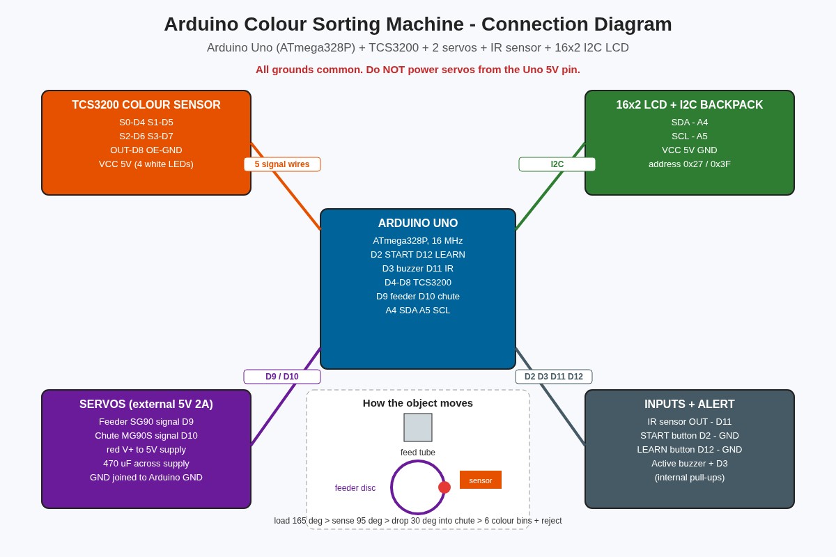
Connection diagram of the Arduino Uno colour sorting machine with TCS3200 colour sensor, feeder and chute servos, IR sensor, buttons, buzzer and 16x2 I2C LCD

Build an Arduino Uno colour sorting machine that feeds objects one by one, reads their colour with a TCS3200 sensor, turns a servo chute to the right bin and counts every colour on a 16×2 LCD, with a learn mode and EEPROM memory.

  • DifficultyAdvanced
  • Build time5–8 hours
  • Board / MCUArduino Uno (ATmega328P)
  • Parts12 items
  • CodeArduino C++

Need it ready-made? Buy Ready Project

Sorting things by colour is a real job in factories: sweets, plastic pellets, pharmacy capsules, beads and even recycled bottle caps are sorted by machines that look at each piece and push it into the right bin. This Arduino colour sorting machine is a desktop version of that idea. You pour objects into a tube, and the machine takes them one at a time, checks the colour, and drops each one into its own cup while the LCD keeps count.

It is a complete combination project: a TCS3200 colour sensor, two servo motors working in sequence, an IR sensor that knows when the tube is empty, two buttons, a buzzer and a 16×2 I2C LCD, all controlled by one ATmega328P. You will learn how a colour sensor turns light into frequency, how to calibrate a sensor with white and black references, nearest-colour matching, smooth servo motion and saving data in EEPROM.

Connection diagram of the Arduino Uno colour sorting machine with TCS3200 colour sensor, feeder and chute servos, IR sensor, buttons, buzzer and 16x2 I2C LCD

How It Works

  • Feeding: the top servo turns a disc with one hole in it. At 165° the hole sits under the feed tube and one object falls in. The disc then turns slowly to 95°, which carries the object under the colour sensor.
  • Presence check: an IR obstacle sensor looks into the hole at the sensing position. If nothing is there, the tube is empty: the machine beeps, shows Tube empty? and pauses until you refill it and press START.
  • Reading the colour: the TCS3200 has an 8×8 grid of photodiodes with red, green, blue and clear filters. Pins S2 and S3 select the filter, and the OUT pin gives a square wave whose frequency rises with the amount of light. The Arduino measures the period of that wave with pulseIn() for each filter, averaging 8 readings.
  • Normalising: raw periods depend on distance and lighting, so the sketch maps each one between your black-card and white-card readings to a value from 0 to 255. This makes the numbers stable and easy to compare.
  • Matching: the reading is compared with six learned reference colours (red, orange, yellow, green, blue and brown) using the sum of the R, G and B differences. The closest colour wins. If even the closest one is more than 60 points away, the object goes to the reject bin.
  • Sorting: the bottom servo turns the chute to the angle for that colour (20° to 170°, seven positions), then the feeder disc turns to 30° and the object drops down the chute into its cup.
  • Counting and memory: each bin has a counter shown on the LCD and printed on the Serial Monitor. Counters and the learned colours are saved in EEPROM, so they are still there after power-off. A long press (2 s) on START resets the counters.

Components Required

  • Arduino Uno R3 or Nano (ATmega328P, 16 MHz) – 1
  • TCS3200 / TCS230 colour sensor module (with 4 white LEDs) – 1
  • SG90 micro servo for the feeder disc – 1
  • MG90S metal-gear servo for the chute – 1
  • IR obstacle sensor module (FC-51 or similar) – 1
  • 16×2 LCD with I2C backpack (PCF8574, address 0x27 or 0x3F) – 1
  • 5 V active buzzer – 1
  • 12 mm tactile push buttons (START and LEARN) – 2
  • 5 V 2 A power supply or LM2596 buck converter for the servos – 1
  • 470 µF 16 V electrolytic capacitor (across the servo supply) – 1
  • Breadboard or perfboard, jumper wires and a white/black calibration card – 1 set
  • Frame: 3 mm MDF, acrylic or 3D-printed parts, a 12 mm feed tube and 7 small cups – 1 set

Wiring Table

Module / pinArduino Uno pinNotes
TCS3200 VCC / GND5V / GNDModule also powers its 4 white LEDs
TCS3200 S0D4HIGH together with S1 LOW = 20 % output scaling
TCS3200 S1D5LOW
TCS3200 S2D6Filter select
TCS3200 S3D7Filter select
TCS3200 OUTD8Square-wave output measured with pulseIn()
TCS3200 OEGNDOutput enable (active LOW); some modules tie it already
Feeder servo SG90 signalD9Red to external 5 V, brown to common GND
Chute servo MG90S signalD10Red to external 5 V, brown to common GND
IR sensor OUTD11VCC 5V, GND; output LOW when an object is in front
START buttonD2Other leg to GND, internal pull-up
LEARN buttonD12Other leg to GND, internal pull-up
Active buzzer +D3Buzzer – to GND (use a buzzer under 30 mA)
LCD I2C SDA / SCLA4 / A5VCC 5V, GND
External 5 V 2 A supply (–)GNDMust be joined to the Arduino GND

Pin check: D9 and D10 both work for servos because the Servo library uses Timer1 on the Uno. That also disables analogWrite() on D9 and D10, which this project does not need. The on-board LED on D13 lights while the machine is running.

Connection Diagram

The diagram above shows how the modules connect to the Arduino and how an object moves through the machine. The drawing below lists every pin exactly as used in the code.

Arduino Colour Sorting Machine – Pin-Accurate Wiring Arduino Uno D2 START button → GND (internal pull-up) D3 Active buzzer (+), buzzer (–) → GND D4 TCS3200 S0 (frequency scale) D5 TCS3200 S1 D6 TCS3200 S2 (filter select) D7 TCS3200 S3 D8 TCS3200 OUT (square wave); OE → GND D9 Feeder servo SG90 signal (orange wire) D10 Chute servo MG90S signal (orange wire) D11 IR obstacle sensor OUT (LOW = object) D12 LEARN button → GND (internal pull-up) A4 / A5 LCD I2C SDA / SCL 5V VCC of TCS3200, IR sensor and LCD only GND Common GND: Uno, sensors, LCD AND servo supply (–) External 5 V 2 A supply (+) → red wire of both servos (–) → servo brown wires + Uno GND 470 µF across (+) and (–) Never power the two servos from the Uno 5V pin: the current spikes reset the board and spoil colour readings. Mount the TCS3200 about 10–15 mm above the feeder hole and shade it from room light with a black tube or box.
Pin-accurate connection diagram for the Arduino colour sorting machine.

Building the Mechanism

  • Feed tube: a 12–15 mm plastic tube or a rolled card tube, a little wider than your objects. Fix it vertically above the feeder disc.
  • Feeder disc: a 50 mm round disc (MDF, acrylic or 3D print) with one hole slightly bigger than one object, screwed to the SG90 horn. Under the disc, a fixed base plate has no hole except at the drop position (30°), so the object rides in the hole until it reaches the chute.
  • Sensor window: mount the TCS3200 looking down on the hole at 95°, 10–15 mm above it, inside a small black shroud so room light does not change the reading. Put the IR sensor at the side of the same position.
  • Chute: a 120 mm half pipe (cut PVC pipe or folded card) glued to the MG90S horn. Arrange 7 cups in a half circle under the end of the chute.
  • Tune the angles: adjust FEED_LOAD, FEED_SENSE, FEED_DROP and CHUTE_ANGLE[] at the top of the sketch to match your build.

Code

Install LiquidCrystal I2C (by Frank de Brabander) from the Library Manager. Servo, Wire and EEPROM come with the Arduino IDE. Select Arduino Uno (or Nano, ATmega328P) and upload. The sketch was compile-checked for the Uno: about 11 KB of flash and 870 bytes of RAM.

/*
  Arduino Colour Sorting Machine
  TCS3200 colour sensor + 2 servos + 16x2 I2C LCD + IR presence sensor + buzzer
  Board: Arduino Uno / Nano (ATmega328P, 16 MHz)
  Arduino Project Hub - ardiunoprojecthub.online - Project #68

  How it works:
   1. The feeder servo picks one object (bead, candy, small block) from the tube
      and carries it under the TCS3200 colour sensor.
   2. The sensor measures red, green, blue and clear light. The sketch compares
      the reading with six learned reference colours (nearest match).
   3. The chute servo turns to the bin for that colour, the feeder drops the
      object, and the LCD shows the colour and the count for each bin.
   4. Counts and learned colours are kept in EEPROM, so they survive power-off.

  Buttons (to GND, internal pull-ups):
   START (D2)  : short press = run / pause, long press (2 s) = reset counters
   LEARN (D12) : hold while powering up = learn mode (teach the 6 colours)
*/

#include <Wire.h>
#include <Servo.h>
#include <EEPROM.h>
#include <LiquidCrystal_I2C.h>

// ---------------- Pin map ----------------
const uint8_t PIN_START  = 2;   // start / pause button
const uint8_t PIN_BUZZER = 3;   // active buzzer (+)
const uint8_t PIN_S0     = 4;   // TCS3200 frequency scaling
const uint8_t PIN_S1     = 5;
const uint8_t PIN_S2     = 6;   // TCS3200 photodiode filter select
const uint8_t PIN_S3     = 7;
const uint8_t PIN_OUT    = 8;   // TCS3200 square-wave output
const uint8_t PIN_FEED   = 9;   // feeder (top) servo signal
const uint8_t PIN_CHUTE  = 10;  // chute (bottom) servo signal
const uint8_t PIN_IR     = 11;  // IR obstacle sensor OUT (LOW = object present)
const uint8_t PIN_LEARN  = 12;  // learn button
const uint8_t PIN_LED    = 13;  // status LED (on-board)

// ---------------- Mechanics (tune for your build) ----------------
const uint8_t FEED_LOAD   = 165;  // feeder hole under the tube
const uint8_t FEED_SENSE  = 95;   // feeder hole under the colour sensor
const uint8_t FEED_DROP   = 30;   // feeder hole over the chute
const uint8_t CHUTE_ANGLE[7] = {20, 45, 70, 95, 120, 145, 170}; // 6 colours + reject bin

// ---------------- Colour table ----------------
const uint8_t NUM_COLOURS = 6;
const char* const COLOUR_NAME[7] = {"Red", "Orange", "Yellow", "Green", "Blue", "Brown", "Reject"};
const uint8_t REJECT = 6;
const uint16_t MATCH_LIMIT = 60;   // larger distance than this = unknown colour

struct Rgb { uint16_t r, g, b; };  // normalised values 0..255 (higher = more of that colour)

// Typical defaults for a TCS3200 at 20% scaling, ~15 mm above the object.
// Run learn mode once for best results with your own lighting and objects.
Rgb ref[NUM_COLOURS] = {
  {190,  60,  70}, {200, 110,  60}, {200, 185,  80},
  { 80, 170,  90}, { 60, 110, 200}, {120,  90,  80}
};

uint16_t binCount[7] = {0};

// ---------------- EEPROM layout ----------------
const uint16_t EE_MAGIC_ADDR = 0;     // 2 bytes
const uint16_t EE_REF_ADDR   = 2;     // 6 x 6 bytes
const uint16_t EE_COUNT_ADDR = 40;    // 7 x 2 bytes
const uint16_t EE_MAGIC      = 0xC068;

LiquidCrystal_I2C lcd(0x27, 16, 2);   // change to 0x3F if your LCD stays blank
Servo feeder, chute;

bool running = false;
uint16_t whiteRef[3] = {0, 0, 0};     // period (us) under white card, for normalising
uint16_t blackRef[3] = {0, 0, 0};     // period (us) under black card

// ---------------- Helpers ----------------
void beep(uint16_t ms) {
  digitalWrite(PIN_BUZZER, HIGH);
  delay(ms);
  digitalWrite(PIN_BUZZER, LOW);
}

void lcdLine(uint8_t row, const char* text) {
  lcd.setCursor(0, row);
  uint8_t n = 0;
  while (text[n] && n < 16) { lcd.write(text[n]); n++; }
  while (n < 16) { lcd.write(' '); n++; }    // clear the rest of the row
}

// Wait for a button press and its release (with debounce). Returns press time in ms.
uint32_t waitPress(uint8_t pin) {
  while (digitalRead(pin) == HIGH) {}
  delay(25);
  uint32_t t0 = millis();
  while (digitalRead(pin) == LOW) {}
  delay(25);
  return millis() - t0;
}

// Move a servo slowly so the object does not jump out of the feeder hole.
void moveSlow(Servo &s, uint8_t target) {
  int pos = s.read();
  int step = (target > pos) ? 1 : -1;
  while (pos != target) {
    pos += step;
    s.write(pos);
    delay(6);
  }
}

// Read one filter channel: average period of the OUT square wave in microseconds.
// Lower period = more light of that colour.
uint16_t readPeriod(bool s2, bool s3) {
  digitalWrite(PIN_S2, s2);
  digitalWrite(PIN_S3, s3);
  delay(5);                                  // let the filter settle
  uint32_t sum = 0;
  uint8_t ok = 0;
  for (uint8_t i = 0; i < 8; i++) {
    uint32_t p = pulseIn(PIN_OUT, LOW, 20000UL);
    if (p > 0) { sum += p; ok++; }
  }
  if (ok == 0) return 0xFFFF;               // no signal: sensor not wired or too dark
  return (uint16_t)(sum / ok);
}

// Raw periods for red, green and blue filters
void readRaw(uint16_t raw[3]) {
  raw[0] = readPeriod(LOW, LOW);      // red filter
  raw[1] = readPeriod(HIGH, HIGH);    // green filter
  raw[2] = readPeriod(LOW, HIGH);     // blue filter
}

// Convert periods to 0..255 using the black and white calibration
Rgb readColour() {
  uint16_t raw[3];
  readRaw(raw);
  uint16_t v[3];
  for (uint8_t i = 0; i < 3; i++) {
    long x = map((long)raw[i], (long)blackRef[i], (long)whiteRef[i], 0L, 255L);
    v[i] = (uint16_t)constrain(x, 0L, 255L);
  }
  Rgb c = {v[0], v[1], v[2]};
  return c;
}

// Nearest reference colour (Manhattan distance). Returns REJECT if nothing is close.
uint8_t classify(const Rgb &c, uint16_t &bestDist) {
  uint8_t best = REJECT;
  bestDist = 0xFFFF;
  for (uint8_t i = 0; i < NUM_COLOURS; i++) {
    uint16_t d = abs((int)c.r - (int)ref[i].r) +
                 abs((int)c.g - (int)ref[i].g) +
                 abs((int)c.b - (int)ref[i].b);
    if (d < bestDist) { bestDist = d; best = i; }
  }
  if (bestDist > MATCH_LIMIT) best = REJECT;
  return best;
}

// ---------------- EEPROM ----------------
void saveCounts() {
  for (uint8_t i = 0; i < 7; i++) EEPROM.put(EE_COUNT_ADDR + i * 2, binCount[i]);
}

void saveRefs() {
  EEPROM.put(EE_MAGIC_ADDR, EE_MAGIC);
  for (uint8_t i = 0; i < NUM_COLOURS; i++) EEPROM.put(EE_REF_ADDR + i * 6, ref[i]);
  // black/white calibration stored after the colour table
  EEPROM.put(EE_REF_ADDR + 36 + 16, whiteRef);
  EEPROM.put(EE_REF_ADDR + 36 + 22, blackRef);
}

bool loadEeprom() {
  uint16_t magic;
  EEPROM.get(EE_MAGIC_ADDR, magic);
  if (magic != EE_MAGIC) return false;
  for (uint8_t i = 0; i < NUM_COLOURS; i++) EEPROM.get(EE_REF_ADDR + i * 6, ref[i]);
  for (uint8_t i = 0; i < 7; i++) {
    EEPROM.get(EE_COUNT_ADDR + i * 2, binCount[i]);
    if (binCount[i] == 0xFFFF) binCount[i] = 0;
  }
  EEPROM.get(EE_REF_ADDR + 36 + 16, whiteRef);
  EEPROM.get(EE_REF_ADDR + 36 + 22, blackRef);
  return true;
}

// ---------------- Learn mode ----------------
// Step 1: white card, step 2: black card, steps 3..8: one sample of each colour.
void learnMode() {
  char buf[17];
  moveSlow(feeder, FEED_SENSE);

  lcdLine(0, "LEARN: put WHITE");
  lcdLine(1, "card, press LRN");
  waitPress(PIN_LEARN);
  readRaw(whiteRef);
  beep(60);

  lcdLine(0, "LEARN: put BLACK");
  lcdLine(1, "card, press LRN");
  waitPress(PIN_LEARN);
  readRaw(blackRef);
  beep(60);

  for (uint8_t i = 0; i < NUM_COLOURS; i++) {
    snprintf(buf, sizeof(buf), "LEARN: %s", COLOUR_NAME[i]);
    lcdLine(0, buf);
    lcdLine(1, "place, press LRN");
    waitPress(PIN_LEARN);
    // average three readings for a stable reference
    uint32_t r = 0, g = 0, b = 0;
    for (uint8_t k = 0; k < 3; k++) {
      Rgb c = readColour();
      r += c.r; g += c.g; b += c.b;
    }
    ref[i].r = r / 3; ref[i].g = g / 3; ref[i].b = b / 3;
    snprintf(buf, sizeof(buf), "R%3u G%3u B%3u", ref[i].r, ref[i].g, ref[i].b);
    lcdLine(1, buf);
    beep(60);
    delay(800);
  }
  saveRefs();
  lcdLine(0, "Colours saved!");
  lcdLine(1, "Press START");
  beep(200);
}

// ---------------- Display ----------------
void showIdle() {
  char buf[17];
  uint16_t total = 0;
  for (uint8_t i = 0; i < 7; i++) total += binCount[i];
  lcdLine(0, running ? "RUNNING" : "PAUSED - START");
  snprintf(buf, sizeof(buf), "Total sorted %u", total);
  lcdLine(1, buf);
}

// ---------------- Sort one object ----------------
void sortOne() {
  char buf[17];

  // 1. pick up an object from the tube
  moveSlow(feeder, FEED_LOAD);
  delay(400);

  // 2. carry it under the sensor
  moveSlow(feeder, FEED_SENSE);
  delay(300);

  // 3. is there really an object? (IR sensor looks into the feeder hole)
  if (digitalRead(PIN_IR) == HIGH) {
    lcdLine(0, "Tube empty?");
    lcdLine(1, "Refill & START");
    beep(400);
    running = false;
    return;
  }

  // 4. read and classify the colour
  Rgb c = readColour();
  uint16_t dist;
  uint8_t bin = classify(c, dist);

  snprintf(buf, sizeof(buf), "%-7s d=%u", COLOUR_NAME[bin], dist);
  lcdLine(0, buf);
  snprintf(buf, sizeof(buf), "R%3u G%3u B%3u", c.r, c.g, c.b);
  lcdLine(1, buf);

  Serial.print(F("RGB "));
  Serial.print(c.r); Serial.print(' ');
  Serial.print(c.g); Serial.print(' ');
  Serial.print(c.b);
  Serial.print(F(" -> "));
  Serial.println(COLOUR_NAME[bin]);

  // 5. turn the chute, then drop the object
  moveSlow(chute, CHUTE_ANGLE[bin]);
  delay(150);
  moveSlow(feeder, FEED_DROP);
  delay(350);

  binCount[bin]++;
  saveCounts();                // EEPROM.put only writes bytes that changed
  if (bin == REJECT) beep(150);

  snprintf(buf, sizeof(buf), "%s bin: %u", COLOUR_NAME[bin], binCount[bin]);
  lcdLine(1, buf);
}

// ---------------- Setup / loop ----------------
void setup() {
  Serial.begin(9600);
  pinMode(PIN_START, INPUT_PULLUP);
  pinMode(PIN_LEARN, INPUT_PULLUP);
  pinMode(PIN_IR, INPUT);
  pinMode(PIN_BUZZER, OUTPUT);
  pinMode(PIN_LED, OUTPUT);
  pinMode(PIN_S0, OUTPUT); pinMode(PIN_S1, OUTPUT);
  pinMode(PIN_S2, OUTPUT); pinMode(PIN_S3, OUTPUT);
  pinMode(PIN_OUT, INPUT);
  digitalWrite(PIN_S0, HIGH);  // 20% output frequency scaling (S0=H, S1=L)
  digitalWrite(PIN_S1, LOW);

  lcd.init();
  lcd.backlight();

  feeder.attach(PIN_FEED);
  chute.attach(PIN_CHUTE);
  feeder.write(FEED_SENSE);
  chute.write(CHUTE_ANGLE[3]);

  bool haveData = loadEeprom();
  if (!haveData) {
    // first power-up: sensible default periods (white ~ 40 us, black ~ 400 us)
    for (uint8_t i = 0; i < 3; i++) { whiteRef[i] = 40; blackRef[i] = 400; }
    for (uint8_t i = 0; i < 7; i++) binCount[i] = 0;
    saveRefs();            // write defaults so counts are kept from now on
    saveCounts();
  }

  lcdLine(0, "Colour Sorter");
  lcdLine(1, haveData ? "Data loaded" : "Defaults - LEARN");
  beep(80);
  delay(1200);

  if (digitalRead(PIN_LEARN) == LOW) {   // LEARN held at power-up
    while (digitalRead(PIN_LEARN) == LOW) {}
    delay(50);
    learnMode();
  }
  showIdle();
}

void loop() {
  // START button: short press toggles run/pause, long press resets the counters
  if (digitalRead(PIN_START) == LOW) {
    uint32_t held = waitPress(PIN_START);
    if (held > 2000) {
      for (uint8_t i = 0; i < 7; i++) binCount[i] = 0;
      saveCounts();
      running = false;
      lcdLine(0, "Counters reset");
      beep(300);
      delay(1000);
    } else {
      running = !running;
      beep(40);
    }
    showIdle();
  }

  digitalWrite(PIN_LED, running);
  if (running) {
    sortOne();
    if (!running) showIdle();
  }
}

Calibration and Testing

  • Learn mode: hold the LEARN button while you power up (or press reset), then release it. The LCD asks for a white card, then a black card, then one sample of each of the six colours. Place each one in the feeder hole under the sensor and press LEARN. The values are saved in EEPROM.
  • Check readings: open the Serial Monitor at 9600 baud. Each sorted object prints a line like RGB 192 64 71 -> Red. If two colours give very similar numbers (for example orange and brown), run learn mode again with better shading.
  • Run: press START to begin. The LED on D13 lights and the machine sorts about one object every 2–3 seconds. Press START again to pause; hold it for 2 seconds to reset the counters.
  • Tune the reject limit: raise MATCH_LIMIT if too many good objects go to reject, lower it if wrong colours slip into a bin.

Troubleshooting

ProblemFix
LCD backlight is on but no textTurn the blue contrast pot on the I2C backpack. If still blank, change the address in the sketch from 0x27 to 0x3F.
Arduino resets when the servos moveThe servos are drawing current from the Uno. Power them from a separate 5 V 2 A supply, join the grounds and add the 470 µF capacitor.
All readings are 0 or 255OUT is not reaching D8 or OE is not tied to GND. Check S0 to S3 wiring and that the four white LEDs on the module are lit.
Colour changes with room lightShade the sensor with a black tube or box and run learn mode again in the same lighting.
Every object goes to rejectLearn mode was skipped and the defaults do not match your objects. Hold LEARN at power-up and teach all six colours.
Machine says Tube empty? with objects presentAdjust the IR sensor’s blue trim pot until its LED turns on only when an object is in the hole. Matt black objects may need the sensor moved closer.
Objects jam between disc and baseMake the hole 1–2 mm bigger than the object and sand the edges. The slow servo movement in the code also helps.
Chute misses the cupsChange the values in CHUTE_ANGLE[] in 5° steps until each object lands in the middle of its cup.

Ideas to Extend

  • Add an HC-05 Bluetooth module to send the counts to a phone.
  • Replace the SG90 feeder with a small stepper motor for faster, more precise feeding.
  • Add a seventh learned colour (purple or white) by using the reject position as a real bin.

ATmega16 Fire & Gas Safety System with MQ-2, Flame Sensor, LCD & Exhaust Fan

ATmega16 fire and gas safety system on a breadboard with MQ-2 gas sensor, flame sensor, LM35, 16x2 LCD showing SAFE, 2-channel relay with exhaust fan, buzzer, red and green LEDs and push button

Build an ATmega16 fire and gas safety system that watches an MQ-2 gas/smoke sensor, an IR flame sensor and an LM35 temperature sensor, shows the status on a 16×2 LCD, switches on an exhaust fan, closes a gas valve relay and sounds a latched alarm.

  • DifficultyAdvanced
  • Build time5–6 hours
  • Board / MCUATmega16 (8 MHz internal)
  • Parts15 items
  • CodeEmbedded C (AVR-GCC)

Need it ready-made? Buy Ready Project

This ATmega16 fire and gas safety system is a complete kitchen and workshop safety controller built around one 40-pin AVR chip. It watches three sensors at the same time: an MQ-2 module for LPG, smoke and other combustible gases, an IR flame sensor that sees an open flame, and an LM35 for room temperature. A 16×2 LCD shows the live gas level, temperature and system state, while a 2-channel relay module drives an exhaust fan and a gas solenoid valve (or a mains cut-off contactor).

When gas starts to build up, the fan switches on automatically and the buzzer gives a slow warning beep. If there is a flame, heavy gas or smoke, or a very high temperature, the system goes into a latched ALARM: the fan runs, the valve relay closes the gas supply, the red LED flashes and the buzzer sounds fast. The alarm stays on until the danger is gone and someone presses the RESET button, just like a real fire panel. It is a big combination project that teaches multi-channel ADC, sensor calibration, state machines, relay control and 4-bit LCD driving in plain AVR C.

Safety note: this is a learning project, not a certified gas or fire detector. Keep a certified smoke and LPG alarm installed, and let a qualified electrician do any 230V mains wiring.

ATmega16 fire and gas safety system on a breadboard with MQ-2 gas sensor, flame sensor, LM35, 16x2 LCD showing SAFE, 2-channel relay with exhaust fan, buzzer, red and green LEDs and push button

How It Works

  • Warm-up and auto-calibration: the MQ-2 heater needs about a minute to stabilise, so the LCD counts down 60 seconds while the LEDs blink. The ATmega16 then averages 200 readings from ADC0 in clean air and stores this as the baseline. All gas readings are shown as a rise above the baseline (for example Gas:+35), which makes the project work with any MQ-2 module.
  • Gas and smoke (PA0): the MQ-2 tin-dioxide element lowers its resistance when LPG, methane, propane, hydrogen or smoke reaches it, so the AOUT voltage rises. 16 samples are averaged every 100 ms to remove noise.
  • Temperature (PA1): the LM35 outputs 10 mV per °C. With the 5V AVCC reference each ADC step is about 4.9 mV, so the code converts it with temp = raw × 500 / 1023.
  • Flame (PD2): the flame module’s comparator output goes LOW when it sees the infrared light from a flame. The internal pull-up keeps the line HIGH otherwise.
  • Three states: SAFE (green LED, relays off), WARNING (gas rise of 80+ counts or 45 °C+: fan on and a slow beep) and ALARM (flame, gas rise of 220+ counts or 60 °C+: fan on, valve relay on, red LED flashing and a fast beep). All limits are #define values at the top of the code.
  • Latched alarm and silence: during an alarm, one press of the button mutes the buzzer for 60 seconds (an M appears on the LCD). After the sensors return to normal the alarm stays latched until you press the button again, so nobody misses a short event.
  • Fan run-on: after gas clears, the exhaust fan keeps running for 30 more seconds to push the remaining gas out of the room.

Components Required

  • ATmega16 microcontroller (40-pin DIP) – 1
  • USBasp programmer (10-pin to 6-pin adapter if needed) – 1
  • MQ-2 gas/smoke sensor module (with AOUT pin) – 1
  • IR flame sensor module (3-pin, DO output) – 1
  • LM35 temperature sensor (TO-92) – 1
  • 16×2 character LCD (HD44780) with 10 kΩ contrast pot – 1
  • 2-channel 5V relay module (opto-isolated) – 1
  • 12V DC exhaust fan (or small 5V fan for the demo) – 1
  • 12V solenoid gas valve (or any load for the demo) – 1
  • Active buzzer 5V + 2N2222 transistor + 1 kΩ resistor – 1 set
  • Red and green 5 mm LEDs with 220 Ω resistors – 1 each
  • Tactile push button (SILENCE / RESET) – 1
  • 10 kΩ resistor (RESET pull-up) and 100 nF capacitors – 1 and 3
  • 12V 2A adapter + LM7805 regulator (or 5V 2A supply) – 1
  • Large breadboard or perfboard and jumper wires – 1 set

Wiring Table

Part / pinATmega16 pinNotes
7805 output +5VVCC (10), AVCC (30)100 nF from each to GND; AREF (32) 100 nF to GND
GNDGND (11, 31)Common ground for sensors, relay module, LCD and 12V supply
RESETPin 910 kΩ to +5V (also to USBasp RESET)
MQ-2 AOUTPA0 / ADC0 (40)MQ-2 VCC to +5V (heater draws about 150 mA)
LM35 Vout (middle pin)PA1 / ADC1 (39)Left pin +5V, right pin GND (flat face towards you)
Flame sensor DOPD2 (16)Module VCC +5V, GND; set sensitivity with its blue pot
SILENCE / RESET buttonPD3 (17) and GNDInternal pull-up, no resistor needed
LCD RS / RW / ENPB0 (1) / GND / PB1 (2)LCD VSS GND, VDD +5V, V0 to 10 kΩ pot wiper
LCD D4, D5, D6, D7PB4, PB5, PB6, PB7 (5–8)D0–D3 unused; backlight A via 220 Ω to +5V, K to GND
Relay IN1 (exhaust fan)PC0 (22)Fan +12V through relay COM/NO
Relay IN2 (gas valve / cut-off)PC1 (23)Valve +12V through relay COM/NO
Relay module VCC / GND+5V / GNDActive-LOW inputs; set RELAY_ACTIVE_LOW 0 for active-HIGH boards
Buzzer driverPD5 (19)1 kΩ to 2N2222 base, emitter GND, buzzer between +5V and collector
Red ALARM LEDPD6 (20)Through 220 Ω, cathode to GND
Green SAFE LEDPD7 (21)Through 220 Ω, cathode to GND

Fuses: the code runs on the internal 8 MHz oscillator with JTAG disabled so all of PORTC is free: lfuse = 0xE4, hfuse = 0xD9. A fresh ATmega16 has JTAG enabled, which blocks PC2–PC5, so always set the fuses first.

Connection Diagram

The illustration above shows the parts laid out on a breadboard. It is a layout guide only, so follow the pin-accurate drawing below, which matches the wiring table.

ATmega16 Fire & Gas Safety System – Pin-Accurate Wiring ATmega16 VCC/AVCC (10,30) +5V from 7805; AREF (32) via 100 nF to GND GND (11,31) Common GND for all modules and supplies PA0 / ADC0 (40) MQ-2 module AOUT PA1 / ADC1 (39) LM35 middle pin (Vout) PB0 (1) LCD RS (pin 4); LCD RW (pin 5) to GND PB1 (2) LCD EN (pin 6) PB4-PB7 (5-8) LCD D4-D7 (pins 11-14) PC0 (22) Relay IN1 – exhaust fan PC1 (23) Relay IN2 – gas valve / cut-off PD2 / INT0 (16) Flame sensor DO (LOW = flame) PD3 (17) SILENCE/RESET button to GND PD5 (19) 1 kΩ to 2N2222 base; buzzer on collector PD6 (20) 220 Ω to red ALARM LED PD7 (21) 220 Ω to green SAFE LED RESET (9): 10 kΩ to +5V. Program with USBasp: MOSI PB5, MISO PB6, SCK PB7, RESET.
Pin-accurate connection diagram for the ATmega16 fire and gas safety system.

Code

The firmware is plain AVR C with no external libraries (about 1.9 KB of flash). Save it as main.c, then compile and flash it with avr-gcc and a USBasp:

avr-gcc -mmcu=atmega16 -Os -o main.elf main.c
avr-objcopy -O ihex -R .eeprom main.elf main.hex
avrdude -c usbasp -p m16 -U lfuse:w:0xE4:m -U hfuse:w:0xD9:m
avrdude -c usbasp -p m16 -U flash:w:main.hex:i

You can also use Microchip Studio: create a GCC C project for the ATmega16, paste the code and build. Keep F_CPU at 8000000 to match the fuses.

/*
 * ATmega16 Fire & Gas Safety System
 * MQ-2 gas/smoke sensor + IR flame sensor + LM35 temperature sensor,
 * 16x2 LCD, 2-channel relay (exhaust fan + gas valve / mains cut-off),
 * buzzer, LEDs and a SILENCE / RESET button.
 * ardiunoprojecthub.online
 *
 * MCU   : ATmega16 @ 8 MHz internal oscillator
 * Fuses : lfuse=0xE4 (internal 8 MHz), hfuse=0xD9 (JTAG off so PORTC is free)
 *
 * Pins
 *   MQ-2 AOUT        -> PA0 (ADC0)
 *   LM35 Vout        -> PA1 (ADC1)
 *   Flame sensor DO  -> PD2 (LOW = flame seen, internal pull-up on)
 *   SILENCE button   -> PD3 to GND (internal pull-up)
 *   LCD 16x2 4-bit   : RS=PB0, EN=PB1, D4=PB4, D5=PB5, D6=PB6, D7=PB7, RW=GND
 *   Relay CH1 (fan)  -> PC0
 *   Relay CH2 (valve)-> PC1
 *   Buzzer (active)  -> PD5 (via 2N2222 or direct if < 20 mA)
 *   Red LED ALARM    -> PD6 (220 ohm)
 *   Green LED SAFE   -> PD7 (220 ohm)
 *   AVCC -> 5V, AREF -> 100 nF to GND (AVCC used as ADC reference)
 *
 * States
 *   SAFE    : green LED, relays off.
 *   WARNING : gas rising or temperature high -> exhaust fan ON, slow beep.
 *   ALARM   : flame, heavy gas/smoke or very high temperature ->
 *             fan ON, gas valve relay CLOSES supply, fast beep, red LED.
 *   ALARM is latched: once conditions are safe again, press SILENCE/RESET
 *   to return to SAFE. While in ALARM, SILENCE mutes the buzzer for 60 s.
 */
#define F_CPU 8000000UL
#include <avr/io.h>
#include <util/delay.h>
#include <stdint.h>
#include <stdlib.h>

/* ---------- user settings ---------- */
#define WARMUP_S        60     /* MQ-2 heater warm-up time            */
#define GAS_WARN_DELTA  80     /* ADC counts above clean-air baseline */
#define GAS_ALARM_DELTA 220
#define TEMP_WARN_C     45
#define TEMP_ALARM_C    60
#define FAN_RUNON_S     30     /* fan keeps running after gas clears  */
#define SILENCE_S       60
#define RELAY_ACTIVE_LOW 1     /* most blue relay modules are active-LOW */

/* ---------- LCD (HD44780 4-bit on PORTB) ---------- */
#define LCD_RS PB0
#define LCD_EN PB1

static void lcd_pulse(void)
{
    PORTB |= (1 << LCD_EN); _delay_us(1);
    PORTB &= ~(1 << LCD_EN); _delay_us(50);
}
static void lcd_nibble(uint8_t n)
{
    PORTB = (PORTB & 0x0F) | (n & 0xF0);
    lcd_pulse();
}
static void lcd_byte(uint8_t b, uint8_t rs)
{
    if (rs) PORTB |= (1 << LCD_RS); else PORTB &= ~(1 << LCD_RS);
    lcd_nibble(b);
    lcd_nibble(b << 4);
    if (!rs && b < 4) _delay_ms(2);
}
static void lcd_cmd(uint8_t c)  { lcd_byte(c, 0); }
static void lcd_char(char c)    { lcd_byte((uint8_t)c, 1); }
static void lcd_goto(uint8_t col, uint8_t row) { lcd_cmd(0x80 | (row ? 0x40 : 0x00) | col); }
static void lcd_print(const char *s) { while (*s) lcd_char(*s++); }
static void lcd_line(uint8_t row, const char *s)
{   /* print a full 16-char line, padding with spaces (no flicker) */
    uint8_t i = 0;
    lcd_goto(0, row);
    while (*s && i < 16) { lcd_char(*s++); i++; }
    while (i++ < 16) lcd_char(' ');
}
static void lcd_init(void)
{
    DDRB |= 0xF3;                 /* PB0, PB1, PB4..PB7 outputs */
    _delay_ms(50);
    PORTB &= ~(1 << LCD_RS);
    lcd_nibble(0x30); _delay_ms(5);
    lcd_nibble(0x30); _delay_us(150);
    lcd_nibble(0x30); _delay_us(150);
    lcd_nibble(0x20);             /* 4-bit mode */
    lcd_cmd(0x28);                /* 2 lines, 5x8 font */
    lcd_cmd(0x0C);                /* display on, cursor off */
    lcd_cmd(0x06);                /* entry mode */
    lcd_cmd(0x01);                /* clear */
}

/* ---------- ADC ---------- */
static void adc_init(void)
{
    ADMUX  = (1 << REFS0);                                 /* AVCC ref */
    ADCSRA = (1 << ADEN) | (1 << ADPS2) | (1 << ADPS1);    /* 8 MHz/64 = 125 kHz */
}
static uint16_t adc_read(uint8_t ch)
{
    ADMUX = (1 << REFS0) | (ch & 0x07);
    _delay_us(20);
    ADCSRA |= (1 << ADSC);
    while (ADCSRA & (1 << ADSC));
    return ADC;
}
static uint16_t adc_avg(uint8_t ch, uint8_t n)
{
    uint32_t sum = 0;
    for (uint8_t i = 0; i < n; i++) sum += adc_read(ch);
    return (uint16_t)(sum / n);
}

/* ---------- outputs ---------- */
static void relay(uint8_t pin, uint8_t on)
{
#if RELAY_ACTIVE_LOW
    if (on) PORTC &= ~(1 << pin); else PORTC |= (1 << pin);
#else
    if (on) PORTC |= (1 << pin); else PORTC &= ~(1 << pin);
#endif
}
#define FAN   PC0
#define VALVE PC1
#define BUZ_ON()   (PORTD |=  (1 << PD5))
#define BUZ_OFF()  (PORTD &= ~(1 << PD5))
#define RED(x)     ((x) ? (PORTD |= (1 << PD6)) : (PORTD &= ~(1 << PD6)))
#define GREEN(x)   ((x) ? (PORTD |= (1 << PD7)) : (PORTD &= ~(1 << PD7)))
#define FLAME_SEEN()   (!(PIND & (1 << PD2)))
#define BTN_PRESSED()  (!(PIND & (1 << PD3)))

enum { SAFE, WARNING, ALARM };

static void beep(uint16_t ms) { BUZ_ON(); while (ms--) _delay_ms(1); BUZ_OFF(); }

int main(void)
{
    char num[7];

    /* I/O setup */
    DDRC |= (1 << FAN) | (1 << VALVE);
    relay(FAN, 0); relay(VALVE, 0);
    DDRD |= (1 << PD5) | (1 << PD6) | (1 << PD7);
    DDRD &= ~((1 << PD2) | (1 << PD3));
    PORTD |= (1 << PD2) | (1 << PD3);           /* pull-ups */

    lcd_init();
    adc_init();

    /* ---- warm-up of the MQ-2 heater ---- */
    lcd_line(0, "Fire&Gas Safety");
    for (int s = WARMUP_S; s > 0; s--) {
        itoa(s, num, 10);
        lcd_line(1, "");
        lcd_goto(0, 1); lcd_print("Warm-up "); lcd_print(num); lcd_print(" s");
        RED(s & 1); GREEN(!(s & 1));
        _delay_ms(1000);
    }

    /* ---- learn clean-air baseline ---- */
    lcd_line(1, "Calibrating...");
    uint32_t sum = 0;
    for (uint16_t i = 0; i < 200; i++) { sum += adc_read(0); _delay_ms(5); }
    uint16_t baseline = (uint16_t)(sum / 200);
    RED(0); GREEN(1);
    beep(100);

    uint8_t  state = SAFE, latched = 0;
    uint16_t fan_runon = 0, silence = 0;   /* in 100 ms ticks */
    uint8_t  tick = 0, btn_prev = 0;

    for (;;) {
        /* ---- read sensors (every 100 ms) ---- */
        uint16_t gas  = adc_avg(0, 16);
        int16_t  diff = (int16_t)gas - (int16_t)baseline;
        if (diff < 0) diff = 0;
        uint16_t traw = adc_avg(1, 16);
        int16_t  temp = (int16_t)((traw * 500UL) / 1023);   /* LM35: 10 mV/C */
        uint8_t  flame = FLAME_SEEN();

        /* ---- decide state ---- */
        uint8_t now;
        if (flame || diff >= GAS_ALARM_DELTA || temp >= TEMP_ALARM_C) now = ALARM;
        else if (diff >= GAS_WARN_DELTA || temp >= TEMP_WARN_C)      now = WARNING;
        else                                                          now = SAFE;

        if (now == ALARM) { latched = 1; }
        if (latched) state = ALARM; else state = now;

        /* ---- button: silence buzzer or reset latched alarm ---- */
        uint8_t btn = BTN_PRESSED();
        if (btn && !btn_prev) {
            if (latched && now != ALARM) { latched = 0; state = now; silence = 0; beep(60); }
            else if (state == ALARM) { silence = SILENCE_S * 10; }
        }
        btn_prev = btn;
        if (silence) silence--;

        /* ---- outputs ---- */
        if (state != SAFE || diff >= GAS_WARN_DELTA) fan_runon = FAN_RUNON_S * 10;
        else if (fan_runon) fan_runon--;
        relay(FAN, fan_runon > 0);
        relay(VALVE, state == ALARM);           /* close gas / cut supply */

        GREEN(state == SAFE);
        if (state == ALARM)        { RED(tick & 2); if (!silence && (tick & 2)) BUZ_ON(); else BUZ_OFF(); }
        else if (state == WARNING) { RED(tick < 2); if (tick == 0) BUZ_ON(); else BUZ_OFF(); }
        else                       { RED(0); BUZ_OFF(); }

        /* ---- LCD every 500 ms ---- */
        if (tick % 5 == 0) {
            const char *msg;
            if (state == ALARM)
                msg = flame ? "!! FIRE ALARM !!" : (diff >= GAS_ALARM_DELTA ? "!! GAS  ALARM !!" :
                      (temp >= TEMP_ALARM_C ? "!! HEAT ALARM !!" : "ALARM-press RST "));
            else if (state == WARNING) msg = "WARNING  Fan ON ";
            else msg = fan_runon ? "SAFE    Fan ON  " : "SAFE  All normal";
            lcd_line(0, msg);

            /* line 2: "Gas:+123 T:31C F" */
            itoa(diff, num, 10);
            lcd_goto(0, 1);
            lcd_print("Gas:+"); lcd_print(num); lcd_print("   ");
            lcd_goto(9, 1);
            itoa(temp, num, 10);
            lcd_print("T:"); lcd_print(num); lcd_print("C");
            lcd_print(temp < 10 ? "  " : (temp < 100 ? " " : ""));
            lcd_goto(15, 1);
            lcd_char(flame ? 'F' : (silence ? 'M' : ' '));
        }

        if (++tick >= 10) tick = 0;
        _delay_ms(100 - 20);   /* ~100 ms loop including ADC time */
    }
}

Testing and Calibration

  • Power up in clean air. After the warm-up the LCD should read SAFE All normal with a gas value close to +0 and the room temperature.
  • Gas test: hold an unlit lighter near the MQ-2 and press its gas button briefly (do not light it). The gas value rises, the fan relay clicks on (WARNING) and, with more gas, the system goes to GAS ALARM and the valve relay turns on.
  • Flame test: light a candle about 30–50 cm in front of the flame sensor. Its DO LED lights and the LCD shows FIRE ALARM. Adjust the module’s pot so normal room light does not trigger it.
  • Heat test: warm the LM35 gently with your fingers or a hair dryer on low to see the temperature go up; lower TEMP_WARN_C temporarily to test the warning.
  • Press the button during an alarm to mute it, then again after the reading is normal to reset. Tune GAS_WARN_DELTA and GAS_ALARM_DELTA to suit your room.

Troubleshooting

ProblemFix
LCD shows black boxes or nothingTurn the 10 kΩ contrast pot. Check RW is tied to GND and the D4–D7 lines go to PB4–PB7 in order.
LCD garbled or code runs very slowlyThe fuses are still at 1 MHz or the clock does not match F_CPU. Program lfuse 0xE4 and hfuse 0xD9.
Relays click the wrong way (on when SAFE)Your relay board is active-HIGH. Change RELAY_ACTIVE_LOW to 0 and rebuild.
Goes to GAS ALARM right after startIt calibrated in dirty air or the MQ-2 is new. Burn in a new sensor for 24–48 hours, then reset the ATmega16 in fresh air.
FIRE ALARM in sunlight or bright lampSunlight contains infrared. Turn the flame module’s pot to lower sensitivity and point it away from windows.
Temperature reads 0 or jumps a lotCheck the LM35 pin order and add a 100 nF capacitor from its output to GND. Keep its wires away from the relay wires.
Controller resets when the fan or valve switchesFeed the 12V loads from their own supply, keep only GND common, add a flyback diode across the solenoid valve and a 470 µF capacitor on the 5V rail.

Ideas to Extend

  • Add a SIM800L GSM module on the ATmega16 UART (PD0/PD1) to send an SMS on alarm.
  • Log alarm events with a time stamp using a DS1307 RTC and the internal EEPROM.
  • Add a second MQ-2 in another room on ADC2 and show which zone is in alarm.

ATmega1284P Fingerprint Door Lock with R307, Keypad, OLED & Relay

ATmega1284P fingerprint door lock on a breadboard with R307 fingerprint sensor, 4x4 keypad, OLED display, relay module, solenoid lock, exit button, buzzer and LEDs

Build an ATmega1284P fingerprint door lock that opens with a stored fingerprint or a 6-digit keypad PIN, shows status on an OLED and drives a 12V solenoid lock through a relay.

  • DifficultyAdvanced
  • Build time5–8 hours
  • Board / MCUATmega1284P (16 MHz, MightyCore)
  • Parts15 items
  • CodeArduino C++

Need it ready-made? Buy Ready Project

This ATmega1284P fingerprint door lock is a complete access-control system for a home, lab or office door. It opens with any enrolled fingerprint or with a 6-digit PIN typed on a 4×4 keypad, then drives a 12V solenoid lock through a relay for five seconds and locks again by itself.

It combines several modules in one build: an R307 optical fingerprint sensor, a keypad, an OLED status screen, a relay, a reed sensor that warns when the door is left open, an inside exit button, a buzzer and two status LEDs. The ATmega1284P is a good fit because it has two hardware UARTs (one for the fingerprint sensor and one free for debugging), 128 KB of flash and 16 KB of RAM, all in a breadboard-friendly 40-pin DIP package.

ATmega1284P fingerprint door lock on a breadboard with R307 fingerprint sensor, 4x4 keypad, OLED display, relay module, solenoid lock, exit button, buzzer and LEDs

How It Works

  • Fingerprint check: the loop keeps asking the R307 for an image. When a finger is placed, the sensor turns it into a template and searches its own on-board library (up to 127 prints in this code). A match with a confidence score of 50 or more unlocks the door and the OLED shows which ID opened it.
  • PIN entry: digits typed on the keypad show as stars. # confirms and * clears. The PIN is kept in the chip’s EEPROM, so it survives power cuts. The first-boot PIN is 123456, so change it straight away.
  • Admin menu: A enrolls a new finger (two scans of the same finger), B deletes a stored ID, C changes the PIN and D shows how many prints are stored. A, B and C all ask for the current PIN first.
  • Lockout: three wrong fingers or PINs in a row lock the keypad and sensor for 30 seconds with a long beep, which slows down guessing.
  • Relay and auto re-lock: PB0 switches the relay, which feeds 12V to the solenoid for 5 seconds. A 1N4007 diode across the coil absorbs the voltage spike when it switches off.
  • Exit button and door sensor: the inside exit button always opens the door, even during lockout. The reed switch reads HIGH when the door is open, and if it stays open for more than 30 seconds the buzzer beeps and the OLED asks you to close it.

Components Required

  • ATmega1284P (40-pin DIP) microcontroller – 1
  • 16 MHz crystal with two 22 pF capacitors – 1 set
  • R307 or AS608 optical fingerprint sensor module – 1
  • 4×4 membrane keypad – 1
  • 0.96 inch SSD1306 I2C OLED display (128×64) – 1
  • 5V single-channel relay module (with transistor driver and diode) – 1
  • 12V solenoid door lock (or electric strike) with 1N4007 flyback diode – 1
  • Magnetic reed door sensor – 1
  • Exit push button (inside of the door) – 1
  • 5V active buzzer – 1
  • Green and red LEDs with 220 Ω resistors – 1 each
  • 10 kΩ resistor (RESET pull-up) and 100 nF decoupling capacitors – 1 + 3
  • 12V 2A adapter and LM2596 buck module (or 7805) set to 5V – 1 each
  • USBasp programmer and USB-to-TTL serial adapter (for debug) – 1 each
  • Breadboard or perfboard, jumper wires and screw terminals – 1 set

Wiring Table

Part / pinATmega1284P pinNotes
Fingerprint TX (green wire on most R307)RXD1 / PD2 (pin 16)Arduino pin 10 in MightyCore standard pinout
Fingerprint RX (white wire on most R307)TXD1 / PD3 (pin 17)Arduino pin 11
Fingerprint VCC / GND5V / GNDAS608 modules need 3.3V, check your module
Keypad rows R1, R2, R3, R4PA0, PA1, PA2, PA3 (pins 40 to 37)Arduino pins 24 to 27
Keypad columns C1, C2, C3, C4PA4, PA5, PA6, PA7 (pins 36 to 33)Arduino pins 28 to 31
OLED SCL / SDAPC0 (pin 22) / PC1 (pin 23)I2C address 0x3C
Relay INPB0 (pin 1)Arduino pin 0, active HIGH relay module
Relay COM / NO+12V / solenoid +Solenoid – to 12V supply GND, 1N4007 across the coil
Active buzzer +PB1 (pin 2)Buzzer – to GND
Green LED (unlocked)PB2 (pin 3) through 220 ΩCathode to GND
Red LED (locked)PB3 (pin 4) through 220 ΩCathode to GND
Reed door sensorPB4 (pin 5)Other wire to GND, internal pull-up, LOW = door closed
Exit buttonPD4 (pin 18)Other leg to GND, internal pull-up
USB-TTL adapter (debug)RXD0 PD0 (pin 14) / TXD0 PD1 (pin 15)115200 baud, optional
16 MHz crystalXTAL2 (pin 12) / XTAL1 (pin 13)22 pF from each pin to GND
VCC / AVCC / GNDPins 10, 30 / pins 11, 315V from the buck module, 100 nF at each VCC pin
RESETPin 910 kΩ to 5V, also to the USBasp RST line

Keep the 12V lock wiring away from the logic side and join only the grounds of the 12V supply and the 5V buck output. Never power the solenoid from the 5V rail.

Connection Diagram

The illustration above shows the parts laid out on a bench. It is a layout guide only. Follow the pin-accurate drawing below, which matches the wiring table exactly.

ATmega1284P Fingerprint Door Lock – Pin-Accurate Wiring Power 5V to VCC (pin 10) and AVCC (pin 30), GND to pins 11 and 31 16 MHz crystal on XTAL1/XTAL2 (pins 13, 12), 22 pF to GND 10 kΩ RESET (pin 9) to 5V, 100 nF at each VCC pin Fingerprint R307 Sensor TX to RXD1 / PD2 (pin 16) Sensor RX to TXD1 / PD3 (pin 17) VCC 5V (3.3V for AS608), GND to GND 4×4 keypad Rows R1-R4 to PA0-PA3 (pins 40 to 37) Columns C1-C4 to PA4-PA7 (pins 36 to 33) OLED SSD1306 SCL to PC0 (pin 22), SDA to PC1 (pin 23) VCC 5V (module has a regulator), GND to GND Relay + lock Relay IN to PB0 (pin 1), VCC 5V, GND COM to +12V, NO to solenoid +, solenoid – to 12V GND 1N4007 across the solenoid (band to +) Inputs + signals Reed switch PB4 (pin 5) to GND, exit button PD4 (pin 18) to GND Buzzer + PB1 (pin 2), green LED PB2 (pin 3), red LED PB3 (pin 4) via 220 Ω
Pin-accurate connection diagram for the ATmega1284P fingerprint door lock.

Arduino Code

Install MightyCore in the Arduino IDE (Boards Manager URL https://mcudude.github.io/MightyCore/package_MCUdude_MightyCore_index.json), then pick ATmega1284, variant 1284P, pinout Standard and clock 16 MHz external. Install the Adafruit Fingerprint Sensor Library, Keypad (Mark Stanley, Alexander Brevig), Adafruit SSD1306 and Adafruit GFX libraries. Click Burn Bootloader once with the USBasp to set the fuses, then use Upload Using Programmer. The sketch below was compiled for this board and uses about 22 KB of flash.

/*
  ATmega1284P Fingerprint + Keypad Door Lock
  R307 / AS608 fingerprint sensor, 4x4 keypad, 0.96" SSD1306 OLED,
  5V relay (or MOSFET) for a 12V solenoid lock, reed door sensor,
  exit button, buzzer and status LEDs.
  Board: MightyCore "ATmega1284", standard pinout, 16 MHz external crystal.
  Arduino Project Hub - original example code.
*/
#include <Adafruit_Fingerprint.h>
#include <Keypad.h>
#include <Wire.h>
#include <Adafruit_GFX.h>
#include <Adafruit_SSD1306.h>
#include <EEPROM.h>

// ---------- Pins (MightyCore standard pinout) ----------
const uint8_t PIN_RELAY  = 0;   // PB0 -> relay IN (lock coil)
const uint8_t PIN_BUZZER = 1;   // PB1 -> active buzzer +
const uint8_t PIN_LED_G  = 2;   // PB2 -> green LED (unlocked)
const uint8_t PIN_LED_R  = 3;   // PB3 -> red LED (locked / error)
const uint8_t PIN_REED   = 4;   // PB4 -> reed switch to GND (LOW = door closed)
const uint8_t PIN_EXIT   = 12;  // PD4 -> inside exit button to GND
// Fingerprint sensor on Serial1: RX1 = PD2 (D10), TX1 = PD3 (D11)
// OLED on I2C: SCL = PC0 (D16), SDA = PC1 (D17)

// ---------- Keypad on PORTA ----------
const byte ROWS = 4, COLS = 4;
char keys[ROWS][COLS] = {
  {'1','2','3','A'},
  {'4','5','6','B'},
  {'7','8','9','C'},
  {'*','0','#','D'}
};
byte rowPins[ROWS] = {24, 25, 26, 27};   // PA0..PA3
byte colPins[COLS] = {28, 29, 30, 31};   // PA4..PA7
Keypad keypad = Keypad(makeKeymap(keys), rowPins, colPins, ROWS, COLS);

Adafruit_SSD1306 oled(128, 64, &Wire, -1);
Adafruit_Fingerprint finger(&Serial1);

// ---------- Settings ----------
const unsigned long UNLOCK_MS      = 5000;   // relay on time
const unsigned long DOOR_ALARM_MS  = 30000;  // door left open warning
const unsigned long LOCKOUT_MS     = 30000;  // after too many wrong tries
const uint8_t       MAX_WRONG      = 3;
const int           EE_MAGIC_ADDR  = 0;
const int           EE_PIN_ADDR    = 1;      // 6 bytes + terminator
const uint8_t       EE_MAGIC       = 0x5A;
const char          DEFAULT_PIN[]  = "123456"; // change it after first boot!

char pinCode[7];
char entry[7];
uint8_t entryLen = 0;
uint8_t wrongCount = 0;
unsigned long lockoutUntil = 0;
unsigned long unlockUntil = 0;
unsigned long doorOpenSince = 0;
bool unlocked = false;

// ---------- Helpers ----------
void beep(uint16_t ms) { digitalWrite(PIN_BUZZER, HIGH); delay(ms); digitalWrite(PIN_BUZZER, LOW); }

void show(const char *l1, const char *l2 = "", const char *l3 = "") {
  oled.clearDisplay();
  oled.setTextColor(SSD1306_WHITE);
  oled.setTextSize(2); oled.setCursor(0, 0);  oled.println(l1);
  oled.setTextSize(1); oled.setCursor(0, 28); oled.println(l2);
  oled.setCursor(0, 44); oled.println(l3);
  oled.display();
}

void showIdle() {
  char stars[12] = "PIN: ";
  for (uint8_t i = 0; i < entryLen; i++) strcat(stars, "*");
  show("LOCKED", "Place finger or", stars);
}

void loadPin() {
  if (EEPROM.read(EE_MAGIC_ADDR) != EE_MAGIC) {
    for (uint8_t i = 0; i < 7; i++) EEPROM.update(EE_PIN_ADDR + i, DEFAULT_PIN[i]);
    EEPROM.update(EE_MAGIC_ADDR, EE_MAGIC);
  }
  for (uint8_t i = 0; i < 7; i++) pinCode[i] = EEPROM.read(EE_PIN_ADDR + i);
  pinCode[6] = '\0';
}

void savePin(const char *p) {
  for (uint8_t i = 0; i < 7; i++) EEPROM.update(EE_PIN_ADDR + i, p[i]);
  strcpy(pinCode, p);
}

void lockDoor() {
  unlocked = false;
  digitalWrite(PIN_RELAY, LOW);
  digitalWrite(PIN_LED_G, LOW);
  digitalWrite(PIN_LED_R, HIGH);
  showIdle();
}

void unlockDoor(const char *who) {
  unlocked = true;
  wrongCount = 0;
  unlockUntil = millis() + UNLOCK_MS;
  digitalWrite(PIN_RELAY, HIGH);
  digitalWrite(PIN_LED_G, HIGH);
  digitalWrite(PIN_LED_R, LOW);
  show("OPEN", who, "Door unlocked 5 s");
  beep(120);
  Serial.print(F("Unlocked by ")); Serial.println(who);
}

void wrongTry(const char *why) {
  wrongCount++;
  show("DENIED", why);
  for (uint8_t i = 0; i < 3; i++) { beep(80); delay(80); }
  if (wrongCount >= MAX_WRONG) {
    lockoutUntil = millis() + LOCKOUT_MS;
    wrongCount = 0;
    show("WAIT", "Too many wrong tries", "Locked for 30 s");
    beep(1000);
  } else {
    delay(1000);
  }
  showIdle();
}

// Read up to 'maxLen' digits from the keypad, '#' confirms, '*' cancels.
// Returns number of digits, or -1 on cancel / 15 s timeout.
int readDigits(char *buf, uint8_t maxLen, const char *title, const char *hint) {
  uint8_t n = 0; buf[0] = '\0';
  unsigned long start = millis();
  show(title, hint, "");
  while (millis() - start < 15000) {
    char k = keypad.getKey();
    if (!k) continue;
    start = millis();
    if (k == '*') return -1;
    if (k == '#') return n;
    if (k >= '0' && k <= '9' && n < maxLen) {
      buf[n++] = k; buf[n] = '\0';
      show(title, hint, buf);
      beep(20);
    }
  }
  return -1;
}

bool askAdminPin() {
  char p[7];
  int n = readDigits(p, 6, "ADMIN", "Enter PIN then #");
  if (n == 6 && strcmp(p, pinCode) == 0) return true;
  show("DENIED", "Wrong admin PIN"); beep(400); delay(1000);
  return false;
}

// Wait for a finger image and convert it into the given char buffer slot.
bool captureTo(uint8_t slot, const char *prompt) {
  show("ENROLL", prompt);
  unsigned long start = millis();
  while (finger.getImage() != FINGERPRINT_OK) {
    if (millis() - start > 10000) return false;
    delay(50);
  }
  return finger.image2Tz(slot) == FINGERPRINT_OK;
}

void enrollFinger() {
  if (!askAdminPin()) return;
  char idBuf[4];
  int n = readDigits(idBuf, 3, "ENROLL", "ID 1-127 then #");
  int id = (n > 0) ? atoi(idBuf) : 0;
  if (id < 1 || id > 127) { show("ERROR", "Invalid ID"); beep(400); delay(1000); return; }

  if (!captureTo(1, "Place finger")) { show("ERROR", "No finger / bad image"); beep(400); delay(1500); return; }
  show("ENROLL", "Remove finger"); beep(60);
  delay(1500);
  while (finger.getImage() != FINGERPRINT_NOFINGER) delay(50);
  if (!captureTo(2, "Same finger again")) { show("ERROR", "Second scan failed"); beep(400); delay(1500); return; }

  if (finger.createModel() == FINGERPRINT_OK && finger.storeModel(id) == FINGERPRINT_OK) {
    char msg[22]; snprintf(msg, sizeof(msg), "Saved as ID %d", id);
    show("DONE", msg); beep(200);
  } else {
    show("ERROR", "Prints did not match"); beep(400);
  }
  delay(1500);
}

void deleteFinger() {
  if (!askAdminPin()) return;
  char idBuf[4];
  int n = readDigits(idBuf, 3, "DELETE", "ID 1-127 then #");
  int id = (n > 0) ? atoi(idBuf) : 0;
  if (id >= 1 && id <= 127 && finger.deleteModel(id) == FINGERPRINT_OK) {
    show("DONE", "Fingerprint deleted"); beep(200);
  } else {
    show("ERROR", "Delete failed"); beep(400);
  }
  delay(1500);
}

void changePin() {
  if (!askAdminPin()) return;
  char a[7], b[7];
  if (readDigits(a, 6, "NEW PIN", "6 digits then #") != 6) { show("ERROR", "PIN must be 6 digits"); delay(1500); return; }
  if (readDigits(b, 6, "REPEAT", "Same PIN then #") != 6 || strcmp(a, b) != 0) { show("ERROR", "PINs differ"); beep(400); delay(1500); return; }
  savePin(a);
  show("DONE", "PIN changed"); beep(200); delay(1500);
}

void checkFinger() {
  if (finger.getImage() != FINGERPRINT_OK) return;   // no finger
  if (finger.image2Tz() != FINGERPRINT_OK) { wrongTry("Bad image, retry"); return; }
  if (finger.fingerSearch() == FINGERPRINT_OK && finger.confidence >= 50) {
    char who[22]; snprintf(who, sizeof(who), "Finger ID %d", finger.fingerID);
    unlockDoor(who);
  } else {
    wrongTry("Unknown finger");
  }
}

void handleKey(char k) {
  if (k >= '0' && k <= '9') {
    if (entryLen < 6) { entry[entryLen++] = k; entry[entryLen] = '\0'; beep(20); showIdle(); }
  } else if (k == '*') {
    entryLen = 0; entry[0] = '\0'; showIdle();
  } else if (k == '#') {
    if (entryLen == 6 && strcmp(entry, pinCode) == 0) unlockDoor("PIN code");
    else wrongTry("Wrong PIN");
    entryLen = 0; entry[0] = '\0';
  } else if (k == 'A') { enrollFinger(); showIdle(); }
  else if (k == 'B')   { deleteFinger(); showIdle(); }
  else if (k == 'C')   { changePin();    showIdle(); }
  else if (k == 'D') {
    char msg[22]; finger.getTemplateCount();
    snprintf(msg, sizeof(msg), "Stored prints: %d", finger.templateCount);
    show("INFO", msg); delay(2000); showIdle();
  }
}

void setup() {
  pinMode(PIN_RELAY, OUTPUT);  digitalWrite(PIN_RELAY, LOW);
  pinMode(PIN_BUZZER, OUTPUT); digitalWrite(PIN_BUZZER, LOW);
  pinMode(PIN_LED_G, OUTPUT);
  pinMode(PIN_LED_R, OUTPUT);
  pinMode(PIN_REED, INPUT_PULLUP);
  pinMode(PIN_EXIT, INPUT_PULLUP);

  Serial.begin(115200);          // debug on USB-serial (PD0/PD1)
  Wire.begin();
  if (!oled.begin(SSD1306_SWITCHCAPVCC, 0x3C)) Serial.println(F("OLED not found"));

  loadPin();
  finger.begin(57600);
  if (finger.verifyPassword()) {
    show("READY", "Fingerprint OK", "A=add B=del C=PIN");
  } else {
    show("ERROR", "Sensor not found", "Check TX/RX wires");
    Serial.println(F("Fingerprint sensor not found"));
  }
  beep(60);
  delay(1500);
  lockDoor();
}

void loop() {
  unsigned long now = millis();

  // Inside exit button always works, even during lockout.
  if (digitalRead(PIN_EXIT) == LOW && !unlocked) unlockDoor("Exit button");

  // Auto re-lock after UNLOCK_MS.
  if (unlocked && (long)(now - unlockUntil) >= 0) lockDoor();

  // Door left open warning (reed switch HIGH = door open).
  if (digitalRead(PIN_REED) == HIGH) {
    if (doorOpenSince == 0) doorOpenSince = now;
    if (now - doorOpenSince > DOOR_ALARM_MS && !unlocked) {
      show("CLOSE", "Door left open!");
      beep(200); delay(300);
    }
  } else if (doorOpenSince != 0) {
    doorOpenSince = 0;
    if (!unlocked) showIdle();
  }

  // Lockout after too many wrong tries.
  if (lockoutUntil && (long)(now - lockoutUntil) < 0) return;
  if (lockoutUntil) { lockoutUntil = 0; showIdle(); }

  char k = keypad.getKey();
  if (k) handleKey(k);
  if (!unlocked) checkFinger();
}

Setting Up and Testing

  • Power the board from USB first, without the 12V lock. The OLED should show READY and Fingerprint OK. If it says Sensor not found, swap the sensor TX and RX wires.
  • Press C, enter 123456 and #, then set your own 6-digit PIN twice.
  • Press A, enter your PIN, type an ID such as 1 and #, then scan the same finger twice when asked. Repeat for each family member with a new ID.
  • Place an enrolled finger. The green LED and relay should switch on for 5 seconds. Try a finger that is not enrolled and check that the red LED stays on and the buzzer beeps three times.
  • Type three wrong PINs and confirm the 30-second lockout, then press the exit button and confirm it still opens the lock.
  • Finally connect the 12V supply and solenoid, and mount the reed switch on the door frame with its magnet on the door.

Safety tip: choose a fail-secure or fail-safe lock to suit the door, and always keep a mechanical key or another way to open the door in case of a power cut.

Troubleshooting

ProblemFix
OLED shows Sensor not foundSwap sensor TX and RX, check it is on PD2/PD3 (Serial1), and confirm the module voltage. Some sensors use 9600 or 115200 baud, change finger.begin() to match.
Board resets when the lock firesThe solenoid is pulling down the supply. Power it from 12V only, add the 1N4007 across the coil and a 470 µF capacitor on the 5V rail.
Keypad keys are mixed upThe row and column wires are in the wrong order. Swap the order in rowPins or colPins to match your keypad.
Upload works but timing is wrongClock fuses are not set. Select 16 MHz external in the board menu and run Burn Bootloader once.
Enrolled finger is often rejectedEnroll again with the finger pressed flat, clean the sensor glass, or lower the confidence limit from 50 to 40.
Door-open warning keeps beepingThe reed switch is not closing. Bring the magnet within 10 mm of the switch or check its wire to PB4 and GND.

Ideas to Extend

  • Log each unlock with the time from a DS3231 RTC to an SD card.
  • Add an HC-05 Bluetooth module on Serial0 to open the door from a phone.
  • Use a second relay to switch on a porch light for 30 seconds after each unlock.