
Build an Arduino Uno colour sorting machine that feeds objects one by one, reads their colour with a TCS3200 sensor, turns a servo chute to the right bin and counts every colour on a 16×2 LCD, with a learn mode and EEPROM memory.
Need it ready-made? Buy Ready Project
Sorting things by colour is a real job in factories: sweets, plastic pellets, pharmacy capsules, beads and even recycled bottle caps are sorted by machines that look at each piece and push it into the right bin. This Arduino colour sorting machine is a desktop version of that idea. You pour objects into a tube, and the machine takes them one at a time, checks the colour, and drops each one into its own cup while the LCD keeps count.
It is a complete combination project: a TCS3200 colour sensor, two servo motors working in sequence, an IR sensor that knows when the tube is empty, two buttons, a buzzer and a 16×2 I2C LCD, all controlled by one ATmega328P. You will learn how a colour sensor turns light into frequency, how to calibrate a sensor with white and black references, nearest-colour matching, smooth servo motion and saving data in EEPROM.
How It Works
- Feeding: the top servo turns a disc with one hole in it. At 165° the hole sits under the feed tube and one object falls in. The disc then turns slowly to 95°, which carries the object under the colour sensor.
- Presence check: an IR obstacle sensor looks into the hole at the sensing position. If nothing is there, the tube is empty: the machine beeps, shows Tube empty? and pauses until you refill it and press START.
- Reading the colour: the TCS3200 has an 8×8 grid of photodiodes with red, green, blue and clear filters. Pins S2 and S3 select the filter, and the OUT pin gives a square wave whose frequency rises with the amount of light. The Arduino measures the period of that wave with
pulseIn()for each filter, averaging 8 readings. - Normalising: raw periods depend on distance and lighting, so the sketch maps each one between your black-card and white-card readings to a value from 0 to 255. This makes the numbers stable and easy to compare.
- Matching: the reading is compared with six learned reference colours (red, orange, yellow, green, blue and brown) using the sum of the R, G and B differences. The closest colour wins. If even the closest one is more than 60 points away, the object goes to the reject bin.
- Sorting: the bottom servo turns the chute to the angle for that colour (20° to 170°, seven positions), then the feeder disc turns to 30° and the object drops down the chute into its cup.
- Counting and memory: each bin has a counter shown on the LCD and printed on the Serial Monitor. Counters and the learned colours are saved in EEPROM, so they are still there after power-off. A long press (2 s) on START resets the counters.
Components Required
- Arduino Uno R3 or Nano (ATmega328P, 16 MHz) – 1
- TCS3200 / TCS230 colour sensor module (with 4 white LEDs) – 1
- SG90 micro servo for the feeder disc – 1
- MG90S metal-gear servo for the chute – 1
- IR obstacle sensor module (FC-51 or similar) – 1
- 16×2 LCD with I2C backpack (PCF8574, address 0x27 or 0x3F) – 1
- 5 V active buzzer – 1
- 12 mm tactile push buttons (START and LEARN) – 2
- 5 V 2 A power supply or LM2596 buck converter for the servos – 1
- 470 µF 16 V electrolytic capacitor (across the servo supply) – 1
- Breadboard or perfboard, jumper wires and a white/black calibration card – 1 set
- Frame: 3 mm MDF, acrylic or 3D-printed parts, a 12 mm feed tube and 7 small cups – 1 set
Wiring Table
| Module / pin | Arduino Uno pin | Notes |
|---|---|---|
| TCS3200 VCC / GND | 5V / GND | Module also powers its 4 white LEDs |
| TCS3200 S0 | D4 | HIGH together with S1 LOW = 20 % output scaling |
| TCS3200 S1 | D5 | LOW |
| TCS3200 S2 | D6 | Filter select |
| TCS3200 S3 | D7 | Filter select |
| TCS3200 OUT | D8 | Square-wave output measured with pulseIn() |
| TCS3200 OE | GND | Output enable (active LOW); some modules tie it already |
| Feeder servo SG90 signal | D9 | Red to external 5 V, brown to common GND |
| Chute servo MG90S signal | D10 | Red to external 5 V, brown to common GND |
| IR sensor OUT | D11 | VCC 5V, GND; output LOW when an object is in front |
| START button | D2 | Other leg to GND, internal pull-up |
| LEARN button | D12 | Other leg to GND, internal pull-up |
| Active buzzer + | D3 | Buzzer – to GND (use a buzzer under 30 mA) |
| LCD I2C SDA / SCL | A4 / A5 | VCC 5V, GND |
| External 5 V 2 A supply (–) | GND | Must be joined to the Arduino GND |
Pin check: D9 and D10 both work for servos because the Servo library uses Timer1 on the Uno. That also disables analogWrite() on D9 and D10, which this project does not need. The on-board LED on D13 lights while the machine is running.
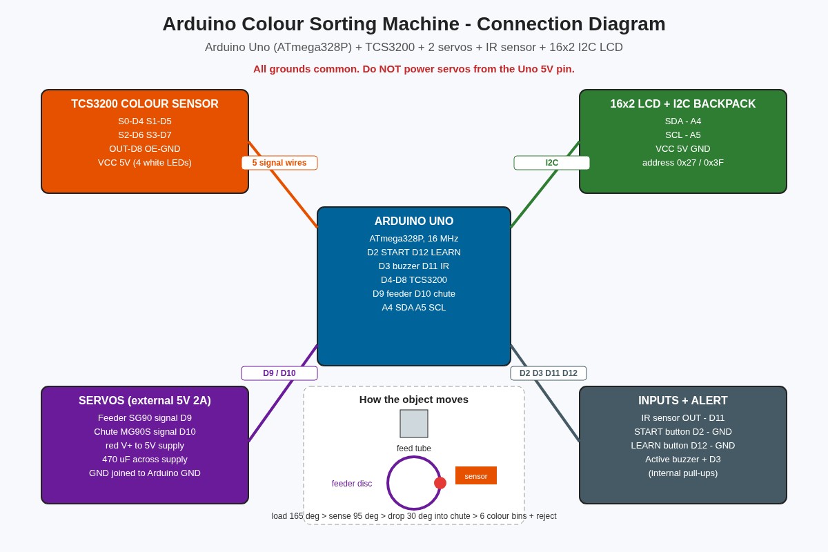
Connection Diagram
The diagram above shows how the modules connect to the Arduino and how an object moves through the machine. The drawing below lists every pin exactly as used in the code.
Building the Mechanism
- Feed tube: a 12–15 mm plastic tube or a rolled card tube, a little wider than your objects. Fix it vertically above the feeder disc.
- Feeder disc: a 50 mm round disc (MDF, acrylic or 3D print) with one hole slightly bigger than one object, screwed to the SG90 horn. Under the disc, a fixed base plate has no hole except at the drop position (30°), so the object rides in the hole until it reaches the chute.
- Sensor window: mount the TCS3200 looking down on the hole at 95°, 10–15 mm above it, inside a small black shroud so room light does not change the reading. Put the IR sensor at the side of the same position.
- Chute: a 120 mm half pipe (cut PVC pipe or folded card) glued to the MG90S horn. Arrange 7 cups in a half circle under the end of the chute.
- Tune the angles: adjust
FEED_LOAD,FEED_SENSE,FEED_DROPandCHUTE_ANGLE[]at the top of the sketch to match your build.
Code
Install LiquidCrystal I2C (by Frank de Brabander) from the Library Manager. Servo, Wire and EEPROM come with the Arduino IDE. Select Arduino Uno (or Nano, ATmega328P) and upload. The sketch was compile-checked for the Uno: about 11 KB of flash and 870 bytes of RAM.
/*
  Arduino Colour Sorting Machine
  TCS3200 colour sensor + 2 servos + 16x2 I2C LCD + IR presence sensor + buzzer
  Board: Arduino Uno / Nano (ATmega328P, 16 MHz)
  Arduino Project Hub - ardiunoprojecthub.online - Project #68

  How it works:
   1. The feeder servo picks one object (bead, candy, small block) from the tube
      and carries it under the TCS3200 colour sensor.
   2. The sensor measures red, green, blue and clear light. The sketch compares
      the reading with six learned reference colours (nearest match).
   3. The chute servo turns to the bin for that colour, the feeder drops the
      object, and the LCD shows the colour and the count for each bin.
   4. Counts and learned colours are kept in EEPROM, so they survive power-off.

  Buttons (to GND, internal pull-ups):
   START (D2)  : short press = run / pause, long press (2 s) = reset counters
   LEARN (D12) : hold while powering up = learn mode (teach the 6 colours)
*/

#include <Wire.h>
#include <Servo.h>
#include <EEPROM.h>
#include <LiquidCrystal_I2C.h>

// ---------------- Pin map ----------------
const uint8_t PIN_START  = 2;   // start / pause button
const uint8_t PIN_BUZZER = 3;   // active buzzer (+)
const uint8_t PIN_S0     = 4;   // TCS3200 frequency scaling
const uint8_t PIN_S1     = 5;
const uint8_t PIN_S2     = 6;   // TCS3200 photodiode filter select
const uint8_t PIN_S3     = 7;
const uint8_t PIN_OUT    = 8;   // TCS3200 square-wave output
const uint8_t PIN_FEED   = 9;   // feeder (top) servo signal
const uint8_t PIN_CHUTE  = 10;  // chute (bottom) servo signal
const uint8_t PIN_IR     = 11;  // IR obstacle sensor OUT (LOW = object present)
const uint8_t PIN_LEARN  = 12;  // learn button
const uint8_t PIN_LED    = 13;  // status LED (on-board)

// ---------------- Mechanics (tune for your build) ----------------
const uint8_t FEED_LOAD   = 165;  // feeder hole under the tube
const uint8_t FEED_SENSE  = 95;   // feeder hole under the colour sensor
const uint8_t FEED_DROP   = 30;   // feeder hole over the chute
const uint8_t CHUTE_ANGLE[7] = {20, 45, 70, 95, 120, 145, 170}; // 6 colours + reject bin

// ---------------- Colour table ----------------
const uint8_t NUM_COLOURS = 6;
const char* const COLOUR_NAME[7] = {"Red", "Orange", "Yellow", "Green", "Blue", "Brown", "Reject"};
const uint8_t REJECT = 6;
const uint16_t MATCH_LIMIT = 60;   // larger distance than this = unknown colour

struct Rgb { uint16_t r, g, b; };  // normalised values 0..255 (higher = more of that colour)

// Typical defaults for a TCS3200 at 20% scaling, ~15 mm above the object.
// Run learn mode once for best results with your own lighting and objects.
Rgb ref[NUM_COLOURS] = {
  {190,  60,  70}, {200, 110,  60}, {200, 185,  80},
  { 80, 170,  90}, { 60, 110, 200}, {120,  90,  80}
};

uint16_t binCount[7] = {0};

// ---------------- EEPROM layout ----------------
const uint16_t EE_MAGIC_ADDR = 0;     // 2 bytes
const uint16_t EE_REF_ADDR   = 2;     // 6 x 6 bytes
const uint16_t EE_COUNT_ADDR = 40;    // 7 x 2 bytes
const uint16_t EE_MAGIC      = 0xC068;

LiquidCrystal_I2C lcd(0x27, 16, 2);   // change to 0x3F if your LCD stays blank
Servo feeder, chute;

bool running = false;
uint16_t whiteRef[3] = {0, 0, 0};     // period (us) under white card, for normalising
uint16_t blackRef[3] = {0, 0, 0};     // period (us) under black card

// ---------------- Helpers ----------------
void beep(uint16_t ms) {
  digitalWrite(PIN_BUZZER, HIGH);
  delay(ms);
  digitalWrite(PIN_BUZZER, LOW);
}

void lcdLine(uint8_t row, const char* text) {
  lcd.setCursor(0, row);
  uint8_t n = 0;
  while (text[n] && n < 16) { lcd.write(text[n]); n++; }
  while (n < 16) { lcd.write(' '); n++; }    // clear the rest of the row
}

// Wait for a button press and its release (with debounce). Returns press time in ms.
uint32_t waitPress(uint8_t pin) {
  while (digitalRead(pin) == HIGH) {}
  delay(25);
  uint32_t t0 = millis();
  while (digitalRead(pin) == LOW) {}
  delay(25);
  return millis() - t0;
}

// Move a servo slowly so the object does not jump out of the feeder hole.
void moveSlow(Servo &s, uint8_t target) {
  int pos = s.read();
  int step = (target > pos) ? 1 : -1;
  while (pos != target) {
    pos += step;
    s.write(pos);
    delay(6);
  }
}

// Read one filter channel: average period of the OUT square wave in microseconds.
// Lower period = more light of that colour.
uint16_t readPeriod(bool s2, bool s3) {
  digitalWrite(PIN_S2, s2);
  digitalWrite(PIN_S3, s3);
  delay(5);                                  // let the filter settle
  uint32_t sum = 0;
  uint8_t ok = 0;
  for (uint8_t i = 0; i < 8; i++) {
    uint32_t p = pulseIn(PIN_OUT, LOW, 20000UL);
    if (p > 0) { sum += p; ok++; }
  }
  if (ok == 0) return 0xFFFF;               // no signal: sensor not wired or too dark
  return (uint16_t)(sum / ok);
}

// Raw periods for red, green and blue filters
void readRaw(uint16_t raw[3]) {
  raw[0] = readPeriod(LOW, LOW);      // red filter
  raw[1] = readPeriod(HIGH, HIGH);    // green filter
  raw[2] = readPeriod(LOW, HIGH);     // blue filter
}

// Convert periods to 0..255 using the black and white calibration
Rgb readColour() {
  uint16_t raw[3];
  readRaw(raw);
  uint16_t v[3];
  for (uint8_t i = 0; i < 3; i++) {
    long x = map((long)raw[i], (long)blackRef[i], (long)whiteRef[i], 0L, 255L);
    v[i] = (uint16_t)constrain(x, 0L, 255L);
  }
  Rgb c = {v[0], v[1], v[2]};
  return c;
}

// Nearest reference colour (Manhattan distance). Returns REJECT if nothing is close.
uint8_t classify(const Rgb &c, uint16_t &bestDist) {
  uint8_t best = REJECT;
  bestDist = 0xFFFF;
  for (uint8_t i = 0; i < NUM_COLOURS; i++) {
    uint16_t d = abs((int)c.r - (int)ref[i].r) +
                 abs((int)c.g - (int)ref[i].g) +
                 abs((int)c.b - (int)ref[i].b);
    if (d < bestDist) { bestDist = d; best = i; }
  }
  if (bestDist > MATCH_LIMIT) best = REJECT;
  return best;
}

// ---------------- EEPROM ----------------
void saveCounts() {
  for (uint8_t i = 0; i < 7; i++) EEPROM.put(EE_COUNT_ADDR + i * 2, binCount[i]);
}

void saveRefs() {
  EEPROM.put(EE_MAGIC_ADDR, EE_MAGIC);
  for (uint8_t i = 0; i < NUM_COLOURS; i++) EEPROM.put(EE_REF_ADDR + i * 6, ref[i]);
  // black/white calibration stored after the colour table
  EEPROM.put(EE_REF_ADDR + 36 + 16, whiteRef);
  EEPROM.put(EE_REF_ADDR + 36 + 22, blackRef);
}

bool loadEeprom() {
  uint16_t magic;
  EEPROM.get(EE_MAGIC_ADDR, magic);
  if (magic != EE_MAGIC) return false;
  for (uint8_t i = 0; i < NUM_COLOURS; i++) EEPROM.get(EE_REF_ADDR + i * 6, ref[i]);
  for (uint8_t i = 0; i < 7; i++) {
    EEPROM.get(EE_COUNT_ADDR + i * 2, binCount[i]);
    if (binCount[i] == 0xFFFF) binCount[i] = 0;
  }
  EEPROM.get(EE_REF_ADDR + 36 + 16, whiteRef);
  EEPROM.get(EE_REF_ADDR + 36 + 22, blackRef);
  return true;
}

// ---------------- Learn mode ----------------
// Step 1: white card, step 2: black card, steps 3..8: one sample of each colour.
void learnMode() {
  char buf[17];
  moveSlow(feeder, FEED_SENSE);

  lcdLine(0, "LEARN: put WHITE");
  lcdLine(1, "card, press LRN");
  waitPress(PIN_LEARN);
  readRaw(whiteRef);
  beep(60);

  lcdLine(0, "LEARN: put BLACK");
  lcdLine(1, "card, press LRN");
  waitPress(PIN_LEARN);
  readRaw(blackRef);
  beep(60);

  for (uint8_t i = 0; i < NUM_COLOURS; i++) {
    snprintf(buf, sizeof(buf), "LEARN: %s", COLOUR_NAME[i]);
    lcdLine(0, buf);
    lcdLine(1, "place, press LRN");
    waitPress(PIN_LEARN);
    // average three readings for a stable reference
    uint32_t r = 0, g = 0, b = 0;
    for (uint8_t k = 0; k < 3; k++) {
      Rgb c = readColour();
      r += c.r; g += c.g; b += c.b;
    }
    ref[i].r = r / 3; ref[i].g = g / 3; ref[i].b = b / 3;
    snprintf(buf, sizeof(buf), "R%3u G%3u B%3u", ref[i].r, ref[i].g, ref[i].b);
    lcdLine(1, buf);
    beep(60);
    delay(800);
  }
  saveRefs();
  lcdLine(0, "Colours saved!");
  lcdLine(1, "Press START");
  beep(200);
}

// ---------------- Display ----------------
void showIdle() {
  char buf[17];
  uint16_t total = 0;
  for (uint8_t i = 0; i < 7; i++) total += binCount[i];
  lcdLine(0, running ? "RUNNING" : "PAUSED - START");
  snprintf(buf, sizeof(buf), "Total sorted %u", total);
  lcdLine(1, buf);
}

// ---------------- Sort one object ----------------
void sortOne() {
  char buf[17];

  // 1. pick up an object from the tube
  moveSlow(feeder, FEED_LOAD);
  delay(400);

  // 2. carry it under the sensor
  moveSlow(feeder, FEED_SENSE);
  delay(300);

  // 3. is there really an object? (IR sensor looks into the feeder hole)
  if (digitalRead(PIN_IR) == HIGH) {
    lcdLine(0, "Tube empty?");
    lcdLine(1, "Refill & START");
    beep(400);
    running = false;
    return;
  }

  // 4. read and classify the colour
  Rgb c = readColour();
  uint16_t dist;
  uint8_t bin = classify(c, dist);

  snprintf(buf, sizeof(buf), "%-7s d=%u", COLOUR_NAME[bin], dist);
  lcdLine(0, buf);
  snprintf(buf, sizeof(buf), "R%3u G%3u B%3u", c.r, c.g, c.b);
  lcdLine(1, buf);

  Serial.print(F("RGB "));
  Serial.print(c.r); Serial.print(' ');
  Serial.print(c.g); Serial.print(' ');
  Serial.print(c.b);
  Serial.print(F(" -> "));
  Serial.println(COLOUR_NAME[bin]);

  // 5. turn the chute, then drop the object
  moveSlow(chute, CHUTE_ANGLE[bin]);
  delay(150);
  moveSlow(feeder, FEED_DROP);
  delay(350);

  binCount[bin]++;
  saveCounts();                // EEPROM.put only writes bytes that changed
  if (bin == REJECT) beep(150);

  snprintf(buf, sizeof(buf), "%s bin: %u", COLOUR_NAME[bin], binCount[bin]);
  lcdLine(1, buf);
}

// ---------------- Setup / loop ----------------
void setup() {
  Serial.begin(9600);
  pinMode(PIN_START, INPUT_PULLUP);
  pinMode(PIN_LEARN, INPUT_PULLUP);
  pinMode(PIN_IR, INPUT);
  pinMode(PIN_BUZZER, OUTPUT);
  pinMode(PIN_LED, OUTPUT);
  pinMode(PIN_S0, OUTPUT); pinMode(PIN_S1, OUTPUT);
  pinMode(PIN_S2, OUTPUT); pinMode(PIN_S3, OUTPUT);
  pinMode(PIN_OUT, INPUT);
  digitalWrite(PIN_S0, HIGH);  // 20% output frequency scaling (S0=H, S1=L)
  digitalWrite(PIN_S1, LOW);

  lcd.init();
  lcd.backlight();

  feeder.attach(PIN_FEED);
  chute.attach(PIN_CHUTE);
  feeder.write(FEED_SENSE);
  chute.write(CHUTE_ANGLE[3]);

  bool haveData = loadEeprom();
  if (!haveData) {
    // first power-up: sensible default periods (white ~ 40 us, black ~ 400 us)
    for (uint8_t i = 0; i < 3; i++) { whiteRef[i] = 40; blackRef[i] = 400; }
    for (uint8_t i = 0; i < 7; i++) binCount[i] = 0;
    saveRefs();            // write defaults so counts are kept from now on
    saveCounts();
  }

  lcdLine(0, "Colour Sorter");
  lcdLine(1, haveData ? "Data loaded" : "Defaults - LEARN");
  beep(80);
  delay(1200);

  if (digitalRead(PIN_LEARN) == LOW) {   // LEARN held at power-up
    while (digitalRead(PIN_LEARN) == LOW) {}
    delay(50);
    learnMode();
  }
  showIdle();
}

void loop() {
  // START button: short press toggles run/pause, long press resets the counters
  if (digitalRead(PIN_START) == LOW) {
    uint32_t held = waitPress(PIN_START);
    if (held > 2000) {
      for (uint8_t i = 0; i < 7; i++) binCount[i] = 0;
      saveCounts();
      running = false;
      lcdLine(0, "Counters reset");
      beep(300);
      delay(1000);
    } else {
      running = !running;
      beep(40);
    }
    showIdle();
  }

  digitalWrite(PIN_LED, running);
  if (running) {
    sortOne();
    if (!running) showIdle();
  }
}
Calibration and Testing
- Learn mode: hold the LEARN button while you power up (or press reset), then release it. The LCD asks for a white card, then a black card, then one sample of each of the six colours. Place each one in the feeder hole under the sensor and press LEARN. The values are saved in EEPROM.
- Check readings: open the Serial Monitor at 9600 baud. Each sorted object prints a line like
RGB 192 64 71 -> Red. If two colours give very similar numbers (for example orange and brown), run learn mode again with better shading. - Run: press START to begin. The LED on D13 lights and the machine sorts about one object every 2–3 seconds. Press START again to pause; hold it for 2 seconds to reset the counters.
- Tune the reject limit: raise
MATCH_LIMITif too many good objects go to reject, lower it if wrong colours slip into a bin.
Troubleshooting
| Problem | Fix |
|---|---|
| LCD backlight is on but no text | Turn the blue contrast pot on the I2C backpack. If still blank, change the address in the sketch from 0x27 to 0x3F. |
| Arduino resets when the servos move | The servos are drawing current from the Uno. Power them from a separate 5 V 2 A supply, join the grounds and add the 470 µF capacitor. |
| All readings are 0 or 255 | OUT is not reaching D8 or OE is not tied to GND. Check S0 to S3 wiring and that the four white LEDs on the module are lit. |
| Colour changes with room light | Shade the sensor with a black tube or box and run learn mode again in the same lighting. |
| Every object goes to reject | Learn mode was skipped and the defaults do not match your objects. Hold LEARN at power-up and teach all six colours. |
| Machine says Tube empty? with objects present | Adjust the IR sensor’s blue trim pot until its LED turns on only when an object is in the hole. Matt black objects may need the sensor moved closer. |
| Objects jam between disc and base | Make the hole 1–2 mm bigger than the object and sand the edges. The slow servo movement in the code also helps. |
| Chute misses the cups | Change the values in CHUTE_ANGLE[] in 5° steps until each object lands in the middle of its cup. |
Ideas to Extend
- Add an HC-05 Bluetooth module to send the counts to a phone.
- Replace the SG90 feeder with a small stepper motor for faster, more precise feeding.
- Add a seventh learned colour (purple or white) by using the reject position as a real bin.