
Build a Wemos D1 Mini Wi-Fi doorbell that rings a buzzer and sends a push notification to your phone through ntfy.sh. Wiring table, diagram and full code.
Need it ready-made? Buy Ready Project
This Wemos D1 Mini Wi-Fi doorbell turns a simple push button into a smart doorbell. When a visitor presses the button, a buzzer rings at the door and your phone gets a push notification within a second or two, even if you are upstairs or away from home.
The alert is sent through ntfy.sh, a free push notification service that needs no account, no API key and no app server of your own. You just install the free ntfy app on Android or iPhone and subscribe to a topic name that you choose.
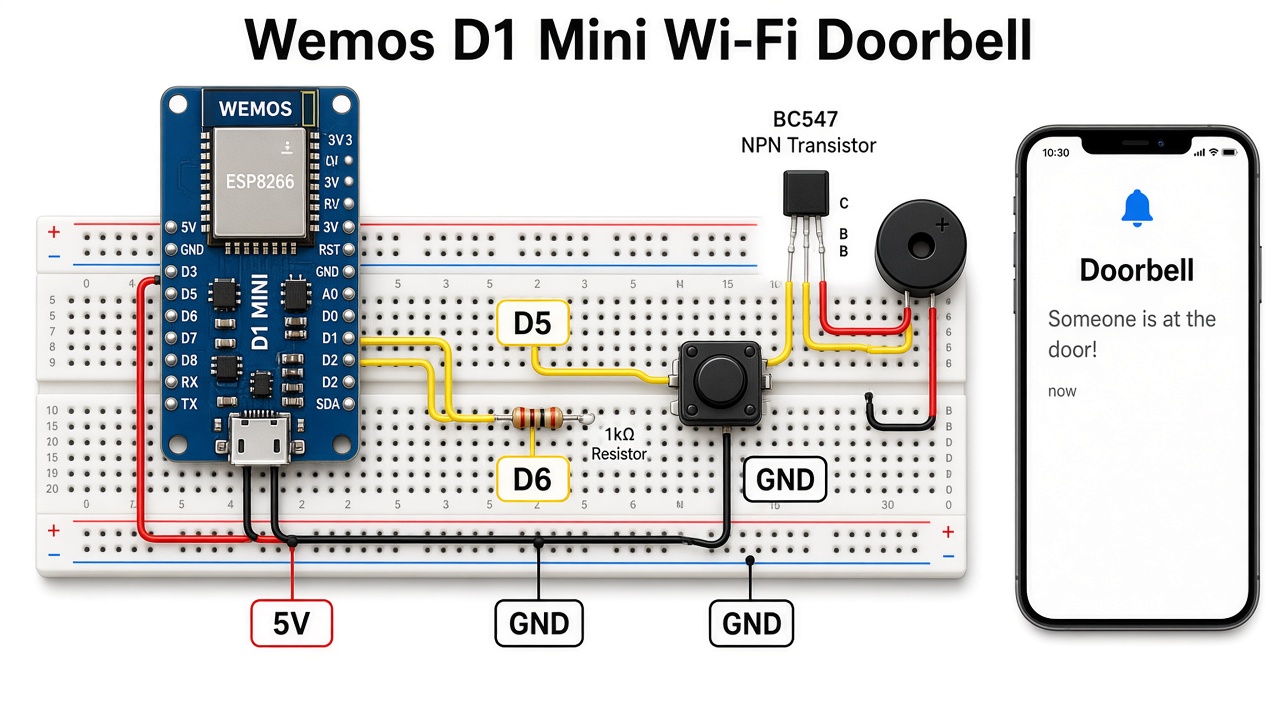
How It Works
- Button: the doorbell button connects D5 to GND. The ESP8266 internal pull-up keeps D5 HIGH, so a press reads as LOW. The code debounces the press for 50 ms so one press counts once.
- Buzzer: the D1 Mini pin can only supply a few milliamps, so it switches a BC547 transistor through a 1 kΩ resistor. The transistor connects the 5 V active buzzer to ground and it plays a short ding-dong.
- Wi-Fi alert: right after the ring, the board sends an HTTPS POST to
https://ntfy.sh/your-topicwith a title, a high priority and a bell icon. The ntfy app on your phone shows it as a normal notification. - Cooldown: if someone presses the button again and again, the buzzer still rings but only one phone alert is sent every 10 seconds, so your phone is not flooded.
- Status LED: the built-in LED blinks while Wi-Fi connects and lights while an alert is being sent. The board reconnects to Wi-Fi by itself if the router restarts.
Components Required
- Wemos D1 Mini (ESP8266) – 1
- Push button (doorbell switch or 12 mm tactile button) – 1
- 5 V active buzzer – 1
- BC547 NPN transistor – 1
- 1 kΩ resistor – 1
- 5 V USB power adapter with micro-USB cable
- Breadboard or small perfboard, jumper wires
- Two-core wire to run the button to the door (optional)
Wiring Table
| From | To | Notes |
|---|---|---|
| Button leg 1 | D1 Mini D5 (GPIO14) | Internal pull-up used, no resistor needed |
| Button leg 2 | D1 Mini GND | |
| D1 Mini D6 (GPIO12) | 1 kΩ resistor, then BC547 base | Switches the transistor |
| BC547 emitter | D1 Mini GND | |
| BC547 collector | Buzzer – (short leg) | Low side switch |
| Buzzer + (long leg) | D1 Mini 5V pin | 5 V from USB |
| D1 Mini micro-USB | 5 V adapter | Powers the whole circuit |
| D4 (GPIO2) | Built-in LED | Status light, no wiring needed |
Connection Diagram
The illustration above shows the general breadboard layout. The pin-accurate drawing below matches the wiring table exactly, so follow it when you build the circuit.
Setting Up the Phone Alerts
- Install the free ntfy app from the Play Store or App Store.
- Tap the + button and subscribe to a topic name, for example
raj-home-doorbell-7k29. Use a long, hard-to-guess name, because anyone who knows the topic can read it. - Put the same topic name in
NTFY_TOPICin the code below.
Code
Install the ESP8266 board package in the Arduino IDE (Boards Manager, search “esp8266”), choose LOLIN(WEMOS) D1 R2 & mini as the board, replace the Wi-Fi and topic placeholders, and upload. No extra libraries are needed.
/*
  Wemos D1 Mini Wi-Fi Doorbell with ntfy Phone Alerts
  ---------------------------------------------------
  - Press the doorbell button: the buzzer rings and a push
    notification is sent to your phone through ntfy.sh.
  - Install the free "ntfy" app on your phone and subscribe
    to the same topic name you set below.

  Wiring (see the wiring table in the post):
    Push button : D5 (GPIO14) to GND  (internal pull-up used)
    Buzzer      : D6 (GPIO12) -> 1k -> BC547 base, buzzer on collector
    Status LED  : built-in LED on D4 (GPIO2, active LOW)
*/

#include <ESP8266WiFi.h>
#include <ESP8266HTTPClient.h>
#include <WiFiClientSecure.h>

// ---------- User settings (replace the placeholders) ----------
const char* WIFI_SSID     = "YOUR_WIFI_SSID";
const char* WIFI_PASSWORD = "YOUR_WIFI_PASSWORD";
// Pick a long, hard-to-guess topic name. Anyone who knows it can read it.
const char* NTFY_TOPIC    = "YOUR_UNIQUE_DOORBELL_TOPIC";
// ---------------------------------------------------------------

const uint8_t BUTTON_PIN = D5;   // GPIO14
const uint8_t BUZZER_PIN = D6;   // GPIO12 (drives BC547)
const uint8_t LED_PIN    = LED_BUILTIN; // GPIO2, LOW = ON

const unsigned long DEBOUNCE_MS = 50;     // ignore contact bounce
const unsigned long COOLDOWN_MS = 10000;  // max one alert every 10 s

unsigned long lastAlert = 0;
bool lastReading = HIGH;
bool stableState = HIGH;
unsigned long lastChange = 0;

// Ring the buzzer in a simple "ding-dong" pattern
void ringBuzzer() {
  for (int i = 0; i < 2; i++) {
    digitalWrite(BUZZER_PIN, HIGH);
    delay(300);
    digitalWrite(BUZZER_PIN, LOW);
    delay(150);
  }
}

// Connect (or reconnect) to Wi-Fi, blinking the LED while waiting
void connectWiFi() {
  if (WiFi.status() == WL_CONNECTED) return;
  Serial.print("Connecting to Wi-Fi");
  WiFi.mode(WIFI_STA);
  WiFi.begin(WIFI_SSID, WIFI_PASSWORD);
  unsigned long start = millis();
  while (WiFi.status() != WL_CONNECTED && millis() - start < 20000) {
    digitalWrite(LED_PIN, !digitalRead(LED_PIN));
    delay(250);
    Serial.print(".");
  }
  digitalWrite(LED_PIN, HIGH); // LED off
  Serial.println(WiFi.status() == WL_CONNECTED ? " connected" : " failed");
}

// Send a push notification through ntfy.sh (HTTPS POST)
bool sendNotification() {
  connectWiFi();
  if (WiFi.status() != WL_CONNECTED) return false;

  WiFiClientSecure client;
  client.setInsecure();          // skip certificate check (simple setup)
  HTTPClient http;
  String url = String("https://ntfy.sh/") + NTFY_TOPIC;
  if (!http.begin(client, url)) return false;

  http.addHeader("Title", "Doorbell");
  http.addHeader("Priority", "high");
  http.addHeader("Tags", "bell");
  int code = http.POST("Someone is at the door!");
  http.end();

  Serial.printf("ntfy response: %d\n", code);
  return code == 200;
}

void setup() {
  Serial.begin(115200);
  pinMode(BUTTON_PIN, INPUT_PULLUP);
  pinMode(BUZZER_PIN, OUTPUT);
  pinMode(LED_PIN, OUTPUT);
  digitalWrite(BUZZER_PIN, LOW);
  digitalWrite(LED_PIN, HIGH);
  connectWiFi();
}

void loop() {
  // --- Debounce the button ---
  bool reading = digitalRead(BUTTON_PIN);
  if (reading != lastReading) {
    lastChange = millis();
    lastReading = reading;
  }
  if (millis() - lastChange > DEBOUNCE_MS && reading != stableState) {
    stableState = reading;

    // Button pressed (pin pulled LOW)
    if (stableState == LOW) {
      ringBuzzer();
      if (millis() - lastAlert > COOLDOWN_MS || lastAlert == 0) {
        lastAlert = millis();
        digitalWrite(LED_PIN, LOW);           // LED on while sending
        bool ok = sendNotification();
        digitalWrite(LED_PIN, HIGH);
        Serial.println(ok ? "Alert sent" : "Alert failed");
      }
    }
  }

  // Keep Wi-Fi alive in the background
  if (WiFi.status() != WL_CONNECTED) connectWiFi();
}
Testing
- Open the Serial Monitor at 115200 baud and check that it prints “connected”.
- Press the button. The buzzer should play two beeps and the monitor should show “ntfy response: 200” and “Alert sent”.
- Your phone should show a Doorbell notification saying “Someone is at the door!”
- Press again within 10 seconds: the buzzer rings but no second alert is sent.
Troubleshooting
| Problem | Fix |
|---|---|
| No notification on the phone | Check that the topic in the app and in the code match exactly, and that the phone has internet. |
| ntfy response is -1 | The board could not reach ntfy.sh. Check the Wi-Fi name and password and that the router has internet. |
| Buzzer does not sound | Check the transistor pins (E, B, C) and use an active buzzer, not a passive one. |
| One press gives two alerts | Increase DEBOUNCE_MS to 100 or use a better quality button. |
Ideas to Extend
- Add an ESP32-CAM so the alert includes a photo of the visitor.
- Run the board on an 18650 cell with deep sleep so it works without a wall adapter.
- Send the alert to a self-hosted ntfy server on your own network for full privacy.