
Build a Wemos D1 Mini Wi-Fi RGB LED strip controller with IRLZ44N MOSFETs, a web colour picker, brightness slider, rainbow mode and a push button. Wiring table, diagram and full code.
Need it ready-made? Buy Ready Project
This Wemos D1 Mini RGB LED strip controller lets you set any colour and brightness on an ordinary 12V RGB (5050) LED strip from your phone’s browser. No app is needed: the ESP8266 hosts a small web page with a colour picker, a brightness slider, ON/OFF buttons and a smooth rainbow mode. A push button on the board switches the strip on and off without a phone, and the last setting is remembered after a power cut.
It is a practical medium-level IoT project for room backlighting, a TV bias light, a desk or a shop display, and a good way to learn PWM dimming with logic-level MOSFETs.
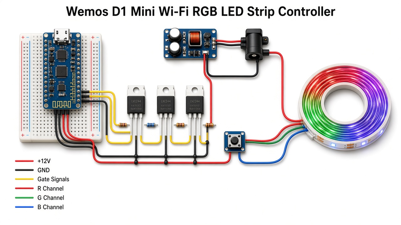
How It Works
- The strip: a common-anode 12V RGB strip has four wires: +12V and one return wire each for red, green and blue. A colour lights up when its return wire is pulled to ground.
- MOSFET switches: three IRLZ44N logic-level MOSFETs act as low-side switches. Each gate is driven straight from a 3.3V D1 Mini pin through a 100 Ω resistor, and a 10k pull-down keeps the strip off while the board boots.
- PWM dimming: the ESP8266 drives D5, D6 and D7 with 1 kHz, 10-bit PWM. The code applies a simple gamma curve so low brightness levels look smooth to the eye.
- Web control: the board joins your Wi-Fi and serves a page at its IP address. Moving the colour picker or slider sends a short request such as
/set?hex=ff7828and the colour changes instantly. - Rainbow mode: the code steps through all 360 hues every 30 ms for a slow, continuous colour fade.
- Memory and button: colour, brightness, power and mode are stored in EEPROM 3 seconds after the last change, so a slider drag does not wear the flash. The D2 button toggles the strip with a 50 ms debounce.
- Power: one 12V adapter feeds the strip directly and an LM2596 buck converter makes 5V for the D1 Mini.
Components Required
- Wemos D1 Mini (ESP8266) – 1
- 12V RGB 5050 LED strip, common anode, up to 5 m – 1
- IRLZ44N logic-level N-channel MOSFET – 3
- Resistors: 100 Ω – 3, 10k – 3
- LM2596 buck converter module (set to 5V) – 1
- 12V DC adapter, 2A for 2 m or 5A for 5 m of strip – 1
- DC barrel jack – 1
- Tactile push button – 1
- 470 µF 25V electrolytic capacitor – 1
- Breadboard or perfboard, screw terminals and jumper wires
Wiring Table
| From | To | Notes |
|---|---|---|
| 12V adapter (+) | Strip +12V wire and LM2596 IN+ | |
| 12V adapter (-) | LM2596 IN-, MOSFET sources, D1 Mini G | One common ground |
| LM2596 OUT+ | D1 Mini 5V | Adjust to 5.0V before connecting |
| LM2596 OUT- | D1 Mini G | |
| D1 Mini D5 (GPIO14) | IRLZ44N #1 gate via 100 Ω | 10k from gate to GND |
| IRLZ44N #1 drain | Strip R wire | Source to GND |
| D1 Mini D6 (GPIO12) | IRLZ44N #2 gate via 100 Ω | 10k from gate to GND |
| IRLZ44N #2 drain | Strip G wire | Source to GND |
| D1 Mini D7 (GPIO13) | IRLZ44N #3 gate via 100 Ω | 10k from gate to GND |
| IRLZ44N #3 drain | Strip B wire | Source to GND |
| Push button | D2 (GPIO4) and GND | Uses the internal pull-up |
| 470 µF capacitor | +12V and GND at the strip | Observe polarity |
IRLZ44N pins, with the printed face toward you and legs down: gate, drain, source (left to right).
Connection Diagram
The illustration above shows a typical layout; its wire routes are only for orientation. The pin-accurate drawing below matches the wiring table exactly, so follow it while building.
Code
Install the ESP8266 board package in the Arduino IDE (Boards Manager, search “esp8266”), choose LOLIN(WEMOS) D1 R2 & mini, put your Wi-Fi name and password in place of the placeholders, and upload. No extra libraries are needed. Open the Serial Monitor at 115200 baud to see the board’s IP address, then open that address in your phone’s browser.
/*
  Wemos D1 Mini Wi-Fi RGB LED Strip Controller
  - 12V common-anode RGB (5050) strip driven by 3x IRLZ44N logic-level MOSFETs
  - Web page with colour picker, brightness slider, ON/OFF and Rainbow mode
  - Push button on D2 toggles the strip ON/OFF without a phone
  - Last colour, brightness and mode are saved in EEPROM
  Board: LOLIN(WEMOS) D1 R2 & mini (ESP8266 core). No extra libraries needed.
*/
#include <ESP8266WiFi.h>
#include <ESP8266WebServer.h>
#include <EEPROM.h>

const char* WIFI_SSID = "YOUR_WIFI_SSID";       // <-- your Wi-Fi name
const char* WIFI_PASS = "YOUR_WIFI_PASSWORD";   // <-- your Wi-Fi password

// MOSFET gate pins (each through a 100 ohm resistor, 10k pull-down to GND)
const uint8_t PIN_R = D5;   // GPIO14
const uint8_t PIN_G = D6;   // GPIO12
const uint8_t PIN_B = D7;   // GPIO13
const uint8_t PIN_BTN = D2; // GPIO4, push button to GND

ESP8266WebServer server(80);

// Current settings
uint8_t red = 255, green = 120, blue = 40;  // warm white default
uint8_t brightness = 80;                    // 0-100 %
bool powerOn = true;
bool rainbow = false;

uint16_t hue = 0;                 // used by rainbow mode (0-359)
unsigned long lastStep = 0;
unsigned long lastSaveRequest = 0;
bool savePending = false;

// ---------- EEPROM storage ----------
const uint8_t MAGIC = 0x37;
void saveSettings() {
  EEPROM.write(0, MAGIC);
  EEPROM.write(1, red);
  EEPROM.write(2, green);
  EEPROM.write(3, blue);
  EEPROM.write(4, brightness);
  EEPROM.write(5, powerOn);
  EEPROM.write(6, rainbow);
  EEPROM.commit();
}
void loadSettings() {
  if (EEPROM.read(0) != MAGIC) return;   // first boot: keep defaults
  red = EEPROM.read(1);
  green = EEPROM.read(2);
  blue = EEPROM.read(3);
  brightness = constrain(EEPROM.read(4), 0, 100);
  powerOn = EEPROM.read(5);
  rainbow = EEPROM.read(6);
}
// Delay EEPROM writes so dragging a slider doesn't wear the flash
void requestSave() { savePending = true; lastSaveRequest = millis(); }

// ---------- Output ----------
// Simple gamma correction so low brightness looks smooth
uint16_t gamma10(uint8_t v) {
  float f = v / 255.0;
  return (uint16_t)(f * f * 1023.0 + 0.5);
}
void writeRGB(uint8_t r, uint8_t g, uint8_t b) {
  if (!powerOn) { r = g = b = 0; }
  uint16_t scale = brightness;   // 0-100
  analogWrite(PIN_R, gamma10(r) * scale / 100);
  analogWrite(PIN_G, gamma10(g) * scale / 100);
  analogWrite(PIN_B, gamma10(b) * scale / 100);
}
// Convert hue (0-359) at full saturation to RGB
void hueToRGB(uint16_t h, uint8_t &r, uint8_t &g, uint8_t &b) {
  uint8_t region = h / 60;
  uint8_t rem = (h % 60) * 255 / 60;
  switch (region) {
    case 0: r = 255; g = rem; b = 0; break;
    case 1: r = 255 - rem; g = 255; b = 0; break;
    case 2: r = 0; g = 255; b = rem; break;
    case 3: r = 0; g = 255 - rem; b = 255; break;
    case 4: r = rem; g = 0; b = 255; break;
    default: r = 255; g = 0; b = 255 - rem; break;
  }
}
void applyOutput() {
  if (rainbow) return;   // rainbow updates itself in loop()
  writeRGB(red, green, blue);
}

// ---------- Web page ----------
const char PAGE[] PROGMEM = R"HTML(
<!DOCTYPE html><html><head><meta name="viewport" content="width=device-width,initial-scale=1">
<title>RGB Strip</title>
<style>body{font-family:Arial;text-align:center;background:#111;color:#eee;margin:0;padding:20px}
input[type=color]{width:160px;height:160px;border:none;background:none}
input[type=range]{width:80%}button{font-size:18px;margin:8px;padding:12px 22px;border:0;border-radius:8px}
#on{background:#2e7d32;color:#fff}#off{background:#c62828;color:#fff}#rb{background:#6a1b9a;color:#fff}</style></head>
<body><h2>Wi-Fi RGB Strip</h2>
<input type="color" id="c" value="#ff7828"><br>
<p>Brightness: <span id="bv">80</span>%</p><input type="range" id="br" min="0" max="100" value="80"><br>
<button id="on">ON</button><button id="off">OFF</button><button id="rb">Rainbow</button>
<p id="st"></p>
<script>
function send(q){fetch('/set?'+q).then(r=>r.json()).then(show);}
function show(s){document.getElementById('st').innerText=(s.power?'ON':'OFF')+(s.rainbow?' - Rainbow':'');
 document.getElementById('br').value=s.bright;document.getElementById('bv').innerText=s.bright;
 if(!s.rainbow)document.getElementById('c').value=s.hex;}
c.oninput=e=>send('hex='+e.target.value.substring(1));
br.oninput=e=>{bv.innerText=e.target.value;send('bright='+e.target.value);};
on.onclick=()=>send('power=1');off.onclick=()=>send('power=0');rb.onclick=()=>send('rainbow=1');
fetch('/state').then(r=>r.json()).then(show);
</script></body></html>
)HTML";

String stateJSON() {
  char hex[8];
  snprintf(hex, sizeof(hex), "#%02x%02x%02x", red, green, blue);
  String s = "{\"power\":"; s += powerOn ? 1 : 0;
  s += ",\"rainbow\":"; s += rainbow ? 1 : 0;
  s += ",\"bright\":"; s += brightness;
  s += ",\"hex\":\""; s += hex; s += "\"}";
  return s;
}

void handleRoot() { server.send_P(200, "text/html", PAGE); }
void handleState() { server.send(200, "application/json", stateJSON()); }
void handleSet() {
  if (server.hasArg("hex")) {               // e.g. hex=ff7828
    long v = strtol(server.arg("hex").c_str(), NULL, 16);
    red = (v >> 16) & 0xFF; green = (v >> 8) & 0xFF; blue = v & 0xFF;
    rainbow = false; powerOn = true;
  }
  if (server.hasArg("bright")) brightness = constrain(server.arg("bright").toInt(), 0, 100);
  if (server.hasArg("power")) powerOn = server.arg("power").toInt() == 1;
  if (server.hasArg("rainbow")) { rainbow = server.arg("rainbow").toInt() == 1; powerOn = true; }
  applyOutput();
  requestSave();
  server.send(200, "application/json", stateJSON());
}

// ---------- Button ----------
bool lastBtn = HIGH;
unsigned long lastBtnChange = 0;
void checkButton() {
  bool b = digitalRead(PIN_BTN);
  if (b != lastBtn && millis() - lastBtnChange > 50) {   // 50 ms debounce
    lastBtnChange = millis();
    lastBtn = b;
    if (b == LOW) {            // pressed
      powerOn = !powerOn;
      applyOutput();
      if (!powerOn) writeRGB(0, 0, 0);
      requestSave();
    }
  }
}

void setup() {
  Serial.begin(115200);
  pinMode(PIN_R, OUTPUT); pinMode(PIN_G, OUTPUT); pinMode(PIN_B, OUTPUT);
  pinMode(PIN_BTN, INPUT_PULLUP);
  analogWriteRange(1023);     // 10-bit PWM
  analogWriteFreq(1000);      // 1 kHz, flicker-free for LED strips
  EEPROM.begin(16);
  loadSettings();
  applyOutput();

  WiFi.mode(WIFI_STA);
  WiFi.hostname("rgb-strip");
  WiFi.begin(WIFI_SSID, WIFI_PASS);
  Serial.print("Connecting");
  unsigned long t0 = millis();
  while (WiFi.status() != WL_CONNECTED && millis() - t0 < 20000) {
    delay(300); Serial.print(".");
    checkButton();            // button still works while connecting
  }
  Serial.println();
  if (WiFi.status() == WL_CONNECTED) {
    Serial.print("Open http://"); Serial.println(WiFi.localIP());
  } else {
    Serial.println("Wi-Fi failed - button control only");
  }

  server.on("/", handleRoot);
  server.on("/state", handleState);
  server.on("/set", handleSet);
  server.begin();
}

void loop() {
  server.handleClient();
  checkButton();

  // Rainbow mode: step the hue every 30 ms (full cycle in about 11 s)
  if (rainbow && powerOn && millis() - lastStep > 30) {
    lastStep = millis();
    uint8_t r, g, b;
    hueToRGB(hue, r, g, b);
    writeRGB(r, g, b);
    hue = (hue + 1) % 360;
  }

  // Save settings 3 s after the last change
  if (savePending && millis() - lastSaveRequest > 3000) {
    savePending = false;
    saveSettings();
  }
}
Troubleshooting
| Problem | Fix |
|---|---|
| Strip stays fully on | The MOSFET drain and source may be swapped, or the 10k pull-down is missing. Check the gate, drain, source order. |
| One colour never lights | Check that channel’s MOSFET and wire. Some strips mark the wires in the order +12V, G, R, B, so the colours may simply be swapped in the wiring. |
| Colours flicker on camera | Raise the PWM frequency with analogWriteFreq(2000) in setup(). |
| MOSFETs get hot | Use real IRLZ44N parts (not IRFZ44N, which needs 10V on the gate) and add a small heatsink for strips over 3 A. |
| Web page does not open | Make sure the phone is on the same Wi-Fi and use the IP address printed in the Serial Monitor. |
Ideas to Extend
- Add an IR receiver (TSOP1738) on D1 to use a cheap 44-key RGB remote as well.
- Add an LDR so the strip turns on automatically at dusk.
- Add MQTT so the strip works with Home Assistant.
2 thoughts on “Wemos D1 Mini Wi-Fi RGB LED Strip Controller with Web Colour Picker”