
Build an ATmega1284P smart egg incubator that holds 37.5 °C with PI-controlled 12 V PTC heating, keeps humidity with an ultrasonic mist module, turns the eggs with a servo every 3 hours, counts hatch days with a DS3231 RTC and protects the eggs with an independent DS18B20 over-temperature cut-off.
Need it ready-made? Buy Ready Project
Hatching eggs at home is mostly about patience and a very steady climate: the air must stay within a few tenths of a degree of 37.5 °C for three weeks, the humidity must follow the right schedule, and the eggs must be turned several times a day until the last three days. A simple thermostat with a bulb swings too much and does nothing about power cuts. This ATmega1284P smart egg incubator does the whole job automatically.
A DHT22 measures air temperature and humidity at egg level, and a PI (proportional-integral) controller drives a 12 V PTC heater through a MOSFET with time-proportional switching, so the temperature settles without big overshoots. An ultrasonic mist module keeps the humidity on target, a fan moves the air, and an MG996R servo tilts the egg tray every 3 hours. A DS3231 real-time clock counts the hatch day even after a power cut, and an independent DS18B20 probe switches the heater off if anything goes wrong. The ATmega1284P, with 128 KB flash and 16 KB RAM, has plenty of room for all of this plus an OLED menu and a CSV log, making it a solid big combination project.
How It Works
- Two temperature sensors: the DHT22 (PB0) is the main sensor for temperature and humidity. The DS18B20 probe (PB1) is a second, independent sensor. If the DHT22 fails five readings in a row, the controller automatically switches to the DS18B20 and shows DHT22 FAIL.
- PI heater control: every 2 seconds the code calculates the heater power: 25 % per °C of error plus a slowly growing integral term that removes the remaining offset. The integral only grows while the output is not saturated (anti-windup). The power is applied as on-time in a 10-second window on PD4, so 40 % means 4 s on and 6 s off.
- Humidity: the mist module on PD5 switches on when the humidity drops 3 % below the target and off when it reaches the target. The target follows the species preset: for chicken 50 % during days 1–18 and 65 % from day 19 (lockdown).
- Air circulation: the fan on PD6 runs at about 67 % PWM all the time to keep the temperature even, and goes to full speed if the air is 0.8 °C too warm or the safety cut-off is active.
- Egg turning: the servo on PD7 tilts the tray between 45° and 135° every 3 hours, moving 1° every 40 ms so the eggs are not jerked. In lockdown it parks the tray level (90°) and stops turning.
- Day counter: when you start a new hatch, the DS3231 time is saved in EEPROM. The current day is calculated from the RTC, so a power cut does not reset the count. Species, target temperature and humidity trim are stored in EEPROM too.
- Safety and alarms: if either sensor reads 39.5 °C or more, the heater is forced off and the buzzer beeps without mute. After a one-hour warm-up the buzzer also warns when the temperature is more than 1 °C off target, when a sensor is missing, or when the humidity falls below 35 % (water tray empty). A short press on SET mutes normal alarms for 30 minutes.
- Logging: every minute a CSV line (
time_s,day,air_C,rh,probe_C,heat_pct,mist,tilt) is sent at 9600 baud on TXD0, so you can plot the full incubation in a spreadsheet.
Components Required
- ATmega1284P microcontroller (40-pin DIP) – 1
- 16 MHz crystal + 2 × 22 pF capacitors – 1 set
- USBasp programmer (for burning the MightyCore bootloader / uploading) – 1
- DHT22 (AM2302) temperature and humidity sensor + 10 kΩ pull-up – 1
- DS18B20 waterproof temperature probe + 4.7 kΩ pull-up – 1
- DS3231 RTC module with CR2032 cell – 1
- 0.96″ SSD1306 I2C OLED 128×64 – 1
- 12 V 50 W PTC heater (or 12 V heating pad) – 1
- 5 V ultrasonic mist maker module with water tray – 1
- 12 V 80 mm DC fan – 1
- MG996R metal-gear servo + tilting egg tray – 1
- IRLZ44N logic-level MOSFETs with 220 Ω gate and 10 kΩ pull-down resistors – 3
- 1N4007 diode (fan flyback) – 1
- 12 V 10 A power supply + 10 A fuse holder – 1
- LM2596 buck converter set to 5 V (3 A) + 470 µF capacitor for the servo – 1
- 12 mm tactile push buttons (SET, UP, DOWN) – 3
- 5 V active buzzer + red LED with 330 Ω resistor – 1 each
- 100 nF decoupling capacitors (VCC, AVCC) + 10 kΩ RESET pull-up – 1 set
- Insulated box (thermocol / plywood) with a viewing window, perfboard and wires – 1
Wiring Table
| Part / pin | ATmega1284P pin (Arduino no.) | Notes |
|---|---|---|
| +5 V (from LM2596) | VCC (10), AVCC (30) | 100 nF from each to GND |
| GND | GND (11, 31) | Common with 12 V supply −, buck − and all MOSFET sources |
| 16 MHz crystal | XTAL2 (12), XTAL1 (13) | 22 pF from each crystal pin to GND |
| RESET | Pin 9 | 10 kΩ to +5 V (also to USBasp RESET) |
| DHT22 DATA | PB0 / D0 (1) | 10 kΩ pull-up to 5 V; sensor at egg height |
| DS18B20 DQ (yellow) | PB1 / D1 (2) | 4.7 kΩ pull-up to 5 V; red 5 V, black GND |
| SET / UP / DOWN buttons | PB2 / PB3 / PB4 = D2 / D3 / D4 (3, 4, 5) | Other leg to GND, internal pull-ups |
| OLED + DS3231 SCL | PC0 / D16 (22) | Both modules on the same I2C bus |
| OLED + DS3231 SDA | PC1 / D17 (23) | Modules have their own pull-ups |
| Heater MOSFET gate | PD4 / D12 (18) | 220 Ω series, 10 kΩ gate to GND; heater between +12 V and drain |
| Mist MOSFET gate | PD5 / D13 (19) | Mist module + to 5 V, − to drain |
| Fan MOSFET gate | PD6 / D14 (20) | Fan + to 12 V, − to drain, 1N4007 across fan |
| Servo signal (orange) | PD7 / D15 (21) | Servo red to buck 5 V, brown to GND, 470 µF across |
| Active buzzer + | PC2 / D18 (24) | Buzzer − to GND |
| Heater LED | PC3 / D19 (25) | 330 Ω in series, cathode to GND |
| USB-TTL RX (optional log) | PD1 / TXD0 (15) | Connect adapter GND too |
| USBasp MOSI / MISO / SCK | PB5 (6) / PB6 (7) / PB7 (8) | Left free for programming |
Pin check: PC2–PC5 are JTAG pins on the ATmega1284P. The sketch switches JTAG off in software at start-up (writing the JTD bit twice), and the MightyCore bootloader fuses also leave JTAG disabled, so PC2 and PC3 work as normal outputs. Arduino pin numbers follow the MightyCore standard pinout; the code uses the PIN_PB0-style names so you can see the real port pin.
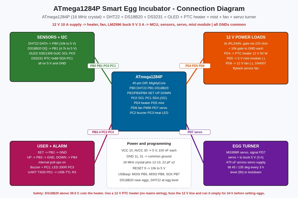
Connection Diagram
The diagram above shows the blocks and power paths. The drawing below lists every pin exactly as used in the code.
Power Supply
- A 12 V 10 A supply feeds the PTC heater (about 4 A) and the fan directly through a 10 A fuse.
- An LM2596 buck converter, set to 5.0 V before connecting anything, powers the ATmega1284P, sensors, OLED, mist module and servo. The MG996R can pull over 1 A when it starts, so add a 470 µF capacitor at the servo connector.
- All grounds meet at one point near the MOSFETs. Do not run the heater current through thin breadboard wires.
Code
The sketch is written for the Arduino IDE with the MightyCore board package. It was compile-checked for ATmega1284, standard pinout, external 16 MHz crystal: about 28 KB of flash (21 %) and 876 bytes of RAM, with no warnings. Install these libraries from the Library Manager: DHT sensor library (Adafruit), OneWire, DallasTemperature, RTClib, Adafruit GFX and Adafruit SSD1306. Servo, Wire and EEPROM come with the core.
/*
  ATmega1284P Smart Egg Incubator
  DHT22 (air temp + humidity), DS18B20 (independent over-temperature guard),
  12 V PTC heater with PI time-proportional control, 5 V ultrasonic mist
  humidifier, 12 V circulation fan, MG996R servo egg turner,
  DS3231 RTC day counter (survives power cuts), 0.96" SSD1306 OLED,
  3 buttons (SET / UP / DOWN), buzzer alarm and CSV log on UART0.

  Board : MightyCore -> "ATmega1284", standard pinout, 16 MHz external crystal
  Libs  : DHT sensor library, OneWire, DallasTemperature, RTClib,
          Adafruit GFX, Adafruit SSD1306, Servo (all from Library Manager)
  Arduino Project Hub - original example code.
*/
#include <Wire.h>
#include <EEPROM.h>
#include <Servo.h>
#include <DHT.h>
#include <OneWire.h>
#include <DallasTemperature.h>
#include <RTClib.h>
#include <Adafruit_GFX.h>
#include <Adafruit_SSD1306.h>

// ---------------- Pins (MightyCore standard pinout) ----------------
const uint8_t PIN_DHT      = PIN_PB0;  // D0  (pin 1)  DHT22 DATA, 10k pull-up
const uint8_t PIN_DS18B20  = PIN_PB1;  // D1  (pin 2)  DS18B20 DQ, 4.7k pull-up
const uint8_t PIN_BTN_SET  = PIN_PB2;  // D2  (pin 3)  button to GND
const uint8_t PIN_BTN_UP   = PIN_PB3;  // D3  (pin 4)  button to GND
const uint8_t PIN_BTN_DOWN = PIN_PB4;  // D4  (pin 5)  button to GND
const uint8_t PIN_HEATER   = PIN_PD4;  // D12 (pin 18) MOSFET gate -> PTC heater
const uint8_t PIN_MIST     = PIN_PD5;  // D13 (pin 19) MOSFET gate -> mist module
const uint8_t PIN_FAN      = PIN_PD6;  // D14 (pin 20) MOSFET gate -> fan (PWM, OC2B)
const uint8_t PIN_SERVO    = PIN_PD7;  // D15 (pin 21) servo signal
const uint8_t PIN_BUZZER   = PIN_PC2;  // D18 (pin 24) active buzzer +
const uint8_t PIN_LED_HEAT = PIN_PC3;  // D19 (pin 25) heater LED via 330R
// I2C: SCL = PC0 (pin 22), SDA = PC1 (pin 23) -> OLED 0x3C + DS3231 0x68
// UART0: RXD0 = PD0 (pin 14), TXD0 = PD1 (pin 15) -> USB-TTL for CSV log

// ---------------- Species presets ----------------
struct Species {
  const char *name;
  float tempC;        // incubation temperature
  uint8_t rhSetter;   // humidity % during setting period
  uint8_t rhLock;     // humidity % during lockdown
  uint8_t lockDay;    // first lockdown day (turning stops)
  uint8_t hatchDay;   // expected hatch day
};
const Species SPECIES[] = {
  {"Chicken", 37.5, 50, 65, 19, 21},
  {"Duck",    37.5, 55, 70, 26, 28},
  {"Quail",   37.6, 45, 65, 15, 17},
};
const uint8_t SPECIES_COUNT = sizeof(SPECIES) / sizeof(SPECIES[0]);

// ---------------- Tunable constants ----------------
const float    TEMP_ALARM_BAND   = 1.0;     // alarm if |T - target| > 1.0 C
const float    TEMP_CUTOFF_C     = 39.5;    // DS18B20 hard cut-off
const uint8_t  RH_HYSTERESIS     = 3;       // mist on below set-3, off at set
const uint32_t HEAT_WINDOW_MS    = 10000UL; // time-proportional window
const float    KP = 25.0;                   // % output per C error
const float    KI = 0.04;                   // % output per C per second
const uint32_t TURN_INTERVAL_MS  = 3UL * 3600UL * 1000UL; // turn every 3 h
const uint8_t  TILT_LEFT  = 45, TILT_RIGHT = 135;          // servo angles
const uint32_t WARMUP_MS         = 60UL * 60UL * 1000UL;  // no temp alarm 1st hour
const uint32_t MUTE_MS           = 30UL * 60UL * 1000UL;  // SET mutes 30 min
const uint8_t  FAN_NORMAL = 170, FAN_FULL = 255;          // PWM 0-255

// ---------------- EEPROM layout ----------------
const int EE_MAGIC = 0, EE_SPECIES = 1, EE_TEMP = 2, EE_RH = 6, EE_START = 8;
const uint8_t MAGIC = 0x77;

// ---------------- Objects ----------------
DHT dht(PIN_DHT, DHT22);
OneWire oneWire(PIN_DS18B20);
DallasTemperature ds(&oneWire);
RTC_DS3231 rtc;
Adafruit_SSD1306 oled(128, 64, &Wire, -1);
Servo turner;

// ---------------- State ----------------
uint8_t  speciesIdx = 0;
float    targetT = 37.5;      // user target (may differ from preset)
int8_t   rhTrim = 0;
uint32_t startUnix = 0;       // hatch start (RTC unix time)
bool     rtcOk = false;

float airT = NAN, airRH = NAN, probeT = NAN;
uint8_t dhtFailCount = 0;
float   integral = 0, heatPct = 0;
bool    mistOn = false, heaterOn = false, safetyTrip = false;
uint32_t windowStart = 0, lastRead = 0, lastLog = 0, lastTurn = 0, bootMs = 0;
uint32_t muteUntil = 0;
uint8_t  tiltPos = TILT_LEFT, tiltTarget = TILT_LEFT;
uint32_t lastServoStep = 0;
char     alarmText[18] = "";

// menu: 0 = run screen, 1 species, 2 temp, 3 humidity trim, 4 new hatch
uint8_t menu = 0;
bool    newHatchYes = false;

// ---------------- Helpers ----------------
uint16_t currentDay() {                 // day 1 = first 24 h
  if (!rtcOk || startUnix == 0) return 1;
  uint32_t now = rtc.now().unixtime();
  if (now < startUnix) return 1;
  return (uint16_t)((now - startUnix) / 86400UL) + 1;
}
bool inLockdown() { return currentDay() >= SPECIES[speciesIdx].lockDay; }
uint8_t targetRH() {
  int v = (inLockdown() ? SPECIES[speciesIdx].rhLock : SPECIES[speciesIdx].rhSetter) + rhTrim;
  return (uint8_t)constrain(v, 30, 80);
}

void saveSettings() {
  EEPROM.update(EE_MAGIC, MAGIC);
  EEPROM.update(EE_SPECIES, speciesIdx);
  EEPROM.put(EE_TEMP, targetT);
  EEPROM.update(EE_RH, (uint8_t)(rhTrim + 50));
  EEPROM.put(EE_START, startUnix);
}
void loadSettings() {
  if (EEPROM.read(EE_MAGIC) != MAGIC) { saveSettings(); return; }
  speciesIdx = EEPROM.read(EE_SPECIES);
  if (speciesIdx >= SPECIES_COUNT) speciesIdx = 0;
  EEPROM.get(EE_TEMP, targetT);
  if (isnan(targetT) || targetT < 35.0 || targetT > 39.0) targetT = SPECIES[speciesIdx].tempC;
  rhTrim = (int8_t)EEPROM.read(EE_RH) - 50;
  if (rhTrim < -15 || rhTrim > 15) rhTrim = 0;
  EEPROM.get(EE_START, startUnix);
}

// Button with debounce; returns 1 = short press, 2 = long press (SET only)
uint8_t readButton(uint8_t pin, uint32_t &downAt, bool &wasDown) {
  bool down = digitalRead(pin) == LOW;
  uint8_t ev = 0;
  if (down && !wasDown) downAt = millis();
  if (!down && wasDown) {
    uint32_t held = millis() - downAt;
    if (held > 1500) ev = 2; else if (held > 40) ev = 1;
  }
  wasDown = down;
  return ev;
}

// ---------------- Sensors ----------------
void readSensors() {
  float t = dht.readTemperature();
  float h = dht.readHumidity();
  if (isnan(t) || isnan(h)) {
    if (dhtFailCount < 255) dhtFailCount++;
  } else {
    dhtFailCount = 0; airT = t; airRH = h;
  }
  ds.requestTemperatures();             // blocking ~750 ms at 12-bit (set 10-bit below)
  float p = ds.getTempCByIndex(0);
  probeT = (p == DEVICE_DISCONNECTED_C) ? NAN : p;
}

// The control temperature: DHT22, or DS18B20 if the DHT22 has failed
float controlTemp() {
  if (dhtFailCount < 5 && !isnan(airT)) return airT;
  return probeT;
}

// ---------------- Heater: PI + time-proportional window ----------------
void updateHeaterPower(float dtSec) {
  float t = controlTemp();
  if (isnan(t)) { heatPct = 0; integral = 0; return; }
  float err = targetT - t;
  float p = KP * err;
  // anti-windup: integrate only while the output is not saturated
  if ((heatPct > 0 && heatPct < 100) || (heatPct >= 100 && err < 0) || (heatPct <= 0 && err > 0))
    integral += KI * err * dtSec;
  integral = constrain(integral, 0, 60);
  heatPct = constrain(p + integral, 0, 100);
}
void driveHeater() {
  uint32_t now = millis();
  if (now - windowStart >= HEAT_WINDOW_MS) windowStart += HEAT_WINDOW_MS;
  bool on = (now - windowStart) < (uint32_t)(heatPct * HEAT_WINDOW_MS / 100.0);
  if (safetyTrip || isnan(controlTemp())) on = false;
  heaterOn = on;
  digitalWrite(PIN_HEATER, on);
  digitalWrite(PIN_LED_HEAT, on);
}

// ---------------- Humidity, fan, turner ----------------
void updateMist() {
  if (dhtFailCount >= 5 || isnan(airRH)) { mistOn = false; }
  else if (airRH < targetRH() - RH_HYSTERESIS) mistOn = true;
  else if (airRH >= targetRH()) mistOn = false;
  digitalWrite(PIN_MIST, mistOn);
}
void updateFan() {
  float t = controlTemp();
  bool hot = safetyTrip || (!isnan(t) && t > targetT + 0.8);
  analogWrite(PIN_FAN, hot ? FAN_FULL : FAN_NORMAL);
}
void updateTurner() {
  uint32_t now = millis();
  if (!inLockdown() && now - lastTurn >= TURN_INTERVAL_MS) {
    lastTurn = now;
    tiltTarget = (tiltTarget == TILT_LEFT) ? TILT_RIGHT : TILT_LEFT;
    Serial.println(F("# egg turn"));
  }
  // in lockdown, park the tray level (90 degrees) so chicks can move freely
  uint8_t goal = inLockdown() ? 90 : tiltTarget;
  if (tiltPos != goal && now - lastServoStep >= 40) {   // slow: 1 degree / 40 ms
    lastServoStep = now;
    tiltPos += (goal > tiltPos) ? 1 : -1;
    turner.write(tiltPos);
  }
}

// ---------------- Alarms ----------------
void updateAlarms() {
  alarmText[0] = 0;
  float t = controlTemp();
  safetyTrip = (!isnan(probeT) && probeT >= TEMP_CUTOFF_C) || (!isnan(t) && t >= TEMP_CUTOFF_C);
  if (safetyTrip) strcpy(alarmText, "OVER TEMP! CUT");
  else if (isnan(t)) strcpy(alarmText, "SENSOR FAIL");
  else if (dhtFailCount >= 5) strcpy(alarmText, "DHT22 FAIL");
  else if (millis() - bootMs > WARMUP_MS && fabs(t - targetT) > TEMP_ALARM_BAND)
    strcpy(alarmText, t > targetT ? "TEMP HIGH" : "TEMP LOW");
  else if (!rtcOk) strcpy(alarmText, "RTC MISSING");
  else if (!isnan(airRH) && airRH < 35) strcpy(alarmText, "ADD WATER");

  bool beep = alarmText[0] && (safetyTrip || (int32_t)(millis() - muteUntil) >= 0);
  digitalWrite(PIN_BUZZER, beep && ((millis() / 500) % 2));   // 1 Hz beep
}

// ---------------- Display ----------------
void drawRun() {
  const Species &s = SPECIES[speciesIdx];
  oled.setTextSize(1);
  oled.setCursor(0, 0);
  oled.print(s.name); oled.print(F(" Day ")); oled.print(currentDay());
  oled.print('/'); oled.print(s.hatchDay);
  if (inLockdown()) oled.print(F(" LOCK"));
  oled.setTextSize(2);
  oled.setCursor(0, 12);
  if (isnan(controlTemp())) oled.print(F("--.-")); else oled.print(controlTemp(), 1);
  oled.print(F("C"));
  oled.setCursor(84, 12);
  if (isnan(airRH)) oled.print(F("--")); else oled.print((int)airRH);
  oled.print('%');
  oled.setTextSize(1);
  oled.setCursor(0, 32);
  oled.print(F("Set ")); oled.print(targetT, 1); oled.print(F("C "));
  oled.print(targetRH()); oled.print(F("%  H")); oled.print((int)heatPct); oled.print('%');
  oled.setCursor(0, 42);
  oled.print(F("Probe ")); if (isnan(probeT)) oled.print(F("--")); else oled.print(probeT, 1);
  oled.print(mistOn ? F(" MIST") : F("     "));
  oled.print(F(" T")); oled.print(tiltPos);
  oled.setCursor(0, 54);
  if (alarmText[0]) { oled.print(F("! ")); oled.print(alarmText); }
  else {
    uint32_t left = inLockdown() ? 0 : (TURN_INTERVAL_MS - (millis() - lastTurn)) / 60000UL;
    oled.print(F("Next turn ")); oled.print(left); oled.print(F(" min"));
  }
}
void drawMenu() {
  oled.setTextSize(1);
  oled.setCursor(0, 0);
  oled.print(F("SETTINGS  ")); oled.print(menu); oled.print(F("/4"));
  oled.setTextSize(2);
  oled.setCursor(0, 20);
  switch (menu) {
    case 1: oled.print(SPECIES[speciesIdx].name); break;
    case 2: oled.print(targetT, 1); oled.print('C'); break;
    case 3: oled.print(F("RH ")); if (rhTrim >= 0) oled.print('+'); oled.print(rhTrim); break;
    case 4: oled.print(F("New: ")); oled.print(newHatchYes ? F("YES") : F("NO")); break;
  }
  oled.setTextSize(1);
  oled.setCursor(0, 48);
  oled.print(F("UP/DOWN change"));
  oled.setCursor(0, 56);
  oled.print(F("SET next, hold=exit"));
}

// ---------------- Buttons / menu ----------------
uint32_t dSet, dUp, dDown; bool wSet, wUp, wDown;
void handleButtons() {
  uint8_t s = readButton(PIN_BTN_SET, dSet, wSet);
  uint8_t u = readButton(PIN_BTN_UP, dUp, wUp);
  uint8_t d = readButton(PIN_BTN_DOWN, dDown, wDown);
  if (menu == 0) {
    if (s == 1) muteUntil = millis() + MUTE_MS;           // mute alarm
    if (s == 2) { menu = 1; newHatchYes = false; }        // enter settings
    return;
  }
  int8_t step = (u == 1) ? 1 : (d == 1) ? -1 : 0;
  if (step) {
    switch (menu) {
      case 1: speciesIdx = (speciesIdx + SPECIES_COUNT + step) % SPECIES_COUNT;
              targetT = SPECIES[speciesIdx].tempC; break;
      case 2: targetT = constrain(targetT + 0.1 * step, 35.0, 39.0); break;
      case 3: rhTrim = constrain(rhTrim + step, -15, 15); break;
      case 4: newHatchYes = !newHatchYes; break;
    }
  }
  if (s == 1 && menu < 4) menu++;
  else if ((s == 1 && menu == 4) || s == 2) {               // leave and save
    if (newHatchYes && rtcOk) {
      startUnix = rtc.now().unixtime();
      lastTurn = millis();
      Serial.println(F("# new hatch started"));
    }
    saveSettings();
    menu = 0;
  }
}

// ---------------- Setup / loop ----------------
void setup() {
  // PC2-PC5 are JTAG pins: disable JTAG in software (two writes within 4 cycles)
  uint8_t m = MCUCR | (1 << JTD);
  MCUCR = m; MCUCR = m;

  pinMode(PIN_BTN_SET, INPUT_PULLUP);
  pinMode(PIN_BTN_UP, INPUT_PULLUP);
  pinMode(PIN_BTN_DOWN, INPUT_PULLUP);
  pinMode(PIN_HEATER, OUTPUT);   digitalWrite(PIN_HEATER, LOW);
  pinMode(PIN_MIST, OUTPUT);     digitalWrite(PIN_MIST, LOW);
  pinMode(PIN_FAN, OUTPUT);
  pinMode(PIN_BUZZER, OUTPUT);
  pinMode(PIN_LED_HEAT, OUTPUT);

  Serial.begin(9600);
  Wire.begin();
  dht.begin();
  ds.begin();
  ds.setResolution(10);                 // 0.25 C steps, ~190 ms conversion
  if (!oled.begin(SSD1306_SWITCHCAPVCC, 0x3C)) Serial.println(F("# OLED not found"));
  oled.setTextColor(SSD1306_WHITE);

  rtcOk = rtc.begin();
  if (rtcOk && rtc.lostPower()) rtc.adjust(DateTime(F(__DATE__), F(__TIME__)));
  loadSettings();
  if (rtcOk && startUnix == 0) { startUnix = rtc.now().unixtime(); saveSettings(); }

  turner.attach(PIN_SERVO);
  turner.write(tiltPos);
  bootMs = windowStart = lastTurn = millis();
  Serial.println(F("time_s,day,air_C,rh,probe_C,heat_pct,mist,tilt"));
}

void loop() {
  uint32_t now = millis();
  handleButtons();

  if (now - lastRead >= 2000) {         // DHT22 needs >= 2 s between reads
    float dt = (now - lastRead) / 1000.0;
    lastRead = now;
    readSensors();
    updateAlarms();
    updateHeaterPower(dt);
    updateMist();
    updateFan();
    oled.clearDisplay();
    if (menu == 0) drawRun(); else drawMenu();
    oled.display();
  }
  driveHeater();
  updateTurner();
  updateAlarms();                       // keeps the buzzer blinking smoothly

  if (now - lastLog >= 60000UL) {       // CSV line every minute
    lastLog = now;
    Serial.print(now / 1000); Serial.print(',');
    Serial.print(currentDay()); Serial.print(',');
    Serial.print(airT, 1); Serial.print(',');
    Serial.print(airRH, 0); Serial.print(',');
    Serial.print(probeT, 2); Serial.print(',');
    Serial.print(heatPct, 0); Serial.print(',');
    Serial.print(mistOn); Serial.print(',');
    Serial.println(tiltPos);
  }
}
Uploading with MightyCore
- In the Arduino IDE open File → Preferences and add the MightyCore board manager URL from the MightyCore GitHub page, then install MightyCore in the Boards Manager.
- Select Tools → Board → MightyCore → ATmega1284, Variant 1284P, Pinout Standard, Clock External 16 MHz, Bootloader Yes (UART0).
- Connect the USBasp and click Tools → Burn Bootloader once. This sets the fuses for the crystal.
- Upload with Sketch → Upload Using Programmer, or later through a USB-TTL adapter on RXD0/TXD0 with DTR wired to RESET through a 100 nF capacitor.
Setting Up and Using the Incubator
- Test empty first: run the incubator with water in the tray but no eggs for at least 24 hours. Check the OLED temperature against a trusted thermometer placed at egg height and adjust the target in the menu if needed.
- Settings menu: hold SET for 2 seconds. Use UP/DOWN to choose the species (Chicken, Duck, Quail), press SET to move to the target temperature (35.0–39.0 °C), then the humidity trim (±15 %), then New. Choose YES on the last page and press SET to start a new hatch from day 1.
- Main screen: species and day (for example Chicken Day 7/21), large temperature and humidity, the set points, heater power, probe temperature, mist state, tray angle and minutes to the next turn. LOCK appears from the lockdown day.
- Mute: a short press on SET silences a normal alarm for 30 minutes. The over-temperature alarm cannot be muted.
- Candling: open the lid only briefly. The PI controller recovers the temperature within a few minutes.
Troubleshooting
| Problem | Fix |
|---|---|
| Temperature overshoots by more than 0.5 °C | Reduce KP to 15–20 and make sure the fan really mixes the air. A heater far bigger than the box needs makes control harder. |
| Temperature stays slightly below target | Wait 20–30 minutes for the integral term to build up. If it never reaches the target, the heater is too weak or the box loses too much heat; insulate it better. |
| OLED shows DHT22 FAIL | Check the 10 kΩ pull-up on PB0 and the wiring. Long cables (over 2 m) need a lower pull-up such as 4.7 kΩ. Control continues on the DS18B20 meanwhile. |
| Probe shows — | DS18B20 not found: check the 4.7 kΩ pull-up between DQ and 5 V and the colour code of the probe wires. |
| Buzzer and LED on PC2/PC3 do nothing | JTAG is still active. Burn the bootloader with MightyCore (JTAG off) and keep the JTD lines at the start of setup(). |
| Day counter is wrong or shows RTC MISSING | Check the DS3231 on SDA/SCL and the CR2032 cell. The clock is set from the compile time if it lost power; then start a new hatch from the menu. |
| Board resets when the servo moves | The servo is drawing too much from the 5 V rail. Use a 3 A buck converter, add the 470 µF capacitor and use thick wires to the servo. |
| Humidity too high in lockdown or condensation | Lower the humidity trim, reduce the water area, or open a small vent hole. Mist alone cannot lower humidity. |
| Heater MOSFET gets hot | Use a logic-level IRLZ44N (not IRFZ44N), check the 220 Ω gate resistor and add a small heatsink. |
Safety Notes
- Use only low-voltage DC heating. Do not put mains bulbs or mains wiring inside a thermocol or wooden box.
- Keep the 10 A fuse in the 12 V line and check all heater connections for heat after the first day.
- Keep the DS18B20 cut-off connected and test it once by warming the probe in your hand above the cut-off value (temporarily lower
TEMP_CUTOFF_Cto 33 °C for the test).
Ideas to Extend
- Add an ESP-01 or HC-05 on UART1 (PD2/PD3) to send alarms to your phone.
- Add a 12 V lead-acid backup battery with a diode OR-ing circuit for long power cuts.
- Add a float switch in the water tray on a free PORTA pin to warn before the humidity drops.