
Build a no-code touch on/off switch with a CD4013 D flip-flop in toggle mode: touch the pad once to switch a lamp on through a 5 V relay, touch again to switch it off. A two-transistor Schmitt stage cleans up the touch signal, and a 7805 runs everything from a 9–12 V adapter.
Need it ready-made? Buy Ready Project
A touch switch feels modern, has no moving parts to wear out and is a great first project with logic ICs. In this CD4013 touch switch you touch a small metal pad once and a lamp turns on; touch it again and the lamp turns off. There is no microcontroller and no code – the memory of the ON/OFF state is a single D flip-flop inside the CD4013, wired in toggle mode.
The finger signal is weak and noisy, so it first passes through a debounce RC network and a two-transistor Schmitt trigger made from BC547s. That stage gives the flip-flop the clean, fast clock edge it needs. The flip-flop output drives a third BC547, which switches a 5 V relay and an indicator LED. A 7805 regulator powers the circuit from any 9–12 V DC adapter, and a small power-on reset makes sure the lamp always starts OFF after a power cut.
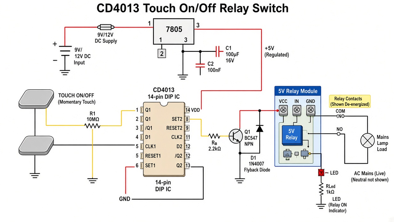
Mains safety warning: the relay contacts switch 230 V / 120 V AC, which can kill. Build and test the whole circuit first with the lamp disconnected (the LED and the relay click show the state). Connect the mains side only with the plug pulled out, use a fuse, an insulated enclosure and proper terminal blocks, and keep at least 6 mm between mains tracks and the low-voltage circuit. Never touch the board while it is plugged in. If you are not trained to work with mains wiring, ask a qualified electrician to wire the lamp side.
How It Works
- Touch pad: the pad is two copper strips about 2–3 mm apart. Strip A sits at +5 V. When your fingertip bridges both strips, the skin (roughly 0.5–3 MΩ) lets a few microamps flow from strip A through the 100 kΩ series resistor into the base of Q1. The 100 kΩ resistor also limits current and protects Q1 from static discharge.
- Debounce RC: the 4.7 MΩ resistor pulls Q1’s base firmly to ground when nobody touches the pad, and the 47 nF capacitor smooths the signal. Together they filter out 50/60 Hz hum picked up by your body and the tiny bounces of a finger landing on the pad. The 4.7 MΩ × 47 nF time constant (about 0.2 s) also means a quick double tap is read as one touch.
- Schmitt trigger (Q1 + Q2): the CD4013 clock input needs an edge faster than about 15 µs at 5 V, while the RC signal changes over milliseconds. Q1 and Q2 share one 220 Ω emitter resistor, which gives positive feedback: as soon as Q1 starts to conduct, Q2 turns off, which lowers the emitter voltage and turns Q1 on even harder. The output at Q2’s collector therefore snaps from about 0.3 V to 5 V in well under a microsecond and cannot chatter.
- Toggle flip-flop: in the CD4013, the D input (pin 5) is tied to Q̄ (pin 2). On every rising edge on CLK (pin 3), Q copies D, and since D is always the opposite of Q, the output flips: OFF → ON → OFF. Set (pin 6) is tied to VSS so it never interferes.
- Power-on reset: a 100 nF capacitor from VDD to Reset (pin 4) with a 100 kΩ resistor to VSS gives a short HIGH pulse on pin 4 when the power comes on. That clears the flip-flop, so after a power cut the lamp stays OFF instead of starting in a random state.
- Relay driver: Q (pin 1) feeds 2.2 kΩ into the base of Q3. When Q is HIGH, Q3 saturates and the relay coil (about 70 mA) and the LED switch on together. The 1N4007 across the coil catches the voltage spike when the coil switches off, protecting Q3.
- Unused second flip-flop: CMOS inputs must never float, so CLK2, R2, D2 and S2 (pins 11, 10, 9 and 8) are tied to VSS. Its outputs (pins 12 and 13) are left unconnected.
- Power supply: the 1N4007 in series with the adapter protects against a reversed plug. The 7805 makes a clean 5 V; the 100 µF and 0.33 µF capacitors at its input and the 220 µF plus 100 nF at its output keep the rail steady when the relay clicks.
Components Required
- CD4013 dual D-type flip-flop IC with 14-pin DIP socket – 1
- BC547 NPN transistors – 3 (Q1 and Q2 touch Schmitt stage, Q3 relay driver)
- 7805 5 V voltage regulator (TO-220) – 1
- 5 V SPDT relay (bare relay, not a module), e.g. SRD-05VDC-SL-C (contacts rated 10 A 250 V AC) – 1
- 1N4007 diodes – 2 (relay flyback and reverse-polarity protection)
- 5 mm LED (red or green) – 1
- 4.7 MΩ resistor (touch pull-down) – 1
- 100 kΩ resistors – 2 (touch series resistor and power-on reset)
- 10 kΩ resistors – 2 (Q1 collector load and Q1-to-Q2 coupling)
- 22 kΩ resistor (Q2 base to GND) – 1
- 4.7 kΩ resistor (Q2 collector load) – 1
- 220 Ω resistor (shared emitter resistor of Q1/Q2) – 1
- 2.2 kΩ resistor (relay transistor base) – 1
- 1 kΩ resistor (LED) – 1
- 47 nF ceramic capacitor (touch debounce) – 1
- 100 nF ceramic capacitors – 3 (CD4013 decoupling, 7805 output, power-on reset)
- 0.33 µF capacitor (7805 input) – 1
- 100 µF 25 V and 220 µF 10 V electrolytic capacitors – 1 each
- Touch pad: two copper strips about 2–3 mm apart (PCB offcut) or two metal screw heads – 1
- 9–12 V DC adapter (300 mA or more) with DC jack – 1
- Mains side: 1 A fuse with holder, 3-way screw terminal, lamp holder and AC lamp (up to 100 W), fully insulated plastic enclosure – 1 set
- Perfboard, header wire and hook-up wire – 1 set
Connection / Wiring Table
| From | To | Notes |
|---|---|---|
| CD4013 pin 14 (VDD) | +5 V rail (7805 OUT) | 100 nF ceramic from pin 14 to pin 7, close to the IC |
| CD4013 pin 7 (VSS) | GND | Common ground for everything |
| CD4013 pin 3 (CLK1) | Q2 collector | Clean clock from the Schmitt stage |
| CD4013 pin 5 (D1) | CD4013 pin 2 (Q̄1) | Short wire link – this makes the toggle |
| CD4013 pin 1 (Q1) | 2.2 kΩ → Q3 base | HIGH = relay ON |
| CD4013 pin 4 (R1) | 100 nF to +5 V and 100 kΩ to GND | Power-on reset (lamp starts OFF) |
| CD4013 pin 6 (S1) | GND | Set input not used |
| CD4013 pins 8, 9, 10, 11 (S2, D2, R2, CLK2) | GND | Unused flip-flop 2 inputs – never leave floating |
| CD4013 pins 12, 13 (Q̄2, Q2) | Not connected | Unused outputs |
| Touch pad strip A | +5 V | Outer strip |
| Touch pad strip B | 100 kΩ → Q1 base | Keep this wire short |
| Q1 base | 4.7 MΩ to GND and 47 nF to GND | Pull-down + debounce RC |
| Q1 collector | 10 kΩ to +5 V and 10 kΩ to Q2 base | Q2 base also has 22 kΩ to GND |
| Q1 emitter and Q2 emitter | 220 Ω → GND | One shared resistor – this gives the hysteresis |
| Q2 collector | 4.7 kΩ to +5 V and CD4013 pin 3 | Schmitt output |
| Q3 (BC547) emitter | GND | Relay driver |
| Q3 collector | Relay coil (other end at +5 V) | Also the LED cathode |
| 1N4007 (flyback) | Across the relay coil | Stripe (cathode) to +5 V |
| LED | +5 V → 1 kΩ → LED anode, cathode → Q3 collector | Lights when the relay is ON |
| Adapter + (9–12 V) | 1N4007 anode; cathode → 7805 pin 1 (IN) | Reverse-polarity protection |
| 7805 pin 2 (GND) / pin 3 (OUT) | GND / +5 V rail | 100 µF + 0.33 µF on input, 220 µF + 100 nF on output |
| Relay COM | Mains LIVE through a 1 A fuse | Mains side – see the safety warning |
| Relay NO | Lamp, other lamp wire → mains NEUTRAL | NC terminal is not used |
BC547 pinout (flat face towards you, legs down): Collector – Base – Emitter from left to right. 7805 (text facing you): IN – GND – OUT.
Connection Diagram
This pin-accurate diagram is the authoritative wiring for the project; it matches the wiring table pin for pin.
Code
No code is needed for this project. The CD4013 is a non-programmable logic IC: the toggle behaviour comes entirely from the wiring (D tied to Q̄), so there is nothing to upload and no programmer is required. Just build, check the wiring and power it up.
Testing Step by Step
- Power only: with the CD4013 out of its socket, connect the adapter and measure 5 V between socket pins 14 and 7. If the reading is 0 V, check the 1N4007 direction and the 7805 pin order.
- Schmitt stage: measure Q2’s collector – it should read about 0.3 V when idle and jump to about 5 V while you touch the pad.
- Flip-flop: insert the CD4013 the right way round (the notch and the dot mark pin 1). Power up – the LED must be OFF thanks to the power-on reset. Each touch should now toggle the LED and click the relay.
- Mains last: only when the low-voltage side works perfectly, unplug everything, wire the lamp through the fuse and the relay COM/NO contacts, close the enclosure and then plug in.
Troubleshooting
| Problem | Fix |
|---|---|
| Nothing happens when touching | Check that strip A really has +5 V and that the fingertip bridges both strips. Very dry skin has a high resistance – moisten the fingertip slightly, move the strips closer (2 mm) or use a BC547C (higher gain) for Q1. |
| Lamp toggles twice or flickers on one touch | The clock edge is not clean. Check the shared 220 Ω emitter resistor and the 47 nF debounce capacitor, keep the pad wire short and do not run it next to the mains wires. |
| Switches on by itself | The 4.7 MΩ pull-down is missing or the pad is damp or dirty. Clean the pad, add a thin varnish gap between the strips only, and keep the board away from mains cables. Make sure pins 6, 8, 9, 10 and 11 are tied to GND. |
| LED toggles but the relay does not click | Check the relay is a 5 V coil type, the Q3 pin order (C-B-E) and the 2.2 kΩ base resistor. Measure about 0.7 V on Q3 base when ON. |
| Lamp is ON after a power cut | The power-on reset is missing: 100 nF from +5 V to pin 4 and 100 kΩ from pin 4 to GND. |
| Circuit resets or toggles when the relay clicks | Add or check the 220 µF capacitor on the 5 V rail and the 100 nF decoupling at pins 14–7. Confirm the 1N4007 flyback diode is fitted with the stripe to +5 V. |
| 7805 gets hot | Normal at 12 V input with the relay ON (about 0.5 W). Use a 9 V adapter or a small heatsink. |
| Relay clicks but the lamp stays off | Lamp wired to NC instead of NO, blown fuse or loose terminal. Unplug from mains before checking! |
Ideas to Extend
- Use the second flip-flop of the CD4013 with another touch pad and a second relay for a two-channel touch switch board.
- Add a CD4060 delay so the lamp switches off automatically after a set time.
- Replace the relay with a MOC3041 optocoupler and a triac for silent switching of resistive loads (advanced, mains work).
- Put a small LED behind a frosted touch pad so it glows when the lamp is on – easy to find in the dark.