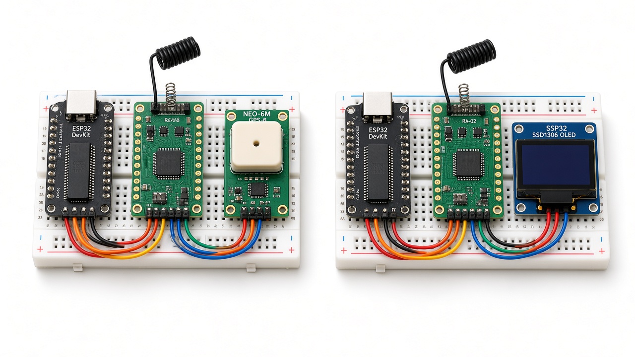
LoRa GPS Tracker with ESP32, Ra-02 SX1278 and NEO-6M (Transmitter + OLED Receiver)

Two ESP32 breadboard setups for a LoRa GPS tracker, with Ra-02 modules, a NEO-6M GPS and an OLED receiver

Build a long-range LoRa GPS tracker with two ESP32 boards, Ra-02 SX1278 modules and a NEO-6M GPS. Wiring tables, two tested sketches, OLED receiver with RSSI, range tips and Hindi explanation.

  • DifficultyAdvanced
  • Build time5–8 hours
  • Board / MCUESP32 DevKit
  • Parts7 items
  • CodeArduino C++

Need it ready-made? Buy Ready Project

Two ESP32 breadboard setups for a LoRa GPS tracker, with Ra-02 modules, a NEO-6M GPS and an OLED receiver

Wi-Fi reaches a few tens of metres and mobile data needs a SIM card and a monthly plan. LoRa (Long Range) radio can send small packets over several kilometres with no network, no SIM and very little power. In this intermediate project we combine LoRa with GPS to build a LoRa GPS tracker using two ESP32 boards, Ra-02 (SX1278) modules and a NEO-6M GPS. The transmitter reads its position from the GPS every 5 seconds and broadcasts it by LoRa; the receiver shows latitude, longitude, speed, number of satellites and signal strength (RSSI/SNR) on an OLED display and prints a Google Maps link on the Serial Monitor.

It is a great project for tracking a bicycle, a pet, a drone, a farm vehicle or a hiking partner in an area without mobile coverage. Below you will find the parts list, wiring tables for both nodes, two compile-tested sketches, a detailed explanation, step-by-step build, range tips, troubleshooting, FAQ and a simple Hindi explanation.

How the System Works

The NEO-6M GPS module continuously outputs NMEA sentences (text like $GPGGA,…) at 9600 baud. The TinyGPSPlus library parses these sentences into easy values: latitude, longitude, altitude, speed and satellite count. Every 5 seconds the transmitter ESP32 builds a short comma-separated message such as TRK1,25,22.572645,88.363892,12.4,3.1,8 and sends it through the Ra-02 module using the arduino-LoRa library.

The receiver ESP32 listens on the same frequency, spreading factor and sync word. When a packet arrives it splits the fields, reads the packet RSSI (received signal strength in dBm) and SNR (signal-to-noise ratio), and displays everything on a 128×64 SSD1306 OLED. If no packet arrives for 30 seconds, it shows “Signal lost!”. The TRK1 prefix lets the receiver ignore packets from other LoRa devices nearby.

Components Required

  • ESP32 DevKit V1 – 2 (one transmitter, one receiver)
  • Ra-02 SX1278 LoRa module 433 MHz with antenna – 2 (or RFM95/RA-01H 868 MHz modules – see the frequency note)
  • NEO-6M GPS module (GY-NEO6MV2) with ceramic patch antenna – 1
  • 0.96″ SSD1306 I2C OLED (128×64) – 1 (receiver)
  • Breadboards or perfboard, jumper wires
  • 2 × USB cables or power banks for field testing
  • Optional: 2.54 mm adapter board for the Ra-02 (its pins are 2 mm pitch)

Frequency note: Ra-02 modules work at 433 MHz. Always check your local radio regulations. In India the common LoRa band is 865–867 MHz – if you use 868 MHz modules (e.g. RFM95W or Ra-01H), change LORA_FREQ to 866E6 in both sketches. Both nodes must use the same frequency and settings.

Wiring Table – Transmitter (ESP32 + Ra-02 + NEO-6M)

ModuleModule PinESP32 PinNotes
Ra-023.3V3V33.3 V only – 5 V will destroy the module
Ra-02GNDGND
Ra-02NSS (CS)GPIO5LORA_NSS 5
Ra-02SCKGPIO18VSPI clock
Ra-02MISOGPIO19
Ra-02MOSIGPIO23
Ra-02RSTGPIO14LORA_RST 14
Ra-02DIO0GPIO2LORA_DIO0 2 – packet-done interrupt
Ra-02Antenna (IPEX)433 MHz antennaNever transmit without an antenna
NEO-6MVCC3V3 (or VIN/5V)GY-NEO6MV2 has an on-board regulator
NEO-6MGNDGND
NEO-6MTXGPIO16 (RX2)GPS_RX_PIN 16
NEO-6MRXGPIO17 (TX2)GPS_TX_PIN 17 (optional, used for configuration)

Wiring Table – Receiver (ESP32 + Ra-02 + OLED)

ModuleModule PinESP32 PinNotes
Ra-023.3V / GND3V3 / GND
Ra-02NSS / SCK / MISO / MOSIGPIO5 / 18 / 19 / 23Same as transmitter
Ra-02RST / DIO0GPIO14 / GPIO2Same as transmitter
SSD1306 OLEDVCC / GND3V3 / GND
SSD1306 OLEDSDAGPIO21OLED_SDA 21
SSD1306 OLEDSCLGPIO22OLED_SCL 22

Libraries Used (with Licenses)

Transmitter Code (GPS + LoRa)

Compile-tested for ESP32 Dev Module (Espressif core 3.x) with LoRa 0.8.0 and TinyGPSPlus 1.0.3.

// LoRa GPS Tracker - TRANSMITTER
// ESP32 DevKit + Ra-02 (SX1278) LoRa module + NEO-6M GPS
// Libraries: LoRa by Sandeep Mistry (MIT), TinyGPSPlus by Mikal Hart (LGPL-2.1)
#include <SPI.h>
#include <LoRa.h>
#include <TinyGPSPlus.h>

#define LORA_SCK   18
#define LORA_MISO  19
#define LORA_MOSI  23
#define LORA_NSS   5
#define LORA_RST   14
#define LORA_DIO0  2
#define LORA_FREQ  433E6      // Ra-02 = 433 MHz. Use 866E6 with an 868 MHz module (India 865-867 MHz)

#define GPS_RX_PIN 16         // ESP32 RX2  <- NEO-6M TX
#define GPS_TX_PIN 17         // ESP32 TX2  -> NEO-6M RX
#define GPS_BAUD   9600

TinyGPSPlus gps;
HardwareSerial gpsSerial(2);
unsigned long packetCount = 0;
unsigned long lastSend = 0;
const unsigned long SEND_INTERVAL = 5000;   // send every 5 seconds

void setup() {
  Serial.begin(115200);
  gpsSerial.begin(GPS_BAUD, SERIAL_8N1, GPS_RX_PIN, GPS_TX_PIN);

  SPI.begin(LORA_SCK, LORA_MISO, LORA_MOSI, LORA_NSS);
  LoRa.setPins(LORA_NSS, LORA_RST, LORA_DIO0);
  if (!LoRa.begin(LORA_FREQ)) {
    Serial.println("LoRa init failed - check wiring");
    while (true) delay(1000);
  }
  LoRa.setSyncWord(0xA5);          // must match the receiver
  LoRa.setSpreadingFactor(10);     // longer range, slower data
  LoRa.setSignalBandwidth(125E3);
  LoRa.setTxPower(17);
  LoRa.enableCrc();
  Serial.println("LoRa GPS transmitter ready");
}

void loop() {
  // keep feeding NMEA characters to TinyGPSPlus
  while (gpsSerial.available()) {
    gps.encode(gpsSerial.read());
  }

  if (millis() - lastSend >= SEND_INTERVAL) {
    lastSend = millis();
    packetCount++;

    String msg = "TRK1,";
    msg += String(packetCount) + ",";
    if (gps.location.isValid()) {
      msg += String(gps.location.lat(), 6) + ",";
      msg += String(gps.location.lng(), 6) + ",";
      msg += String(gps.altitude.meters(), 1) + ",";
      msg += String(gps.speed.kmph(), 1) + ",";
    } else {
      msg += "0,0,0,0,";            // no fix yet
    }
    msg += String(gps.satellites.isValid() ? gps.satellites.value() : 0);

    LoRa.beginPacket();
    LoRa.print(msg);
    LoRa.endPacket();

    Serial.print("Sent: ");
    Serial.println(msg);
    if (gps.charsProcessed() < 10) {
      Serial.println("No data from GPS - check TX/RX wiring");
    }
  }
}

Receiver Code (LoRa + OLED)

Compile-tested for ESP32 Dev Module with LoRa 0.8.0 and Adafruit SSD1306 2.5.x.

// LoRa GPS Tracker - RECEIVER
// ESP32 DevKit + Ra-02 (SX1278) + 0.96" SSD1306 OLED
// Libraries: LoRa by Sandeep Mistry (MIT), Adafruit SSD1306 + Adafruit GFX (BSD)
#include <SPI.h>
#include <LoRa.h>
#include <Wire.h>
#include <Adafruit_GFX.h>
#include <Adafruit_SSD1306.h>

#define LORA_SCK   18
#define LORA_MISO  19
#define LORA_MOSI  23
#define LORA_NSS   5
#define LORA_RST   14
#define LORA_DIO0  2
#define LORA_FREQ  433E6

#define OLED_SDA   21
#define OLED_SCL   22
Adafruit_SSD1306 display(128, 64, &Wire, -1);

unsigned long lastPacketMs = 0;

// split "TRK1,count,lat,lng,alt,speed,sats" into fields
String field(const String &s, int index) {
  int found = 0, start = 0;
  for (int i = 0; i <= (int)s.length(); i++) {
    if (i == (int)s.length() || s.charAt(i) == ',') {
      if (found == index) return s.substring(start, i);
      found++;
      start = i + 1;
    }
  }
  return "";
}

void showText(const String &l1, const String &l2, const String &l3, const String &l4, const String &l5) {
  display.clearDisplay();
  display.setTextSize(1);
  display.setTextColor(SSD1306_WHITE);
  display.setCursor(0, 0);  display.println(l1);
  display.setCursor(0, 13); display.println(l2);
  display.setCursor(0, 26); display.println(l3);
  display.setCursor(0, 39); display.println(l4);
  display.setCursor(0, 52); display.println(l5);
  display.display();
}

void setup() {
  Serial.begin(115200);
  Wire.begin(OLED_SDA, OLED_SCL);
  if (!display.begin(SSD1306_SWITCHCAPVCC, 0x3C)) {
    Serial.println("OLED not found");
  }
  showText("LoRa GPS Receiver", "Starting...", "", "", "");

  SPI.begin(LORA_SCK, LORA_MISO, LORA_MOSI, LORA_NSS);
  LoRa.setPins(LORA_NSS, LORA_RST, LORA_DIO0);
  if (!LoRa.begin(LORA_FREQ)) {
    Serial.println("LoRa init failed");
    showText("LoRa init failed", "Check wiring", "", "", "");
    while (true) delay(1000);
  }
  LoRa.setSyncWord(0xA5);
  LoRa.setSpreadingFactor(10);
  LoRa.setSignalBandwidth(125E3);
  LoRa.enableCrc();
  showText("LoRa GPS Receiver", "Waiting for", "tracker...", "", "");
}

void loop() {
  int packetSize = LoRa.parsePacket();
  if (packetSize) {
    String msg = "";
    while (LoRa.available()) msg += (char)LoRa.read();
    int rssi = LoRa.packetRssi();
    float snr = LoRa.packetSnr();
    lastPacketMs = millis();

    if (!msg.startsWith("TRK1,")) return;   // ignore other LoRa devices
    String count = field(msg, 1);
    String lat   = field(msg, 2);
    String lng   = field(msg, 3);
    String spd   = field(msg, 5);
    String sats  = field(msg, 6);

    Serial.print("Received: "); Serial.print(msg);
    Serial.print("  RSSI: "); Serial.print(rssi);
    Serial.print("  SNR: "); Serial.println(snr);

    if (lat == "0" && lng == "0") {
      showText("Pkt #" + count, "GPS: no fix yet", "Sats: " + sats, "RSSI: " + String(rssi) + " dBm", "SNR: " + String(snr, 1));
    } else {
      Serial.println("Map: https://maps.google.com/?q=" + lat + "," + lng);
      showText("Pkt #" + count + " Sats:" + sats, "Lat: " + lat, "Lng: " + lng, "Spd: " + spd + " km/h", "RSSI:" + String(rssi) + " SNR:" + String(snr, 1));
    }
  }

  if (lastPacketMs > 0 && millis() - lastPacketMs > 30000) {
    showText("Signal lost!", "No packet for", "30 seconds", "", "");
    lastPacketMs = millis();
  }
}

Code Explanation

  • HardwareSerial gpsSerial(2) uses the ESP32’s second hardware UART on GPIO16/17, so the USB serial port stays free for debugging.
  • gps.encode() is called for every character, all the time. Never put long delay() calls in the transmitter loop or the GPS buffer overflows.
  • SPI.begin(18, 19, 23, 5) and LoRa.setPins(5, 14, 2) tell the library which pins the Ra-02 uses.
  • Radio settings: spreading factor 10 and 125 kHz bandwidth trade speed for range – a packet of ~40 bytes takes around 0.4 s on air, which is fine for a 5-second interval. Sync word 0xA5 and CRC must match on both nodes.
  • Message format: TRK1,count,lat,lng,alt,speed,sats. Before the GPS gets a fix, it sends zeros so you can still test the radio link indoors.
  • field() in the receiver splits the comma-separated message without using extra memory-hungry libraries.
  • RSSI and SNR tell you link quality: RSSI around −120 dBm and SNR below −10 dB means you are near the edge of range.

Step-by-Step Build Instructions

  1. Install the ESP32 board package and, from Library Manager, install LoRa (Sandeep Mistry), TinyGPSPlus (Mikal Hart) and Adafruit SSD1306 (with Adafruit GFX).
  2. Solder the antennas or attach the IPEX antennas to both Ra-02 modules before powering them.
  3. Wire the transmitter: Ra-02 to the SPI pins and the NEO-6M to GPIO16/17 as in the first table.
  4. Wire the receiver: Ra-02 the same way plus the OLED on GPIO21/22.
  5. Upload lora_tx to the transmitter and lora_rx to the receiver. Keep both connected to USB for the first test.
  6. Open the receiver’s Serial Monitor at 115200 baud. Even indoors you should see packets like TRK1,3,0,0,0,0,0 and the OLED shows “GPS: no fix yet” with RSSI.
  7. Take the transmitter outdoors or to a window with a clear sky. The NEO-6M LED starts blinking once it has a fix (the first fix may take 1–5 minutes).
  8. Now the receiver shows the real coordinates and prints a Google Maps link. Power the transmitter from a power bank and walk or drive away while watching RSSI to test range.

सरल हिंदी में समझें (Simple Hindi Explanation)

यह प्रोजेक्ट दो हिस्सों में है – ट्रांसमीटर और रिसीवर। ट्रांसमीटर ESP32 से NEO-6M GPS जुड़ा है जो सैटेलाइट से अपनी लोकेशन (latitude, longitude) निकालता है। हर 5 सेकंड में ESP32 यह लोकेशन LoRa रेडियो (Ra-02) से भेजता है। LoRa की खासियत है कि यह बिना इंटरनेट और बिना सिम कार्ड के कई किलोमीटर तक छोटा डेटा भेज सकता है।

रिसीवर ESP32 उसी फ्रीक्वेंसी पर सुनता है और मिली हुई लोकेशन, स्पीड, सैटेलाइट की संख्या और सिग्नल की ताकत (RSSI) को OLED स्क्रीन पर दिखाता है। Serial Monitor में Google Maps का लिंक भी आता है जिसे खोलकर आप ट्रैकर की जगह देख सकते हैं। ध्यान दें: Ra-02 मॉड्यूल को सिर्फ 3.3V दें और एंटीना लगाए बिना कभी चालू न करें। अपने देश के नियम के अनुसार सही फ्रीक्वेंसी (भारत में आमतौर पर 865–867 MHz) चुनें।

Tips for Better Range

  • Use proper tuned antennas for your frequency, mounted vertically and as high as possible.
  • Line of sight matters most: buildings and trees reduce range sharply. 1–3 km in a city and 5 km+ in open fields is typical with SF10.
  • Increase spreading factor to 11 or 12 for more range (slower packets). Change it on both nodes.
  • Keep the antenna away from the ESP32 and the GPS antenna to reduce interference.

Troubleshooting

ProblemFix
“LoRa init failed”Check NSS, RST and SPI wires and 3.3 V power. The Ra-02 2 mm pins often make poor contact on breadboards – use an adapter board or solder.
Receiver gets nothingFrequency, spreading factor, bandwidth and sync word must be identical in both sketches. Check that both antennas are connected.
“No data from GPS”Swap TX/RX – NEO-6M TX must go to GPIO16. Check that the GPS baud rate is 9600.
GPS never gets a fixGo outdoors with a clear view of the sky and wait up to 5 minutes. Indoors the NEO-6M usually cannot see enough satellites.
OLED blank on receiverCheck SDA/SCL on 21/22 and the address (0x3C or 0x3D).
Very short rangeMissing or wrong-frequency antenna, or the module was damaged by transmitting without an antenna.

Frequently Asked Questions

Is this LoRaWAN?

No. This is point-to-point LoRa: one radio talks directly to another. LoRaWAN uses gateways and a network server such as The Things Network and needs a different library.

Can I use TTGO LoRa32 or Heltec WiFi LoRa 32 boards?

Yes – they have an ESP32 and an SX127x on one board. Change the pin numbers to match the board (for example TTGO LoRa32 v1: SCK 5, MISO 19, MOSI 27, NSS 18, RST 14, DIO0 26; OLED SDA 4, SCL 15, OLED reset 16). Always confirm against the pinout of your exact board version.

How much battery does the transmitter use?

Roughly 100–150 mA average with the ESP32 awake. For long battery life, put the ESP32 into deep sleep between transmissions and power the GPS through a switch.

Can I send the position to the internet?

Yes – connect the receiver ESP32 to Wi-Fi and post the data to a server, MQTT broker or Google Sheet.

How accurate is the NEO-6M?

About 2.5 m in open sky according to the datasheet; 5–10 m is typical in real use.

Related Projects

Browse more ESP32 Projects on Arduino Project Hub.
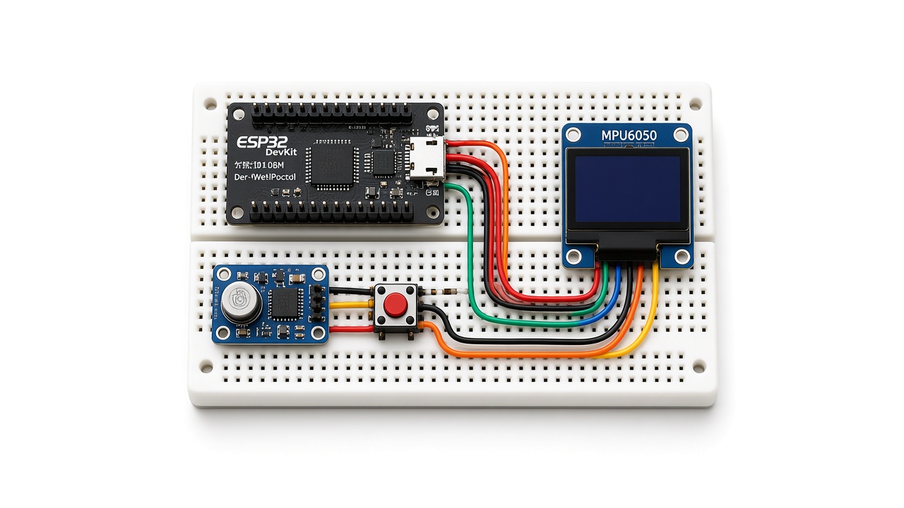
ESP32 Digital Spirit Level (Inclinometer) with MPU6050 and OLED Display

ESP32 digital spirit level on a breadboard with an MPU6050 sensor, OLED display and tare button

Build an ESP32 digital spirit level with an MPU6050 gyro/accelerometer and SSD1306 OLED: wiring table, tested code with complementary filter, tare button, troubleshooting and Hindi explanation.

  • DifficultyIntermediate
  • Build time2–4 hours
  • Board / MCUESP32 DevKit
  • Parts7 items
  • CodeArduino C++

Need it ready-made? Buy Ready Project

ESP32 digital spirit level on a breadboard with an MPU6050 sensor, OLED display and tare button

A digital spirit level (inclinometer) with ESP32, MPU6050 and an SSD1306 OLED is one of the most satisfying intermediate projects you can build in an evening. Instead of a glass tube with an air bubble, the ESP32 reads a 6-axis motion sensor, calculates the pitch and roll angles in degrees, and draws a “virtual bubble” on a 0.96-inch OLED screen. You get a readout accurate to a few tenths of a degree, a big LEVEL message when the surface is flat, and a push button that lets you zero the reading on any surface, which is handy for checking that a shelf matches the slope of an existing table, levelling a 3D-printer bed or setting the angle of a solar panel.

This tutorial gives you the complete parts list, a pin-to-pin wiring table, fully tested code (compile-checked for the ESP32 Dev Module board), a clear explanation of the complementary filter that keeps the reading stable, troubleshooting tips and an FAQ. A simple Hindi explanation is included for beginners. (यह प्रोजेक्ट हिंदी में भी समझाया गया है।)

How the Project Works

The MPU6050 contains a 3-axis accelerometer and a 3-axis gyroscope. When the sensor is still, the accelerometer measures only gravity, so simple trigonometry (atan2) tells us how far the board is tilted forward/backward (pitch) and left/right (roll). The problem is that the accelerometer is noisy and is disturbed by every small vibration. The gyroscope, on the other hand, measures rotation speed very smoothly, but if you integrate it over time it slowly drifts away from the true angle.

A complementary filter combines the best of both: every loop the angle is updated mostly (96%) from the gyroscope and corrected a little (4%) towards the accelerometer angle. The result is a smooth, fast and drift-free angle without any heavy maths like a Kalman filter. The ESP32 then draws the numbers and a moving bubble on the OLED. Both the MPU6050 and the OLED use the I2C bus, so they share the same two wires (SDA and SCL) with different addresses: 0x68 for the MPU6050 and 0x3C for the OLED.

Components Required

  • ESP32 DevKit V1 (ESP32-WROOM-32, 30 or 38 pin) – 1
  • MPU6050 module (GY-521) – 1
  • 0.96″ SSD1306 I2C OLED display, 128×64 (4-pin: VCC, GND, SCL, SDA) – 1
  • Tactile push button – 1 (used to zero/tare the angle)
  • Breadboard and male-to-male jumper wires
  • Micro-USB data cable
  • Optional: a small flat plastic box or 3D-printed case with a flat base, so the level sits flat on a surface

Wiring Table (Pin-to-Pin)

ModuleModule PinESP32 PinNotes
MPU6050 (GY-521)VCC3V3GY-521 has its own regulator; 3.3 V is safest for the I2C lines
MPU6050GNDGND
MPU6050SDAGPIO21I2C_SDA 21 in code
MPU6050SCLGPIO22I2C_SCL 22 in code
MPU6050AD0GND or not connectedKeeps address at 0x68
SSD1306 OLEDVCC3V3
SSD1306 OLEDGNDGND
SSD1306 OLEDSDAGPIO21Shared I2C bus
SSD1306 OLEDSCLGPIO22Shared I2C bus
Push buttonLeg 1GPIO4TARE_BUTTON 4, internal pull-up enabled
Push buttonLeg 2GNDPressed = LOW

Mount the MPU6050 flat on the breadboard and keep it firmly fixed. If the sensor wobbles on its header pins, the reading will wobble too. The X axis printed on the GY-521 board points “forward” for pitch in this code.

Libraries Used (with Licenses)

Complete ESP32 Code

Board used for the compile test: ESP32 Dev Module (Espressif Arduino core 3.x). The sketch compiled without errors.

// ESP32 Digital Inclinometer / Spirit Level
// MPU6050 + 0.96" SSD1306 I2C OLED + tare push button
// Libraries: Adafruit MPU6050, Adafruit Unified Sensor, Adafruit SSD1306, Adafruit GFX (all by Adafruit)
#include <Wire.h>
#include <Adafruit_MPU6050.h>
#include <Adafruit_Sensor.h>
#include <Adafruit_GFX.h>
#include <Adafruit_SSD1306.h>

#define I2C_SDA      21
#define I2C_SCL      22
#define TARE_BUTTON  4      // push button between GPIO4 and GND
#define SCREEN_W     128
#define SCREEN_H     64
#define OLED_ADDR    0x3C

Adafruit_MPU6050 mpu;
Adafruit_SSD1306 display(SCREEN_W, SCREEN_H, &Wire, -1);

float pitch = 0, roll = 0;            // filtered angles (degrees)
float pitchOffset = 0, rollOffset = 0; // set by the tare button
const float ALPHA = 0.96;              // complementary filter weight for the gyro
unsigned long lastMicros = 0;

void setup() {
  Serial.begin(115200);
  pinMode(TARE_BUTTON, INPUT_PULLUP);
  Wire.begin(I2C_SDA, I2C_SCL);

  if (!display.begin(SSD1306_SWITCHCAPVCC, OLED_ADDR)) {
    Serial.println("SSD1306 not found - check wiring/address");
    while (true) delay(1000);
  }
  display.clearDisplay();
  display.setTextColor(SSD1306_WHITE);
  display.setTextSize(1);
  display.setCursor(0, 0);
  display.println("ESP32 Inclinometer");
  display.display();

  if (!mpu.begin(0x68, &Wire)) {
    Serial.println("MPU6050 not found - check wiring");
    display.println("MPU6050 not found!");
    display.display();
    while (true) delay(1000);
  }
  mpu.setAccelerometerRange(MPU6050_RANGE_2_G);
  mpu.setGyroRange(MPU6050_RANGE_250_DEG);
  mpu.setFilterBandwidth(MPU6050_BAND_21_HZ);

  // start the filter from the accelerometer angle
  sensors_event_t a, g, t;
  mpu.getEvent(&a, &g, &t);
  pitch = atan2(-a.acceleration.x, sqrt(a.acceleration.y * a.acceleration.y + a.acceleration.z * a.acceleration.z)) * 180.0 / PI;
  roll  = atan2(a.acceleration.y, a.acceleration.z) * 180.0 / PI;
  lastMicros = micros();
  delay(500);
}

void drawLevel(float p, float r) {
  display.clearDisplay();
  display.setTextSize(1);
  display.setCursor(0, 0);
  display.print("Pitch:");
  display.print(p, 1);
  display.setCursor(0, 10);
  display.print("Roll :");
  display.print(r, 1);

  // bubble circle on the right side
  const int cx = 100, cy = 32, R = 28;
  display.drawCircle(cx, cy, R, SSD1306_WHITE);
  display.drawCircle(cx, cy, 6, SSD1306_WHITE);
  display.drawLine(cx - R, cy, cx + R, cy, SSD1306_WHITE);
  display.drawLine(cx, cy - R, cx, cy + R, SSD1306_WHITE);
  int bx = cx + (int)constrain(r * 2.0, -(R - 5), (R - 5));
  int by = cy + (int)constrain(p * 2.0, -(R - 5), (R - 5));
  display.fillCircle(bx, by, 4, SSD1306_WHITE);

  display.setCursor(0, 28);
  if (fabs(p) < 0.5 && fabs(r) < 0.5) {
    display.setTextSize(2);
    display.print("LEVEL");
  } else {
    display.print("Tilted");
  }
  display.setTextSize(1);
  display.setCursor(0, 54);
  display.print("BTN=Zero");
  display.display();
}

void loop() {
  sensors_event_t a, g, t;
  mpu.getEvent(&a, &g, &t);

  unsigned long now = micros();
  float dt = (now - lastMicros) / 1000000.0;
  lastMicros = now;

  // angles from gravity (accelerometer)
  float accPitch = atan2(-a.acceleration.x, sqrt(a.acceleration.y * a.acceleration.y + a.acceleration.z * a.acceleration.z)) * 180.0 / PI;
  float accRoll  = atan2(a.acceleration.y, a.acceleration.z) * 180.0 / PI;

  // gyro gives rad/s -> deg/s; complementary filter mixes both
  pitch = ALPHA * (pitch + g.gyro.y * 57.2958 * dt) + (1.0 - ALPHA) * accPitch;
  roll  = ALPHA * (roll  + g.gyro.x * 57.2958 * dt) + (1.0 - ALPHA) * accRoll;

  if (digitalRead(TARE_BUTTON) == LOW) {   // button pressed -> current position = zero
    pitchOffset = pitch;
    rollOffset = roll;
    delay(300);
  }

  float p = pitch - pitchOffset;
  float r = roll - rollOffset;

  static unsigned long lastDraw = 0;
  if (millis() - lastDraw > 100) {         // refresh screen 10 times per second
    lastDraw = millis();
    drawLevel(p, r);
    Serial.printf("Pitch: %.1f  Roll: %.1f\n", p, r);
  }
  delay(5);
}

Code Explanation

  • Wire.begin(21, 22) starts the I2C bus on the default ESP32 pins shared by both modules.
  • setAccelerometerRange(2G) gives the best resolution for tilt sensing, because gravity never exceeds 1 g when the level is still.
  • setFilterBandwidth(21 Hz) turns on the MPU6050’s internal low-pass filter to reduce vibration noise.
  • accPitch / accRoll are calculated from gravity with atan2() and converted from radians to degrees.
  • Complementary filter: pitch = 0.96 × (pitch + gyro × dt) + 0.04 × accPitch. The gyro value is in rad/s, so it is multiplied by 57.2958 to get degrees per second. dt is the real loop time measured with micros().
  • Tare button: pressing the button stores the current angles as offsets, so the display shows 0.0° on that surface.
  • drawLevel() prints both angles, draws a circle with cross-hairs, and moves a filled “bubble” 2 pixels per degree. When both angles are within ±0.5° the screen shows LEVEL.
  • The screen is refreshed 10 times per second; values are also printed to the Serial Monitor at 115200 baud.

Step-by-Step Build Instructions

  1. Install the ESP32 board package in Arduino IDE: File → Preferences, add https://espressif.github.io/arduino-esp32/package_esp32_index.json to Additional Boards Manager URLs, then install “esp32 by Espressif Systems” from Boards Manager.
  2. Open Library Manager and install Adafruit MPU6050. Accept the prompt to install its dependencies (Unified Sensor, BusIO). Then install Adafruit SSD1306 (it also pulls in Adafruit GFX).
  3. Place the ESP32 across the centre of the breadboard and connect its 3V3 and GND pins to the power rails.
  4. Wire the MPU6050 and the OLED to 3V3, GND, GPIO21 (SDA) and GPIO22 (SCL) exactly as in the wiring table.
  5. Connect the push button between GPIO4 and GND. No resistor is needed because the code enables the internal pull-up.
  6. Paste the code, choose ESP32 Dev Module and the correct COM port, then click Upload. If the upload stalls at “Connecting…”, hold the BOOT button for a second.
  7. Place the breadboard on a surface you know is level (or any surface) and press the button to zero the reading.
  8. Tilt the breadboard slowly: the bubble moves and the pitch/roll numbers change. When you return it to flat, “LEVEL” appears.
  9. For a practical tool, move the circuit into a small box with a flat, rigid base and power it from a USB power bank.

सरल हिंदी में समझें (Simple Hindi Explanation)

इस प्रोजेक्ट में ESP32 एक MPU6050 सेंसर से डेटा पढ़ता है। MPU6050 के अंदर accelerometer (गुरुत्व/ग्रैविटी की दिशा नापता है) और gyroscope (घूमने की गति नापता है) दोनों होते हैं। Accelerometer से हमें झुकाव का कोण (angle) मिलता है लेकिन उसमें थोड़ा शोर (noise) होता है, और gyroscope स्मूद होता है लेकिन धीरे-धीरे drift करता है। इसलिए हम complementary filter लगाते हैं – 96% gyroscope और 4% accelerometer मिलाकर एक स्थिर (stable) angle बनाते हैं।

यह angle OLED स्क्रीन पर नंबर और एक छोटे “बबल” के रूप में दिखता है, बिल्कुल असली स्पिरिट लेवल की तरह। जब सतह पूरी तरह समतल होती है तो स्क्रीन पर LEVEL लिखा आता है। GPIO4 वाला बटन दबाने पर मौजूदा स्थिति को “zero” मान लिया जाता है। दोनों मॉड्यूल I2C पर चलते हैं, इसलिए सिर्फ दो तार (SDA = GPIO21, SCL = GPIO22) से दोनों जुड़ जाते हैं।

Troubleshooting

ProblemFix
Serial Monitor shows “SSD1306 not found”Check SDA/SCL; some OLEDs use address 0x3D – change OLED_ADDR. Run an I2C scanner sketch to see the address.
“MPU6050 not found”Check VCC/GND; make sure AD0 is low (address 0x68). Re-seat the jumper wires – loose breadboard contacts are the usual cause.
Angle slowly driftsMake sure the board is still during start-up. A lower ALPHA (e.g. 0.92) corrects drift faster at the cost of a slightly noisier reading.
Reading jumps when the table is touchedThat is real vibration. Increase filtering: use MPU6050_BAND_10_HZ or average a few readings.
Pitch and roll seem swappedThe sensor is rotated 90° on your breadboard. Either rotate it or swap the two formulas.
Upload fails / “Failed to connect to ESP32”Hold BOOT while uploading, use a data (not charge-only) USB cable, and install the CP210x or CH340 driver.

Ideas to Extend the Project

  • Add a buzzer that beeps faster as you approach level, like a car parking sensor.
  • Serve the angle on a web page using the ESP32’s Wi-Fi for remote monitoring of a slope or a gate.
  • Log tilt of a wall, tree or pole over days to detect movement.
  • Mount it on a bicycle or RC car to log lean angles.

Frequently Asked Questions

How accurate is an MPU6050 spirit level?

After zeroing on a known flat surface, about ±0.2–0.5°, which is good enough for furniture, shelves and printer beds. For professional surveying you need a dedicated inclinometer sensor.

Can I use an Arduino Uno instead of the ESP32?

Yes. Connect SDA to A4 and SCL to A5, change Wire.begin(I2C_SDA, I2C_SCL) to Wire.begin() and replace Serial.printf with normal Serial.print calls. The Uno has enough memory for the SSD1306 buffer, but it is tight.

Why not just use the accelerometer?

The accelerometer alone is noisy and reacts to every bump. The gyroscope smooths the reading; the complementary filter gives a much steadier bubble.

Does the MPU6050 measure yaw (compass heading)?

Not reliably. Without a magnetometer, yaw from the gyroscope drifts over time. Pitch and roll are referenced to gravity, so they stay accurate.

Can I power it from a battery?

Yes – a USB power bank is easiest. You can also use a 3.7 V Li-ion cell with a TP4056 charger and a 3.3 V LDO regulator.

Related Projects

Browse more ESP32 Projects on Arduino Project Hub.

ESP32 DHT11 Weather Station with Web Server (Code + Wiring)

ESP32 board on a breadboard wired to a DHT11 sensor, with a phone showing the temperature and humidity web server dashboard – ESP32 DHT11 weather station

Build an ESP32 DHT11 weather station that shows live temperature and humidity on a web page. Wiring table, complete Arduino code and troubleshooting.

  • DifficultyEasy
  • Build time1–2 hours
  • Board / MCUESP32 DevKit
  • Parts5 items
  • CodeArduino C++

Need it ready-made? Buy Ready Project

In this project we build a Wi-Fi weather station with an ESP32 and a DHT11 sensor. The ESP32 reads temperature and humidity every two seconds and hosts its own web server, so you can open a live dashboard from any phone or laptop on the same Wi-Fi network – no cloud account, no app and no monthly fee. It also serves the readings as JSON at /data, which makes it easy to connect to Node-RED, Home Assistant or your own scripts later.

This is one of the best first IoT projects: it teaches sensor reading, Wi-Fi connection, HTML generation on a microcontroller and basic error handling, all in under 100 lines of code.

How It Works

The DHT11 contains a capacitive humidity element and a thermistor, plus a tiny chip that converts the readings into a digital signal on a single data wire. The ESP32 asks for a reading, the sensor answers with 40 bits of data, and the DHT library decodes it into °C and %RH. The ESP32 then joins your Wi-Fi as a station, gets an IP address from your router and listens on port 80. When a browser requests /, the sketch builds an HTML page containing the latest values; the page refreshes itself every 10 seconds.

Components Required

  • ESP32 DevKit V1 (ESP32-WROOM-32) – 1
  • DHT11 temperature & humidity sensor (3-pin module with built-in pull-up, or bare 4-pin sensor) – 1
  • 10 kΩ resistor – only if you use the bare 4-pin DHT11
  • Breadboard and jumper wires
  • USB data cable and a 2.4 GHz Wi-Fi network

Wiring Table (Pin-to-Pin)

DHT11 PinESP32 PinNotes
VCC (+)3V3DHT11 works from 3.3–5.5 V; 3.3 V keeps the data line ESP32-safe
DATA (OUT / S)GPIO4Matches #define DHTPIN 4
GND (−)GNDCommon ground
(bare sensor only) 10 kΩbetween DATA and 3V3Pull-up resistor; 3-pin modules already have it
(bare sensor only) pin 3not connectedNC pin

Libraries Used

  • DHT sensor library by Adafruit – adafruit/DHT-sensor-library (MIT license).
  • Adafruit Unified Sensor – required dependency – adafruit/Adafruit_Sensor (Apache-2.0).
  • WiFi.h and WebServer.h come with the ESP32 Arduino core: espressif/arduino-esp32 (LGPL-2.1).
  • The sketch itself is original code written for this tutorial; the DHT read pattern follows the library’s DHTtester example.

Complete Code

// ESP32 DHT11 Weather Station with Web Server
// Libraries: "DHT sensor library" + "Adafruit Unified Sensor" (Adafruit)
// Board: ESP32 Dev Module
#include <WiFi.h>
#include <WebServer.h>
#include <DHT.h>

const char* ssid     = "YOUR_WIFI_SSID";
const char* password = "YOUR_WIFI_PASSWORD";

#define DHTPIN  4        // DHT11 DATA -> GPIO4
#define DHTTYPE DHT11    // change to DHT22 if you use a DHT22
DHT dht(DHTPIN, DHTTYPE);
WebServer server(80);

float temperature = NAN, humidity = NAN;
unsigned long lastRead = 0;

void readSensor() {
  float h = dht.readHumidity();
  float t = dht.readTemperature();   // Celsius
  if (isnan(h) || isnan(t)) {
    Serial.println("Failed to read from DHT sensor!");
    return;                          // keep last good values
  }
  humidity = h;
  temperature = t;
  Serial.printf("Temp: %.1f C  Humidity: %.1f %%\n", t, h);
}

String valueOrDash(float v) { return isnan(v) ? String("--") : String(v, 1); }

void handleRoot() {
  String html = "<!DOCTYPE html><html><head><meta charset='utf-8'>"
                "<meta name='viewport' content='width=device-width,initial-scale=1'>"
                "<meta http-equiv='refresh' content='10'>"
                "<title>ESP32 Weather Station</title>"
                "<style>body{font-family:Arial;text-align:center;background:#0f172a;color:#fff}"
                ".card{display:inline-block;margin:12px;padding:20px 30px;border-radius:12px;background:#1e293b}"
                ".v{font-size:2.5em;color:#22c55e}</style></head><body>"
                "<h1>ESP32 Weather Station</h1>";
  html += "<div class='card'><div>Temperature</div><div class='v'>" + valueOrDash(temperature) + " &deg;C</div></div>";
  html += "<div class='card'><div>Humidity</div><div class='v'>" + valueOrDash(humidity) + " %</div></div>";
  html += "<p>Auto-refresh every 10 s</p></body></html>";
  server.send(200, "text/html", html);
}

void handleJson() {
  String json = "{\"temperature\":" + valueOrDash(temperature) +
                ",\"humidity\":" + valueOrDash(humidity) + "}";
  if (isnan(temperature)) json = "{\"error\":\"sensor not ready\"}";
  server.send(200, "application/json", json);
}

void setup() {
  Serial.begin(115200);
  dht.begin();
  WiFi.mode(WIFI_STA);
  WiFi.begin(ssid, password);
  Serial.print("Connecting to WiFi");
  while (WiFi.status() != WL_CONNECTED) { delay(500); Serial.print("."); }
  Serial.print("\nConnected! Open http://");
  Serial.println(WiFi.localIP());
  server.on("/", handleRoot);
  server.on("/data", handleJson);
  server.begin();
  readSensor();
}

void loop() {
  server.handleClient();
  if (millis() - lastRead > 2000) {   // DHT11: max 1 reading per second
    lastRead = millis();
    readSensor();
  }
}

Code Explanation

  • Credentials: replace YOUR_WIFI_SSID and YOUR_WIFI_PASSWORD. The ESP32 only supports 2.4 GHz networks.
  • readSensor() reads humidity and temperature. If either value is NAN (failed read), the old values are kept, so the web page never shows garbage.
  • Non-blocking timing: instead of delay(2000), the loop uses millis(), so the web server keeps answering requests instantly.
  • handleRoot() builds a mobile-friendly HTML page with two cards; meta refresh reloads it every 10 seconds.
  • handleJson() returns {"temperature":27.0,"humidity":61.0} for other apps.

Step-by-Step Instructions

  1. Install the ESP32 board package (Boards Manager → “esp32” by Espressif).
  2. Install “DHT sensor library” and “Adafruit Unified Sensor” from Library Manager.
  3. Wire the DHT11 exactly as in the table: VCC → 3V3, DATA → GPIO4, GND → GND.
  4. Paste the code and enter your Wi-Fi name and password.
  5. Select ESP32 Dev Module and the correct port, then Upload (hold BOOT if it is stuck at “Connecting…”).
  6. Open Serial Monitor at 115200 baud. After “Connected!” note the IP address, e.g. 192.168.1.45.
  7. On your phone (same Wi-Fi) open http://192.168.1.45. You will see live temperature and humidity.
  8. Breathe gently on the sensor – humidity should rise within a few seconds, which confirms everything works.

Troubleshooting

ProblemFix
“Failed to read from DHT sensor!”Check DATA is on GPIO4, add the 10 kΩ pull-up for bare sensors, make sure DHTTYPE matches your sensor (DHT11 vs DHT22).
Stuck on “Connecting to WiFi…..”Check SSID/password spelling, use a 2.4 GHz network, move closer to the router.
Page does not openPhone must be on the same network; type http:// not https; check the IP in Serial Monitor.
Temperature reads 1–2 °C highThe ESP32 warms up; keep the sensor a few cm away from the board.
Compile error “Adafruit_Sensor.h not found”Install the Adafruit Unified Sensor library.

Upgrade Ideas

  • Swap to a DHT22 or BME280 for better accuracy (and pressure on BME280).
  • Log data to ThingSpeak or Google Sheets for graphs.
  • Add an OLED display for a standalone readout.
  • Use deep sleep and a battery for an outdoor station.

Frequently Asked Questions

DHT11 vs DHT22 – which is better?

DHT11 measures 0–50 °C (±2 °C) and 20–80 % RH (±5 %). DHT22 covers −40–80 °C (±0.5 °C) and 0–100 % RH (±2–5 %). For a few rupees more, DHT22 is more accurate; just change DHTTYPE to DHT22.

Can I view it from outside my home?

Not directly; the server is on your local network. Use port forwarding (not recommended), a VPN, or a cloud service such as Blynk, ThingSpeak or MQTT.

Why read only every 2 seconds?

The DHT11 cannot be read faster than about once per second; faster reads return errors.

Does it work with ESP8266?

Yes – replace WiFi.h/WebServer.h with ESP8266WiFi.h/ESP8266WebServer.h, use ESP8266WebServer server(80);, and connect DATA to D2 (GPIO4).

Related Projects

Browse more ESP32 Projects on Arduino Project Hub.

Heart and Pulse Monitoring System using ESP32 and Pulse Sensor

ESP32 heart-rate and pulse monitoring project on a breadboard with an OLED display and an optical pulse sensor

आज के समय में health monitoring हर घर की ज़रूरत बन चुकी है। In this tutorial we build a heart rate and pulse monitoring system using an ESP32, a low-cost optical pulse sensor and a 0.96-inch SSD1306 OLED display. The device detects every heartbeat from your fingertip, calculates beats per minute (BPM), shows it on … Read more

  • DifficultyIntermediate
  • Build time2–4 hours
  • Board / MCUESP32 DevKit
  • Parts6 items
  • CodeArduino C++

Need it ready-made? Buy Ready Project

ESP32 heart-rate and pulse monitoring project on a breadboard with an OLED display and an optical pulse sensor

आज के समय में health monitoring हर घर की ज़रूरत बन चुकी है। In this tutorial we build a heart rate and pulse monitoring system using an ESP32, a low-cost optical pulse sensor and a 0.96-inch SSD1306 OLED display. The device detects every heartbeat from your fingertip, calculates beats per minute (BPM), shows it on the OLED, blinks an LED on each beat and prints the live signal to the Serial Plotter. You get the full components list, a pin-to-pin wiring table, complete working code, step-by-step instructions, troubleshooting tips and an FAQ.

Important: this is an educational hobby project, not a medical device. Do not use it to diagnose or treat any health condition. Also note: a BMP180 is a barometric (air) pressure sensor and cannot measure blood pressure. Real blood pressure measurement needs an inflatable cuff and a calibrated pressure transducer, so this tutorial focuses on heart rate only.

How the Pulse Sensor Works

The common “Pulse Sensor” module (green LED plus ambient light photo-sensor) works on photoplethysmography (PPG). The green LED shines into your fingertip, and the photo-sensor measures how much light is reflected back. Every time your heart pumps, the volume of blood in the capillaries rises for a moment, which changes the reflected light. The module amplifies this into an analog voltage that rises and falls with each heartbeat.

The ESP32 samples this voltage about 100 times per second with its 12-bit ADC (values 0 to 4095). When the signal crosses a threshold on the way up, we count a beat. The time between two beats is the inter-beat interval (IBI) in milliseconds, and the heart rate is simply BPM = 60000 / IBI. To make the number stable, the code uses a running average and ignores intervals that are physically impossible (faster than 200 BPM or slower than 30 BPM).

Components Required

  • ESP32 development board (ESP32-WROOM-32 DevKit V1 or similar) – 1
  • Pulse Sensor module (analog, 3-pin: +, −, S) – 1
  • 0.96-inch SSD1306 OLED display, 128×64, I2C (4-pin: VCC, GND, SCL, SDA) – 1
  • Breadboard and male-to-male / male-to-female jumper wires
  • Micro-USB (or USB-C) data cable
  • Optional: Velcro strap or the ear clip supplied with the sensor for steady contact

Circuit Diagram / Wiring Table (Pin-to-Pin)

Both modules run on 3.3 V, which keeps the pulse sensor output inside the ESP32 ADC range (never feed more than 3.3 V into an ESP32 pin). GPIO34 is used because it is on ADC1, which keeps working when Wi-Fi is on (ADC2 pins do not).

ModuleModule PinESP32 PinNotes
Pulse Sensor+ (VCC, red)3V3Power at 3.3 V only
Pulse Sensor− (GND, black)GNDCommon ground
Pulse SensorS (Signal, purple)GPIO34Analog input (ADC1_CH6)
OLED SSD1306VCC3V3
OLED SSD1306GNDGND
OLED SSD1306SDAGPIO21Default I2C SDA
OLED SSD1306SCLGPIO22Default I2C SCL
On-board LED—GPIO2Built into most DevKit boards

Libraries and Board Setup

  • Install the ESP32 board package by Espressif: in Arduino IDE open File → Preferences, add https://espressif.github.io/arduino-esp32/package_esp32_index.json to Additional Boards Manager URLs, then install “esp32” from Boards Manager. (Source: espressif/arduino-esp32, LGPL-2.1.)
  • Adafruit SSD1306 – OLED driver (GitHub, BSD license).
  • Adafruit GFX Library – graphics/text functions used by the SSD1306 library (GitHub, BSD license).
  • Wire.h is built into the ESP32 core. The beat-detection logic below is original code written for this tutorial, so no pulse-sensor library is needed.

Complete Arduino Code

// Heart Rate (BPM) Monitor - ESP32 + Pulse Sensor + SSD1306 OLED
// Libraries: Adafruit SSD1306, Adafruit GFX (install from Library Manager)
// Board: "ESP32 Dev Module" (Espressif ESP32 Arduino core)
#include <Wire.h>
#include <Adafruit_GFX.h>
#include <Adafruit_SSD1306.h>

#define SCREEN_WIDTH 128
#define SCREEN_HEIGHT 64
Adafruit_SSD1306 display(SCREEN_WIDTH, SCREEN_HEIGHT, &Wire, -1);

const int PULSE_PIN = 34;   // Pulse sensor signal (ADC1, input-only pin)
const int LED_PIN   = 2;    // On-board LED blinks on every beat
int threshold = 2200;       // 12-bit ADC (0-4095); tune using Serial Plotter
const int HYSTERESIS = 100;

unsigned long lastBeat = 0;
bool aboveThreshold = false;
float bpmAvg = 0;

void setup() {
  Serial.begin(115200);
  pinMode(LED_PIN, OUTPUT);
  analogReadResolution(12);
  Wire.begin(21, 22);  // SDA, SCL
  if (!display.begin(SSD1306_SWITCHCAPVCC, 0x3C)) {
    Serial.println("SSD1306 not found - check wiring/address");
    while (true) delay(10);
  }
  display.clearDisplay();
  display.setTextColor(SSD1306_WHITE);
  display.setTextSize(1);
  display.setCursor(0, 0);
  display.println("Place your finger");
  display.println("on the sensor...");
  display.display();
}

void loop() {
  int signal = analogRead(PULSE_PIN);
  unsigned long now = millis();

  // Rising edge = heartbeat
  if (signal > threshold && !aboveThreshold) {
    aboveThreshold = true;
    unsigned long ibi = now - lastBeat;          // inter-beat interval (ms)
    if (lastBeat == 0 || ibi > 300) {            // ignore noise (>200 BPM)
      if (lastBeat > 0 && ibi < 2000) {          // valid range 30-200 BPM
        float bpm = 60000.0 / ibi;
        bpmAvg = (bpmAvg == 0) ? bpm : (bpmAvg * 0.8 + bpm * 0.2);
      }
      lastBeat = now;
      digitalWrite(LED_PIN, HIGH);
    }
  }
  if (signal < threshold - HYSTERESIS && aboveThreshold) {
    aboveThreshold = false;
    digitalWrite(LED_PIN, LOW);
  }
  if (lastBeat > 0 && now - lastBeat > 3000) bpmAvg = 0;  // finger removed

  static unsigned long lastDraw = 0;
  if (now - lastDraw > 500) {
    lastDraw = now;
    display.clearDisplay();
    display.setTextSize(1);
    display.setCursor(0, 0);
    display.println("Heart Rate Monitor");
    display.setTextSize(3);
    display.setCursor(0, 22);
    if (bpmAvg > 0) {
      display.print((int)bpmAvg);
      display.setTextSize(1);
      display.print(" BPM");
    } else {
      display.setTextSize(1);
      display.print("No pulse detected");
    }
    display.display();
    Serial.printf("Signal:%d BPM:%.0f\n", signal, bpmAvg);
  }
  delay(10);  // ~100 samples per second
}

Code Explanation

  • analogReadResolution(12) sets the ADC to 0–4095, so the idle signal sits roughly around 1800–2100 and peaks rise above it.
  • Threshold with hysteresis: a beat is counted when the signal goes above threshold; the next beat can only be counted after the signal drops 100 points below it. This stops one noisy peak from being counted twice.
  • IBI filter: intervals shorter than 300 ms (above 200 BPM) are ignored as noise, and intervals longer than 2 seconds are not used for BPM.
  • Running average: bpmAvg = bpmAvg*0.8 + bpm*0.2 smooths the display so the number does not jump on every beat.
  • Finger removed: if no beat is detected for 3 seconds the BPM resets and the OLED shows “No pulse detected”.
  • The OLED refreshes every 500 ms; drawing more often would slow down sampling.

Step-by-Step Instructions

  1. Place the ESP32 across the middle of the breadboard so both pin rows are free.
  2. Connect the 3V3 and GND pins of the ESP32 to the breadboard power rails.
  3. Wire the pulse sensor: + to 3V3, − to GND, S to GPIO34.
  4. Wire the OLED: VCC to 3V3, GND to GND, SDA to GPIO21, SCL to GPIO22.
  5. Install the ESP32 board package and the two Adafruit libraries listed above.
  6. Open Arduino IDE, select Tools → Board → ESP32 Dev Module and the correct COM port.
  7. Paste the code, click Upload. If upload hangs at “Connecting…”, hold the BOOT button on the ESP32 until it starts writing.
  8. Open Tools → Serial Plotter at 115200 baud. Rest your fingertip lightly on the sensor (do not press hard) and watch the waveform.
  9. Note the typical peak value and the resting value, and set threshold to roughly halfway between them. Upload again.
  10. Keep your hand still for 10–15 seconds; the OLED will show a stable BPM. Compare it with counting your pulse at the wrist for 60 seconds.

Troubleshooting

ProblemLikely CauseFix
OLED stays blank / “SSD1306 not found”Wrong I2C address or SDA/SCL swappedMost modules use 0x3C; some use 0x3D. Run an I2C scanner sketch and check wiring.
BPM always 0Threshold too high or poor finger contactCheck Serial Plotter, lower threshold, cover the sensor from room light.
BPM too high (150+ while resting)Noise counted as beatsRaise threshold or HYSTERESIS; keep the finger still; use a short ground wire.
Signal flat at 0 or 4095Wrong pin or sensor powered at 5 VUse GPIO34 and power the sensor from 3V3.
Readings unstable with Wi-Fi added laterUsing an ADC2 pinStay on ADC1 pins (GPIO32–39).
Upload failsCharge-only USB cable or missing driverUse a data cable; install CP210x or CH340 USB driver.

Ideas to Extend This Project

  • Send BPM to a phone dashboard (Blynk, ThingSpeak or a simple ESP32 web server).
  • Upgrade to a MAX30102 sensor to measure both heart rate and SpO2 (blood oxygen) over I2C.
  • Add a buzzer that beeps on every beat, or an alert when BPM goes outside a set range.
  • Log readings to an SD card or Google Sheets for daily tracking.

Frequently Asked Questions

Can this project measure blood pressure?

No. Blood pressure needs a cuff and a calibrated pressure sensor. The BMP180 or BMP280 measures air pressure, not blood pressure. This project measures heart rate (BPM) only.

Can I use Arduino Uno instead of ESP32?

Yes. Connect the signal to A0, power the sensor at 5 V, use pins A4 (SDA) and A5 (SCL) for the OLED, remove Wire.begin(21, 22) and analogReadResolution(12), and change the threshold to around 550 because the Uno ADC is 10-bit (0–1023).

Why does my reading change when I press harder?

Pressing too hard squeezes blood out of the fingertip and weakens the signal. Rest the finger lightly, or use the ear clip.

How accurate is it?

With a still finger and a tuned threshold it is usually within a few BPM of a manual count, but it is not a certified medical instrument.

Which pins can I use for the sensor?

Any ADC1 pin: GPIO32, 33, 34, 35, 36 or 39. Update PULSE_PIN in the code if you change it.

Related Projects

Browse more ESP32 Projects on Arduino Project Hub.