
Build an STM32 Blue Pill thermometer with a DS18B20 sensor, SSD1306 OLED and a high-temperature buzzer alarm. Includes wiring table, diagram and full code.
Need it ready-made? Buy Ready Project
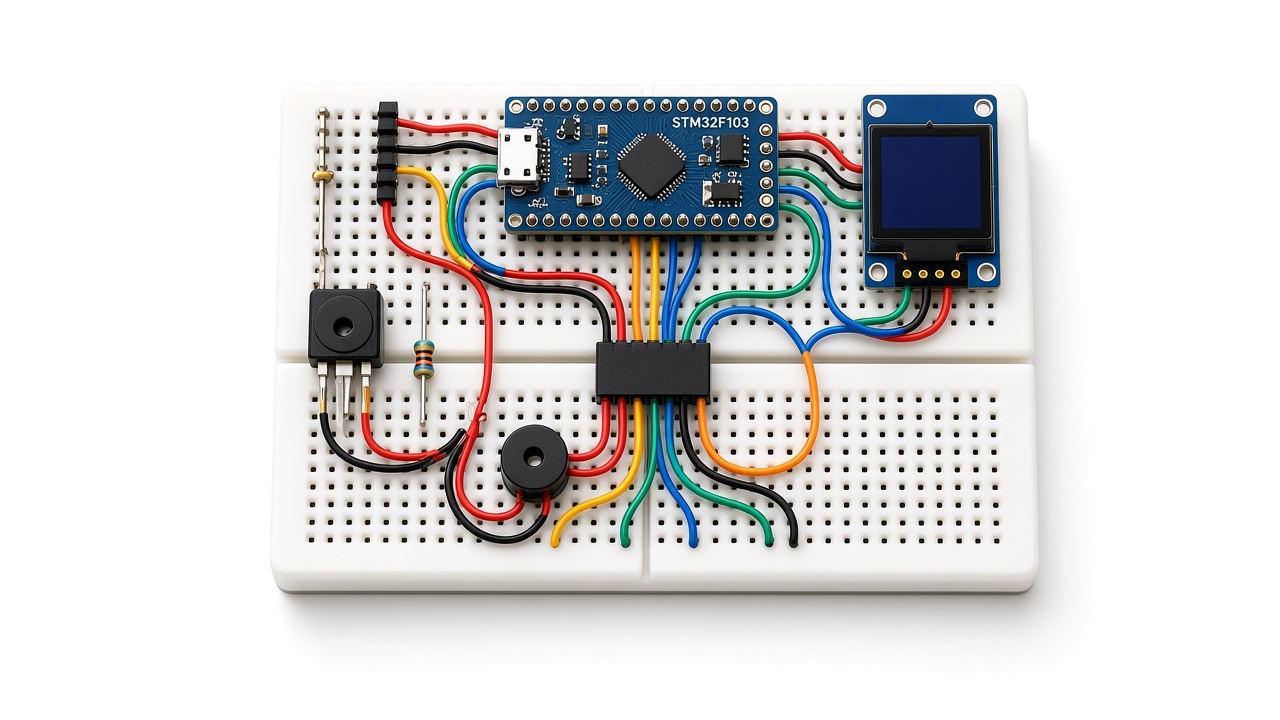
This STM32 Blue Pill thermometer reads a DS18B20 digital temperature sensor, shows the live reading with the minimum and maximum values on a 0.96 inch SSD1306 OLED, and sounds a buzzer when the temperature goes above a limit you set. It is a good step up from Arduino boards: the STM32F103C8T6 runs at 72 MHz, has 64 KB of flash, and you can still program it from the Arduino IDE using the official STM32duino core.
Use it as a fridge or freezer monitor, an aquarium thermometer, a 3D-printer enclosure alarm, or a soldering-room temperature display. The waterproof DS18B20 probe can sit in liquid while the Blue Pill and OLED stay dry. Below you get the parts list, a pin-to-pin wiring table, a connection diagram, upload steps with an ST-Link, and fully commented code.
How the STM32 Blue Pill Thermometer Works
The DS18B20 talks over the 1-Wire bus, which needs only one data pin. Here the data line goes to PA1 with a 4.7 kΩ pull-up resistor to 3.3 V. Every second the Blue Pill asks the sensor to start a 12-bit conversion (0.0625 °C steps, about 750 ms), then reads back the result in degrees Celsius. If the sensor does not answer, the library returns −127 °C and the code shows a sensor error instead of a fake reading.
The OLED uses I2C1 on PB6 (SCL) and PB7 (SDA), the default pins for Wire in the STM32duino core. The screen shows the current temperature in large digits, the minimum and maximum since power-up, and the alarm limit. When the reading reaches the limit (40 °C by default), PB12 goes HIGH, switches on a 2N2222 transistor and the active buzzer sounds. The alarm turns off only after the temperature falls 1 °C below the limit. This small gap, called hysteresis, stops the buzzer from chattering on and off right at the threshold.
The Blue Pill is a 3.3 V board. The DS18B20 and the OLED both run happily at 3.3 V, so no level shifting is needed. The buzzer is powered from the board’s 5 V pin (USB power) through the transistor, so the GPIO pin never has to supply the buzzer current.
Components Required
- STM32F103C8T6 Blue Pill board – 1
- ST-Link V2 programmer (or a USB-to-serial adapter for the serial bootloader) – 1
- DS18B20 temperature sensor, waterproof probe or TO-92 – 1
- 4.7 kΩ resistor – 1 (1-Wire pull-up)
- 0.96 inch SSD1306 128×64 I2C OLED module – 1
- 5 V active buzzer – 1
- 2N2222 (or BC547) NPN transistor – 1
- 1 kΩ resistor – 1 (transistor base)
- Breadboard and jumper wires
- Micro-USB cable for 5 V power
Wiring Table (Pin-to-Pin)
| Module | Module Pin | Blue Pill Pin | Notes |
|---|---|---|---|
| DS18B20 | VDD (red) | 3.3V | Do not use parasite power mode for this build |
| DS18B20 | GND (black) | GND | Common ground |
| DS18B20 | DATA (yellow) | PA1 | Add a 4.7 kΩ resistor from PA1 to 3.3V |
| SSD1306 OLED | VCC | 3.3V | Most modules accept 3.3–5 V |
| SSD1306 OLED | GND | GND | Common ground |
| SSD1306 OLED | SCL | PB6 | I2C1 clock, default Wire pin |
| SSD1306 OLED | SDA | PB7 | I2C1 data, default Wire pin |
| 2N2222 | Base | PB12 | Through a 1 kΩ resistor |
| 2N2222 | Emitter | GND | Common ground |
| 2N2222 | Collector | Buzzer (−) | Transistor switches the buzzer’s negative side |
| Active buzzer | + | 5V | From the Blue Pill 5V pin (USB power) |
| ST-Link V2 | SWDIO / SWCLK / 3.3V / GND | PA13 / PA14 / 3.3V / GND | For uploading only. Keep USB unplugged while the ST-Link powers the board |
Check the pin labels printed on your own Blue Pill. Clones vary, but PA1, PB6, PB7, PB12 and the 3.3V, 5V and GND pins are on every version. If your buzzer is a passive type (no internal oscillator), it will only click, so use an active buzzer or change the code to use tone().
Connection Diagram
Setting Up the Arduino IDE for STM32
- In the Arduino IDE, open File > Preferences and add the STM32duino board manager URL:
https://github.com/stm32duino/BoardManagerFiles/raw/main/package_stmicroelectronics_index.json - Open Tools > Board > Boards Manager, search for STM32 MCU based boards by STMicroelectronics and install it.
- Select Generic STM32F1 series as the board and BluePill F103C8 as the board part number.
- Set Upload method to STM32CubeProgrammer (SWD) if you use an ST-Link. Install STM32CubeProgrammer from ST so the IDE can find it.
- Install these libraries from the Library Manager: OneWire, DallasTemperature, Adafruit GFX Library and Adafruit SSD1306.
- Connect the ST-Link to SWDIO, SWCLK, 3.3V and GND, then click Upload.
If you want serial output on the USB port, set USB support to CDC (generic Serial supersede U(S)ART) in the Tools menu. Otherwise Serial goes to PA9 (TX) and PA10 (RX), which you can read with a USB-to-serial adapter.
Code
The full sketch is below. Change ALARM_HIGH_C to set your own alarm temperature, and change OLED_ADDRESS to 0x3D if your display does not start.
/*
  STM32 Blue Pill DS18B20 Thermometer with OLED & Alarm
  -----------------------------------------------------
  Board  : STM32F103C8T6 "Blue Pill" (STM32duino core by STMicroelectronics)
  Sensor : DS18B20 (1-Wire) on PA1 with a 4.7 kOhm pull-up to 3.3 V
  Display: 0.96" SSD1306 128x64 I2C OLED on I2C1 (PB6 = SCL, PB7 = SDA)
  Alarm  : Active buzzer switched by a 2N2222 NPN transistor from PB12
  LED    : On-board LED on PC13 (active LOW) blinks on each reading

  Libraries (Arduino Library Manager):
    - OneWire
    - DallasTemperature
    - Adafruit GFX Library
    - Adafruit SSD1306
*/

#include <Wire.h>
#include <OneWire.h>
#include <DallasTemperature.h>
#include <Adafruit_GFX.h>
#include <Adafruit_SSD1306.h>

// ---------- Pin definitions ----------
#define ONE_WIRE_PIN   PA1    // DS18B20 data line
#define BUZZER_PIN     PB12   // Drives the 2N2222 base through 1 kOhm
#define LED_PIN        PC13   // On-board LED (LOW = ON)

// ---------- OLED settings ----------
#define SCREEN_WIDTH   128
#define SCREEN_HEIGHT  64
#define OLED_RESET     -1     // Module has no reset pin wired
#define OLED_ADDRESS   0x3C   // Use 0x3D if your module is set to that

// ---------- Alarm settings ----------
const float ALARM_HIGH_C   = 40.0;  // Buzzer turns ON above this temperature
const float ALARM_HYST_C   = 1.0;   // Turns OFF only after falling 1 C below the limit
const unsigned long READ_INTERVAL_MS = 1000;  // One reading per second

OneWire oneWire(ONE_WIRE_PIN);
DallasTemperature sensors(&oneWire);
Adafruit_SSD1306 display(SCREEN_WIDTH, SCREEN_HEIGHT, &Wire, OLED_RESET);

float minTempC = 1000.0;    // Lowest temperature seen since power-up
float maxTempC = -1000.0;   // Highest temperature seen since power-up
bool  alarmOn  = false;
unsigned long lastReadMs = 0;

void showMessage(const char *line1, const char *line2) {
  display.clearDisplay();
  display.setTextSize(1);
  display.setTextColor(SSD1306_WHITE);
  display.setCursor(0, 20);
  display.println(line1);
  display.println(line2);
  display.display();
}

void setup() {
  Serial.begin(115200);

  pinMode(BUZZER_PIN, OUTPUT);
  digitalWrite(BUZZER_PIN, LOW);     // Buzzer off at start
  pinMode(LED_PIN, OUTPUT);
  digitalWrite(LED_PIN, HIGH);       // On-board LED off (active LOW)

  // Default STM32duino I2C pins for Wire are PB7 (SDA) and PB6 (SCL)
  Wire.begin();

  if (!display.begin(SSD1306_SWITCHCAPVCC, OLED_ADDRESS)) {
    // OLED not found: blink the LED fast forever so the fault is visible
    while (true) {
      digitalWrite(LED_PIN, !digitalRead(LED_PIN));
      delay(100);
    }
  }

  showMessage("STM32 Thermometer", "Starting DS18B20...");

  sensors.begin();
  sensors.setResolution(12);          // 12-bit = 0.0625 C steps, ~750 ms conversion
  sensors.setWaitForConversion(true); // Simple blocking read once per second

  if (sensors.getDeviceCount() == 0) {
    showMessage("DS18B20 not found!", "Check PA1 + 4.7k pull-up");
    Serial.println("No DS18B20 found on PA1");
  }
  delay(1000);
}

void loop() {
  if (millis() - lastReadMs < READ_INTERVAL_MS) return;
  lastReadMs = millis();

  sensors.requestTemperatures();
  float tempC = sensors.getTempCByIndex(0);

  // DEVICE_DISCONNECTED_C (-127) means the sensor did not answer
  if (tempC == DEVICE_DISCONNECTED_C) {
    digitalWrite(BUZZER_PIN, LOW);
    showMessage("Sensor error", "Check DS18B20 wiring");
    Serial.println("Sensor error");
    return;
  }

  // Track min / max since power-up
  if (tempC < minTempC) minTempC = tempC;
  if (tempC > maxTempC) maxTempC = tempC;

  // Alarm with hysteresis so the buzzer does not chatter at the limit
  if (!alarmOn && tempC >= ALARM_HIGH_C) alarmOn = true;
  if (alarmOn && tempC <= ALARM_HIGH_C - ALARM_HYST_C) alarmOn = false;
  digitalWrite(BUZZER_PIN, alarmOn ? HIGH : LOW);

  // ---------- Draw the screen ----------
  display.clearDisplay();
  display.setTextColor(SSD1306_WHITE);

  display.setTextSize(1);
  display.setCursor(0, 0);
  display.print("Temperature");
  if (alarmOn) {
    display.setCursor(86, 0);
    display.print("ALARM!");
  }

  display.setTextSize(3);             // Big main reading
  display.setCursor(0, 16);
  display.print(tempC, 1);
  display.setTextSize(2);
  display.print(" C");

  display.setTextSize(1);
  display.setCursor(0, 46);
  display.print("Min:");
  display.print(minTempC, 1);
  display.print("  Max:");
  display.print(maxTempC, 1);

  display.setCursor(0, 56);
  display.print("Limit: ");
  display.print(ALARM_HIGH_C, 1);
  display.print(" C");
  display.display();

  // Serial log for the Arduino Serial Monitor / Plotter
  Serial.print("Temp C: ");
  Serial.print(tempC, 2);
  Serial.print("  Min: ");
  Serial.print(minTempC, 2);
  Serial.print("  Max: ");
  Serial.print(maxTempC, 2);
  Serial.println(alarmOn ? "  ALARM" : "");

  // Short blink of the on-board LED to show the loop is alive
  digitalWrite(LED_PIN, LOW);
  delay(30);
  digitalWrite(LED_PIN, HIGH);
}
Testing the Thermometer
- Power the Blue Pill from USB. The OLED should show the start-up message, then the temperature within two seconds.
- Hold the DS18B20 in your hand. The reading should rise by a few degrees and the Max value should follow it.
- Set
ALARM_HIGH_Cto a value just above room temperature (for example 30.0), upload again, and warm the sensor. The buzzer should sound and the screen should show ALARM! - Let the sensor cool. The buzzer turns off once the reading is 1 °C below the limit.
Troubleshooting
| Problem | Fix |
|---|---|
| Screen shows “DS18B20 not found” or reads −127 °C | Check the 4.7 kΩ pull-up from PA1 to 3.3V and make sure the sensor’s DATA wire really goes to PA1. Some probes use a different wire colour, so check its datasheet. |
| OLED stays blank and the on-board LED blinks fast | The display was not found. Swap SDA and SCL if they are reversed, check 3.3V and GND, or change OLED_ADDRESS to 0x3D. |
| Upload fails with “No STM32 target found” | Check SWDIO and SWCLK, share ground with the ST-Link, and try holding the RESET button while you click Upload and releasing it when the upload starts. |
| Buzzer never sounds | Confirm it is an active buzzer, its + leg goes to 5V, and the transistor’s emitter goes to GND. Measure about 0.7 V on the base when the alarm is on. |
| Reading jumps around | Use a short, twisted cable for long probes, keep the pull-up close to the Blue Pill, and power the sensor from 3.3V, not parasite mode. |
Ideas to Extend This Project
- Add a second DS18B20 on the same PA1 wire and show two temperatures, for example fridge and freezer.
- Add two push buttons to change the alarm limit without re-uploading the code.
- Log readings to a microSD card over SPI for a temperature data logger.
- Add a low-temperature alarm as well as the high one for freezer or incubator use.
FAQ
Can I power the DS18B20 from 5 V on the Blue Pill? Keep it on 3.3V. The pull-up then holds the data line at 3.3V, which is safe for PA1. Many STM32 pins are 5 V tolerant, but there is no reason to take the risk here.
Does this code work on the Black Pill (STM32F401/F411)? Yes, with the matching board selected in the STM32duino core. Check that PB6, PB7 and PB12 are free on your board, or change the pin numbers at the top of the sketch.
How accurate is the DS18B20? The datasheet rates it at ±0.5 °C from −10 °C to +85 °C, which is fine for fridges, rooms, aquariums and enclosures.
Related Projects
- ESP32 DHT11 Weather Station with Web Server
- ATmega16 Temperature Controller with LM35
- Raspberry Pi Pico Digital Weighing Scale with HX711
- ESP32 Digital Spirit Level with MPU6050
Browse more Sensors on Arduino Project Hub.