
Build a long-range LoRa GPS tracker with two ESP32 boards, Ra-02 SX1278 modules and a NEO-6M GPS. Wiring tables, two tested sketches, OLED receiver with RSSI, range tips and Hindi explanation.
Need it ready-made? Buy Ready Project
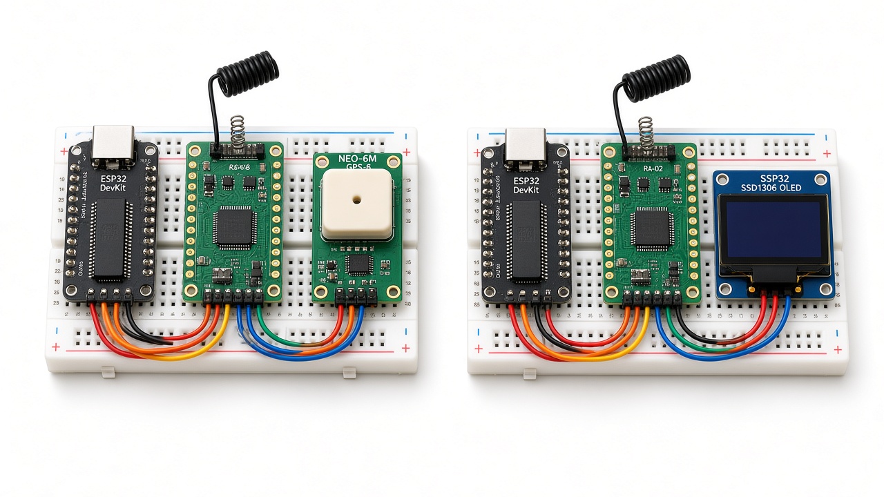
Wi-Fi reaches a few tens of metres and mobile data needs a SIM card and a monthly plan. LoRa (Long Range) radio can send small packets over several kilometres with no network, no SIM and very little power. In this intermediate project we combine LoRa with GPS to build a LoRa GPS tracker using two ESP32 boards, Ra-02 (SX1278) modules and a NEO-6M GPS. The transmitter reads its position from the GPS every 5 seconds and broadcasts it by LoRa; the receiver shows latitude, longitude, speed, number of satellites and signal strength (RSSI/SNR) on an OLED display and prints a Google Maps link on the Serial Monitor.
It is a great project for tracking a bicycle, a pet, a drone, a farm vehicle or a hiking partner in an area without mobile coverage. Below you will find the parts list, wiring tables for both nodes, two compile-tested sketches, a detailed explanation, step-by-step build, range tips, troubleshooting, FAQ and a simple Hindi explanation.
How the System Works
The NEO-6M GPS module continuously outputs NMEA sentences (text like $GPGGA,…) at 9600 baud. The TinyGPSPlus library parses these sentences into easy values: latitude, longitude, altitude, speed and satellite count. Every 5 seconds the transmitter ESP32 builds a short comma-separated message such as TRK1,25,22.572645,88.363892,12.4,3.1,8 and sends it through the Ra-02 module using the arduino-LoRa library.
The receiver ESP32 listens on the same frequency, spreading factor and sync word. When a packet arrives it splits the fields, reads the packet RSSI (received signal strength in dBm) and SNR (signal-to-noise ratio), and displays everything on a 128×64 SSD1306 OLED. If no packet arrives for 30 seconds, it shows “Signal lost!”. The TRK1 prefix lets the receiver ignore packets from other LoRa devices nearby.
Components Required
- ESP32 DevKit V1 – 2 (one transmitter, one receiver)
- Ra-02 SX1278 LoRa module 433 MHz with antenna – 2 (or RFM95/RA-01H 868 MHz modules – see the frequency note)
- NEO-6M GPS module (GY-NEO6MV2) with ceramic patch antenna – 1
- 0.96″ SSD1306 I2C OLED (128×64) – 1 (receiver)
- Breadboards or perfboard, jumper wires
- 2 × USB cables or power banks for field testing
- Optional: 2.54 mm adapter board for the Ra-02 (its pins are 2 mm pitch)
Frequency note: Ra-02 modules work at 433 MHz. Always check your local radio regulations. In India the common LoRa band is 865–867 MHz – if you use 868 MHz modules (e.g. RFM95W or Ra-01H), change LORA_FREQ to 866E6 in both sketches. Both nodes must use the same frequency and settings.
Wiring Table – Transmitter (ESP32 + Ra-02 + NEO-6M)
| Module | Module Pin | ESP32 Pin | Notes |
|---|---|---|---|
| Ra-02 | 3.3V | 3V3 | 3.3 V only – 5 V will destroy the module |
| Ra-02 | GND | GND | |
| Ra-02 | NSS (CS) | GPIO5 | LORA_NSS 5 |
| Ra-02 | SCK | GPIO18 | VSPI clock |
| Ra-02 | MISO | GPIO19 | |
| Ra-02 | MOSI | GPIO23 | |
| Ra-02 | RST | GPIO14 | LORA_RST 14 |
| Ra-02 | DIO0 | GPIO2 | LORA_DIO0 2 – packet-done interrupt |
| Ra-02 | Antenna (IPEX) | 433 MHz antenna | Never transmit without an antenna |
| NEO-6M | VCC | 3V3 (or VIN/5V) | GY-NEO6MV2 has an on-board regulator |
| NEO-6M | GND | GND | |
| NEO-6M | TX | GPIO16 (RX2) | GPS_RX_PIN 16 |
| NEO-6M | RX | GPIO17 (TX2) | GPS_TX_PIN 17 (optional, used for configuration) |
Wiring Table – Receiver (ESP32 + Ra-02 + OLED)
| Module | Module Pin | ESP32 Pin | Notes |
|---|---|---|---|
| Ra-02 | 3.3V / GND | 3V3 / GND | |
| Ra-02 | NSS / SCK / MISO / MOSI | GPIO5 / 18 / 19 / 23 | Same as transmitter |
| Ra-02 | RST / DIO0 | GPIO14 / GPIO2 | Same as transmitter |
| SSD1306 OLED | VCC / GND | 3V3 / GND | |
| SSD1306 OLED | SDA | GPIO21 | OLED_SDA 21 |
| SSD1306 OLED | SCL | GPIO22 | OLED_SCL 22 |
Libraries Used (with Licenses)
- LoRa by Sandeep Mistry – github.com/sandeepmistry/arduino-LoRa – MIT license.
- TinyGPSPlus by Mikal Hart – github.com/mikalhart/TinyGPSPlus – LGPL-2.1 license.
- Adafruit SSD1306 and Adafruit GFX – github.com/adafruit/Adafruit_SSD1306, github.com/adafruit/Adafruit-GFX-Library – BSD license.
- Both sketches are original code written for this article; they follow the documented APIs of the libraries above. Credit to the library authors for their open-source work.
Transmitter Code (GPS + LoRa)
Compile-tested for ESP32 Dev Module (Espressif core 3.x) with LoRa 0.8.0 and TinyGPSPlus 1.0.3.
// LoRa GPS Tracker - TRANSMITTER
// ESP32 DevKit + Ra-02 (SX1278) LoRa module + NEO-6M GPS
// Libraries: LoRa by Sandeep Mistry (MIT), TinyGPSPlus by Mikal Hart (LGPL-2.1)
#include <SPI.h>
#include <LoRa.h>
#include <TinyGPSPlus.h>

#define LORA_SCK   18
#define LORA_MISO  19
#define LORA_MOSI  23
#define LORA_NSS   5
#define LORA_RST   14
#define LORA_DIO0  2
#define LORA_FREQ  433E6      // Ra-02 = 433 MHz. Use 866E6 with an 868 MHz module (India 865-867 MHz)

#define GPS_RX_PIN 16         // ESP32 RX2  <- NEO-6M TX
#define GPS_TX_PIN 17         // ESP32 TX2  -> NEO-6M RX
#define GPS_BAUD   9600

TinyGPSPlus gps;
HardwareSerial gpsSerial(2);
unsigned long packetCount = 0;
unsigned long lastSend = 0;
const unsigned long SEND_INTERVAL = 5000;   // send every 5 seconds

void setup() {
  Serial.begin(115200);
  gpsSerial.begin(GPS_BAUD, SERIAL_8N1, GPS_RX_PIN, GPS_TX_PIN);

  SPI.begin(LORA_SCK, LORA_MISO, LORA_MOSI, LORA_NSS);
  LoRa.setPins(LORA_NSS, LORA_RST, LORA_DIO0);
  if (!LoRa.begin(LORA_FREQ)) {
    Serial.println("LoRa init failed - check wiring");
    while (true) delay(1000);
  }
  LoRa.setSyncWord(0xA5);          // must match the receiver
  LoRa.setSpreadingFactor(10);     // longer range, slower data
  LoRa.setSignalBandwidth(125E3);
  LoRa.setTxPower(17);
  LoRa.enableCrc();
  Serial.println("LoRa GPS transmitter ready");
}

void loop() {
  // keep feeding NMEA characters to TinyGPSPlus
  while (gpsSerial.available()) {
    gps.encode(gpsSerial.read());
  }

  if (millis() - lastSend >= SEND_INTERVAL) {
    lastSend = millis();
    packetCount++;

    String msg = "TRK1,";
    msg += String(packetCount) + ",";
    if (gps.location.isValid()) {
      msg += String(gps.location.lat(), 6) + ",";
      msg += String(gps.location.lng(), 6) + ",";
      msg += String(gps.altitude.meters(), 1) + ",";
      msg += String(gps.speed.kmph(), 1) + ",";
    } else {
      msg += "0,0,0,0,";            // no fix yet
    }
    msg += String(gps.satellites.isValid() ? gps.satellites.value() : 0);

    LoRa.beginPacket();
    LoRa.print(msg);
    LoRa.endPacket();

    Serial.print("Sent: ");
    Serial.println(msg);
    if (gps.charsProcessed() < 10) {
      Serial.println("No data from GPS - check TX/RX wiring");
    }
  }
}
Receiver Code (LoRa + OLED)
Compile-tested for ESP32 Dev Module with LoRa 0.8.0 and Adafruit SSD1306 2.5.x.
// LoRa GPS Tracker - RECEIVER
// ESP32 DevKit + Ra-02 (SX1278) + 0.96" SSD1306 OLED
// Libraries: LoRa by Sandeep Mistry (MIT), Adafruit SSD1306 + Adafruit GFX (BSD)
#include <SPI.h>
#include <LoRa.h>
#include <Wire.h>
#include <Adafruit_GFX.h>
#include <Adafruit_SSD1306.h>

#define LORA_SCK   18
#define LORA_MISO  19
#define LORA_MOSI  23
#define LORA_NSS   5
#define LORA_RST   14
#define LORA_DIO0  2
#define LORA_FREQ  433E6

#define OLED_SDA   21
#define OLED_SCL   22
Adafruit_SSD1306 display(128, 64, &Wire, -1);

unsigned long lastPacketMs = 0;

// split "TRK1,count,lat,lng,alt,speed,sats" into fields
String field(const String &s, int index) {
  int found = 0, start = 0;
  for (int i = 0; i <= (int)s.length(); i++) {
    if (i == (int)s.length() || s.charAt(i) == ',') {
      if (found == index) return s.substring(start, i);
      found++;
      start = i + 1;
    }
  }
  return "";
}

void showText(const String &l1, const String &l2, const String &l3, const String &l4, const String &l5) {
  display.clearDisplay();
  display.setTextSize(1);
  display.setTextColor(SSD1306_WHITE);
  display.setCursor(0, 0);  display.println(l1);
  display.setCursor(0, 13); display.println(l2);
  display.setCursor(0, 26); display.println(l3);
  display.setCursor(0, 39); display.println(l4);
  display.setCursor(0, 52); display.println(l5);
  display.display();
}

void setup() {
  Serial.begin(115200);
  Wire.begin(OLED_SDA, OLED_SCL);
  if (!display.begin(SSD1306_SWITCHCAPVCC, 0x3C)) {
    Serial.println("OLED not found");
  }
  showText("LoRa GPS Receiver", "Starting...", "", "", "");

  SPI.begin(LORA_SCK, LORA_MISO, LORA_MOSI, LORA_NSS);
  LoRa.setPins(LORA_NSS, LORA_RST, LORA_DIO0);
  if (!LoRa.begin(LORA_FREQ)) {
    Serial.println("LoRa init failed");
    showText("LoRa init failed", "Check wiring", "", "", "");
    while (true) delay(1000);
  }
  LoRa.setSyncWord(0xA5);
  LoRa.setSpreadingFactor(10);
  LoRa.setSignalBandwidth(125E3);
  LoRa.enableCrc();
  showText("LoRa GPS Receiver", "Waiting for", "tracker...", "", "");
}

void loop() {
  int packetSize = LoRa.parsePacket();
  if (packetSize) {
    String msg = "";
    while (LoRa.available()) msg += (char)LoRa.read();
    int rssi = LoRa.packetRssi();
    float snr = LoRa.packetSnr();
    lastPacketMs = millis();

    if (!msg.startsWith("TRK1,")) return;   // ignore other LoRa devices
    String count = field(msg, 1);
    String lat   = field(msg, 2);
    String lng   = field(msg, 3);
    String spd   = field(msg, 5);
    String sats  = field(msg, 6);

    Serial.print("Received: "); Serial.print(msg);
    Serial.print("  RSSI: "); Serial.print(rssi);
    Serial.print("  SNR: "); Serial.println(snr);

    if (lat == "0" && lng == "0") {
      showText("Pkt #" + count, "GPS: no fix yet", "Sats: " + sats, "RSSI: " + String(rssi) + " dBm", "SNR: " + String(snr, 1));
    } else {
      Serial.println("Map: https://maps.google.com/?q=" + lat + "," + lng);
      showText("Pkt #" + count + " Sats:" + sats, "Lat: " + lat, "Lng: " + lng, "Spd: " + spd + " km/h", "RSSI:" + String(rssi) + " SNR:" + String(snr, 1));
    }
  }

  if (lastPacketMs > 0 && millis() - lastPacketMs > 30000) {
    showText("Signal lost!", "No packet for", "30 seconds", "", "");
    lastPacketMs = millis();
  }
}
Code Explanation
- HardwareSerial gpsSerial(2) uses the ESP32’s second hardware UART on GPIO16/17, so the USB serial port stays free for debugging.
- gps.encode() is called for every character, all the time. Never put long
delay()calls in the transmitter loop or the GPS buffer overflows. - SPI.begin(18, 19, 23, 5) and LoRa.setPins(5, 14, 2) tell the library which pins the Ra-02 uses.
- Radio settings: spreading factor 10 and 125 kHz bandwidth trade speed for range – a packet of ~40 bytes takes around 0.4 s on air, which is fine for a 5-second interval. Sync word 0xA5 and CRC must match on both nodes.
- Message format:
TRK1,count,lat,lng,alt,speed,sats. Before the GPS gets a fix, it sends zeros so you can still test the radio link indoors. - field() in the receiver splits the comma-separated message without using extra memory-hungry libraries.
- RSSI and SNR tell you link quality: RSSI around −120 dBm and SNR below −10 dB means you are near the edge of range.
Step-by-Step Build Instructions
- Install the ESP32 board package and, from Library Manager, install LoRa (Sandeep Mistry), TinyGPSPlus (Mikal Hart) and Adafruit SSD1306 (with Adafruit GFX).
- Solder the antennas or attach the IPEX antennas to both Ra-02 modules before powering them.
- Wire the transmitter: Ra-02 to the SPI pins and the NEO-6M to GPIO16/17 as in the first table.
- Wire the receiver: Ra-02 the same way plus the OLED on GPIO21/22.
- Upload lora_tx to the transmitter and lora_rx to the receiver. Keep both connected to USB for the first test.
- Open the receiver’s Serial Monitor at 115200 baud. Even indoors you should see packets like
TRK1,3,0,0,0,0,0and the OLED shows “GPS: no fix yet” with RSSI. - Take the transmitter outdoors or to a window with a clear sky. The NEO-6M LED starts blinking once it has a fix (the first fix may take 1–5 minutes).
- Now the receiver shows the real coordinates and prints a Google Maps link. Power the transmitter from a power bank and walk or drive away while watching RSSI to test range.
सरल हिंदी में समझें (Simple Hindi Explanation)
यह प्रोजेक्ट दो हिस्सों में है – ट्रांसमीटर और रिसीवर। ट्रांसमीटर ESP32 से NEO-6M GPS जुड़ा है जो सैटेलाइट से अपनी लोकेशन (latitude, longitude) निकालता है। हर 5 सेकंड में ESP32 यह लोकेशन LoRa रेडियो (Ra-02) से भेजता है। LoRa की खासियत है कि यह बिना इंटरनेट और बिना सिम कार्ड के कई किलोमीटर तक छोटा डेटा भेज सकता है।
रिसीवर ESP32 उसी फ्रीक्वेंसी पर सुनता है और मिली हुई लोकेशन, स्पीड, सैटेलाइट की संख्या और सिग्नल की ताकत (RSSI) को OLED स्क्रीन पर दिखाता है। Serial Monitor में Google Maps का लिंक भी आता है जिसे खोलकर आप ट्रैकर की जगह देख सकते हैं। ध्यान दें: Ra-02 मॉड्यूल को सिर्फ 3.3V दें और एंटीना लगाए बिना कभी चालू न करें। अपने देश के नियम के अनुसार सही फ्रीक्वेंसी (भारत में आमतौर पर 865–867 MHz) चुनें।
Tips for Better Range
- Use proper tuned antennas for your frequency, mounted vertically and as high as possible.
- Line of sight matters most: buildings and trees reduce range sharply. 1–3 km in a city and 5 km+ in open fields is typical with SF10.
- Increase spreading factor to 11 or 12 for more range (slower packets). Change it on both nodes.
- Keep the antenna away from the ESP32 and the GPS antenna to reduce interference.
Troubleshooting
| Problem | Fix |
|---|---|
| “LoRa init failed” | Check NSS, RST and SPI wires and 3.3 V power. The Ra-02 2 mm pins often make poor contact on breadboards – use an adapter board or solder. |
| Receiver gets nothing | Frequency, spreading factor, bandwidth and sync word must be identical in both sketches. Check that both antennas are connected. |
| “No data from GPS” | Swap TX/RX – NEO-6M TX must go to GPIO16. Check that the GPS baud rate is 9600. |
| GPS never gets a fix | Go outdoors with a clear view of the sky and wait up to 5 minutes. Indoors the NEO-6M usually cannot see enough satellites. |
| OLED blank on receiver | Check SDA/SCL on 21/22 and the address (0x3C or 0x3D). |
| Very short range | Missing or wrong-frequency antenna, or the module was damaged by transmitting without an antenna. |
Frequently Asked Questions
Is this LoRaWAN?
No. This is point-to-point LoRa: one radio talks directly to another. LoRaWAN uses gateways and a network server such as The Things Network and needs a different library.
Can I use TTGO LoRa32 or Heltec WiFi LoRa 32 boards?
Yes – they have an ESP32 and an SX127x on one board. Change the pin numbers to match the board (for example TTGO LoRa32 v1: SCK 5, MISO 19, MOSI 27, NSS 18, RST 14, DIO0 26; OLED SDA 4, SCL 15, OLED reset 16). Always confirm against the pinout of your exact board version.
How much battery does the transmitter use?
Roughly 100–150 mA average with the ESP32 awake. For long battery life, put the ESP32 into deep sleep between transmissions and power the GPS through a switch.
Can I send the position to the internet?
Yes – connect the receiver ESP32 to Wi-Fi and post the data to a server, MQTT broker or Google Sheet.
How accurate is the NEO-6M?
About 2.5 m in open sky according to the datasheet; 5–10 m is typical in real use.
Related Projects
- ESP32 Digital Spirit Level with MPU6050
- ESP32 RFID Door Lock with RC522
- ESP32 DHT11 Weather Station with Web Server
- Heart and Pulse Monitoring System with ESP32
Browse more ESP32 Projects on Arduino Project Hub.
1 thought on “LoRa GPS Tracker with ESP32, Ra-02 SX1278 and NEO-6M (Transmitter + OLED Receiver)”